3
A. INSTALLATION.
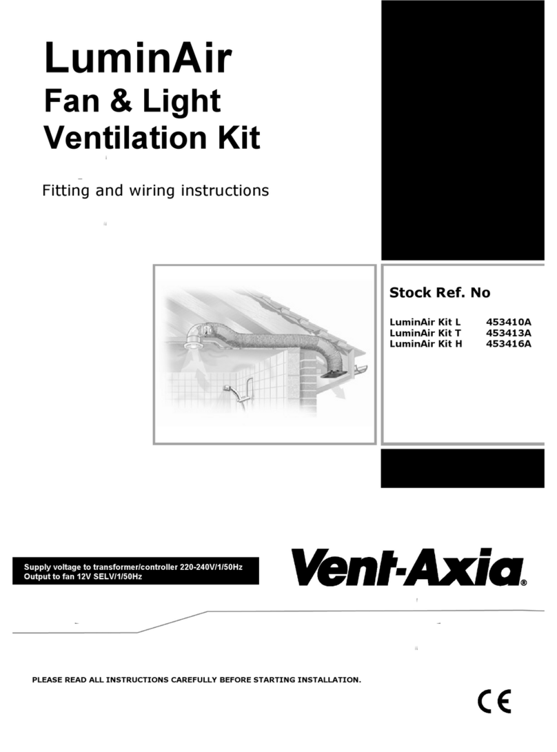
The LuminAir Turbo kit is designed where a more powerful system is required. The kit comprises of a LuminAir
Turbo L or T mains fan, SELV light assembly and transformer, a white bezel, 90 deg bend, 6 metres of flexible
duct, quick fix wall grille and 4 duct ties. The kit extracts moisture and humidity at source, preventing damaging
condensation from spreading.
Siting the LuminAir Vent light
The electrical supply to the LuminAir Vent Light is 12V DC SELV from the mains LED driver. This allows the
LuminAir Vent Light to be installed within reach of a person using a fixed bath or shower ie. In the ceiling above.
However, direct water spray on to the LuminAir Vent Light should be avoided as this will reduce the life of the unit.
Sitting the Transformer
THE TRANSFORMER MUST NOT BE SITED IN A SHOWER CUBICLE OR WITHIN REACH OF A PERSON
USING A FIXED BATH OR SHOWER. (OUTSIDE ZONES 1 & 2 ).
Site away from direct sources of heat. The transformer requires free air circulation and should be mounted
securely to a joist in the roof void. Ambient temperature range of both the LuminAir Vent Light and transformer is 0
to 40°C.
Decide where to mount the LuminAir Vent Light and its transformer and work out the cable runs.
Fitting the LuminAir Vent Light
Mark and cut a 110mm hole in the ceiling where the Vent Light is to be fitted. (Mounting holes on 130mm centres).
Pull the Vent Light bezel from the main assembly by gripping it firmly around its centre. Do not prise the bezel from
the unit as this may damage its clip fastenings.
Loosen the two screws on the lamp housing until the securing clamps allow sufficient clearance to accommodate
the ceiling thickness. Position the securing clamps against the lamp housing and fit the LuminAir Vent Light
through the hole. Retighten the screws to clamp the Vent Light in place. As an alternative the unit may be held in
place with plugs and fixing screws, using the fixing holes provided.
Line up the 3 Clips on the 90°bend and clip it to the Vent-Light assembly.
Connect up the inlet of the turbo fan to the end of the 90° bend using the flexible ducting and duct ties. Always
ensure that the duct is fully extended for maximum performance and that unnecessary duct is cut off.
Fit the bezel back onto the lamp housing.
Fitting the Turbo Fan
Position the fan at the highest point on the system with both ducting runs sloping downwards from this point. In
circumstances where an excessive amount of moisture is present in the air then a condensation trap should be
installed.
Short duct runs terminating close to the fan (i.e within 1.5m) must incorporate suitable guards, unless the fan is
mounted higher than 2.3m. The airflow direction is indicated on the rating label with an arrow pointing in the
direction of the airflow.
Plan the installation carefully, taking into consideration the important points noted, before securely mounting the fan
using the appropriate screws.
To gain access to the mounting holes, proceed as follows: -
A. Using a cross-headed screwdriver, release the two blue plastic clips by undoing the two bolts as shown in
Fig 1. Slide out motor impeller assembly, see Fig 2.
B. The fan can now be mounted at any angle, using the holes provided Fig 3,4,5,6.
C. Once the base is securely fixed, slide the motor impeller assembly back, as shown in Fig 7. Replace the
screw and tighten to lock the assembly together Fig 8.
