Technical User´s Guide 5
DA 50-920
2Mounting Guide
2.1 Introduction to the Mounting
Check that all ordered parts are present and intact according to the delivery note before you start your
work.
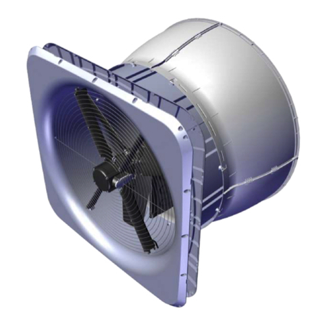
This chapter concerns the general mounting of the DA 50-920 unit, regardless of the type
of building in which it is to be mounted.
As an appendix at the end of the document, you find supplementary mounting guides,
which define the specific mounting conditions depending on the type of building
concerned.
2.1.1 The Appendixes are divided as follows:
Appendix 1, Mounting Guide, Garret
Appendix 2, Mounting Guide, free hanging Roof
Appendix 3, Mounting Guide, free hanging Ridge
Appendix 4, Mounting Guide, Roof through Garret
Appendix 5, Mounting Guide, Ridge through Garret
Appendix 6, Mounting Guide, Monoblock House
Appendix 7, Mounting Guide, flat Roof
2.2 Placement in the House
Place the DA 50-920 units in the house according to the enclosed drawing; however, the placement
depends on purlins, rafters etc. Contact SKOV A/S if there are considerable deviations.
Place the DA 50-920 units evenly distributed with the same spacing in the whole house. The two units
at each end of the house may be placed proportionally farther from the gable to reduce down draught
along the gable.
Check that all DA 50-920 units can be placed freely in relation to other equipment, which may be
mounted later, such as feed lift, water etc., however, as agreed with the building owner.
NB: Note the diameter of the plates for the DA 50-920 units when lifting them past the feed lift, water
etc.
With using Ø920 ducts, it may be an advantage to increase the distance between purlins/rafters where
the DA 50-920 unit is to be placed, and possibly use a stronger purlin/rafter on each side of the unit,
however, as agreed with the building owner. In case of a renovation, however, this is not possible, and
the unit must be placed in the best possible way.
NB: Without affecting the output, the duct can be pressed to a square of c 750 × 750 mm where it
passes purlins/rafters. Use a duct of 1500 mm for this purpose. The duct must be placed so that it is the
middle of the duct, which is placed by the purlins/rafters. Hereafter the duct can be reshaped to
circular form and mounted with the other parts for the unit.
The pull rod must be placed left of the DA 50-920 when you look towards the winch
motor. This also means that you must make sure that the large wire lock of the DA 50-920
funnel tube is to the left.


