2
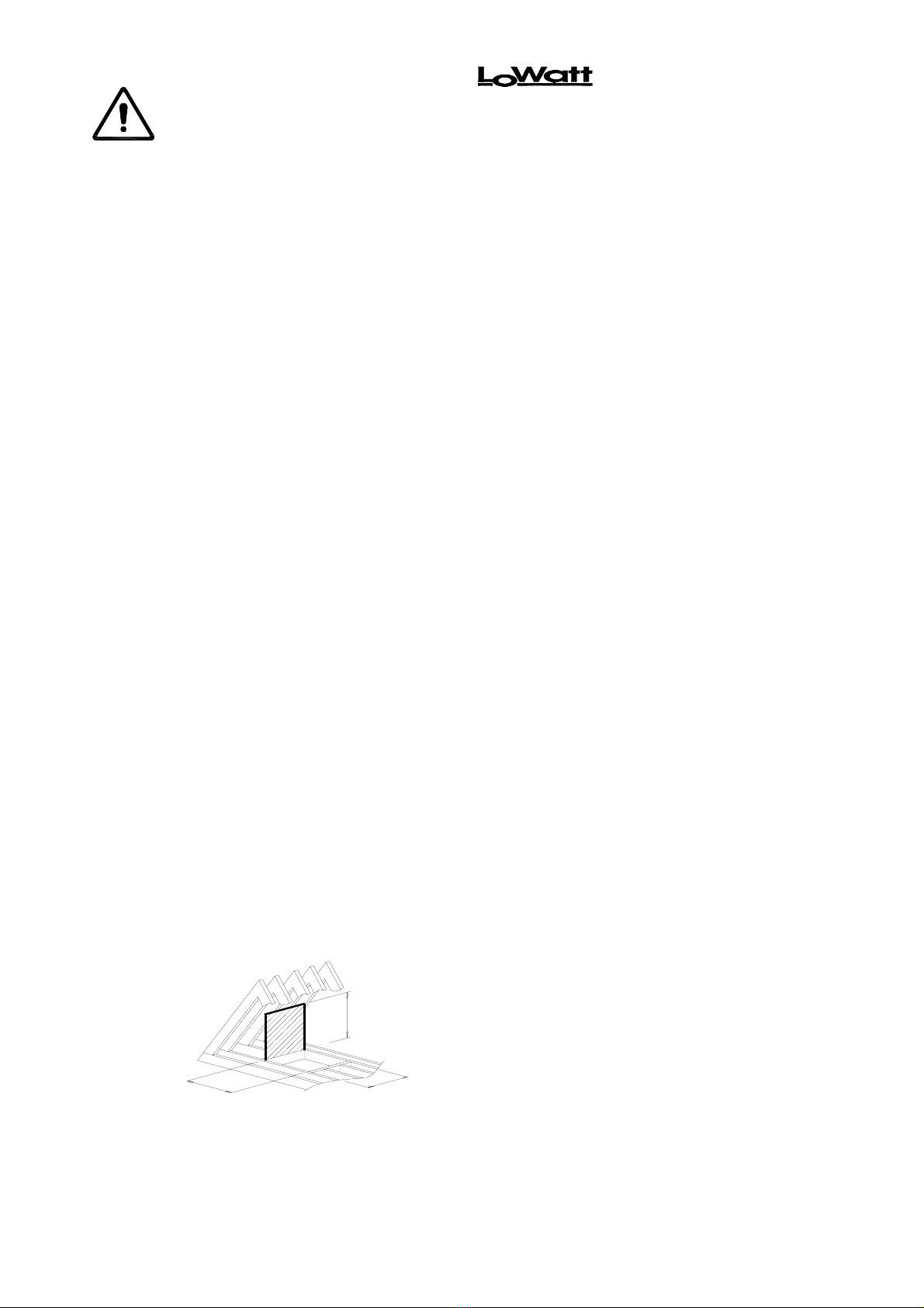
450mm 450mm
1500mm
Minimum
Clearance
Installation and Wiring Instructions for Air Minder Plus Heat Recovery Unit (HRU).
IMPORTANT:
READ THESE INSTRUCTIONS BEFORE COMMENCING THE INSTALLATION
DO NOT install this product in areas where the following may be present or occur:
•Excessive oil or a grease laden atmosphere.
• Corrosive or flammable gases, liquids or vapours.
• Ambient temperatures higher than 50°C or less than –10°C.
• Relative humidity above 90%
• Possible obstructions which would hinder the access to or removal of the Unit.
SAFETY AND GUIDANCE NOTES
•All wiring must be in accordance with building Regulations and the current I.E.E. Wiring
Regulations (BS7671), or the appropriate standards of your country. The installation should be,
inspected and tested by a suitably qualified person after completion.
•The Unit should be provided with a local double pole isolator switch having a contact separation of
at least 3mm.
•Ensure that the mains supply (Voltage, Frequency and Phase) complies with the rating label.
•It is recommended that the connection to the unit is made with flexible cable.
•This Unit should not be used where it is liable to be subject to direct water spray from hoses etc.
•This HRU’s condensate drain must be connected to the building foul water drainage system.
•If an extract grille associated with the HRU is sited in a room containing a fuel burning appliance,
the installer must ensure that air replacement is adequate for both appliances.
•Ensure that the HRU’s external grilles are a minimum of 2m apart and located at least 600mm
away from any flue outlet.
•If the ductwork passes through an unheated loft void or similar location, it should be insulated.
•Certain applications may require the installation of sound attenuation to achieve the sound levels
required.
•The unit must not be connected directly to a Cooker Hood or Tumble Dryer.
•The Condensate Waste pipe must be insulated if it passes through an unheated loft void.
•The Supply and Exhaust Valves must be fully opened prior to commissioning.
•The Supply air must be drawn from the exterior of the property.
•The internal Drain Tray condensate outlet should be clear of debris prior to commissioning.
•The Supply and Exhaust Valves must be positioned a minimum of 300mm from a wall to enable
the airflow measuring equipment to fit correctly over the Valve.
•The unit should be allowed to stabilise during commissioning for a minimum period of 5 minutes
when changing between the Low, Medium and Boost speeds.
•When the unit is fitted in a new build property the Supply and Extract Filter should be checked at
one month intervals for the first six months.
•When the unit is used in conjunction with open flue appliances (see Frost Protection, section I
pg 11) an electrical duct heater must be placed in the Supply (cold fresh air duct, colour green).
PRE-INSTALLATION.
1. Measure the access to ensure that the HRU will pass through the access into the loft space (See below).
The Unit can be installed fully assembled or where the hatch space is limited it is designed so that it can
pass through a 450mm square hole and be assembled in the loft void.
2. The following factors must be considered prior to the installation of the HRU:
¾The Unit’s Condensate drain should be connected to the building foul water drainage system.
¾The Unit must be positioned to allow for the access and removal of the Unit‘s Filters and Heat
Recovery Cube for maintenance purposes.
¾Avoid sudden ductwork bends or transformations close to the Unit.
¾Use flexible connections between the rigid ductwork and the unit spigots.


