Vent-Axia 405215 Advance S User manual

Copyright © 2017 Vent-Axia. All rights reserved.
Advance
MVHR
Installation and User Guide
PLEASE REFER TO ACCOMPANYING DOCCUMENTATION
FOR INFORMATION SPECIFIC TO YOUR UNIT.
PLEASE RETAIN THESE INSTRUCTIONS WITH THE
PRODUCT.
476930B
PLEASE READ THESE INSTRUCTIONS CAREFULLY
BEFORE COMMENCING INSTALLATION OR OPERATION.
Stock Ref. N°
405215 Advance S
473881 Advance S Ventwise
405216 Advance SX
407808 Advance Sp LH
407809 Advance Sp RH
474020 Advance SXp LH
474025 Advance SXp RH

Warnings and Safety Information
2 MVHR Installation and User Guide 476930
Do not install this product in areas where the following may be present or occur:
Excessive oil or a grease laden
atmosphere.
Corrosive or flammable gases, liquids or
vapours.
Subject to direct water spray from hoses.
Ambient temperatures higher than 40°C
and lower than -20°C.
Possible obstructions that may hinder
access to or removal of the unit.
All wiring must be in accordance with the current IEE wiring regulations BS7671, or appropriate
standards of your country. Installation should be inspected and tested by a suitably qualified
person after completion.
Ensure the mains supply (voltage, frequency and phase) complies with the rating label.
The unit should be provided with a local double pole fused spur fitted with a 3A fuse having a
contact separation of at least 3mm. If a unit fitted with a preheater is being installed, a 13A fuse
should be used.
These units must be earthed.
Precautions must be taken to avoid the back-flow of gases into the building from the open flue of
gas or other fuel-burning appliances.
This appliance is not intended for use by persons (including children) with reduced physical,
sensory or mental capabilities, or lack of experience and knowledge, unless they have been given
supervision or instruction concerning use of the appliance by a person responsible for their safety.
Young children should be supervised to ensure that they do not play with the appliance.
The installer is responsible for the installation and electrical connection of the sentinel system on
site. It is the responsibility of the installer to ensure that the equipment is safely and securely
installed and left only when mechanically and electrically safe.
All regulations and requirements must be strictly followed to prevent hazards to life and property,
both during and after installation, and during any subsequent servicing and maintenance.
The unit’s condensate drain must be connected to the building’s wastewater drainage system.
Certain applications may require the installation of sound attenuation to achieve the sound levels
required.
The unit must not be connected directly to a tumble drier.
The supply and exhaust valves must be fully opened prior to commissioning.
The intake air must be drawn from the exterior of the property.
The unit should be allowed to stabilise during commissioning for a minimum period of 5 minutes
when changing between boost and normal speeds.
Ensure that the unit’s external grilles are a minimum of 1500mm apart. The exhaust grille should
be located at least 600mm away from any flue outlet. The inlet grille should be located 2000mm
away from any flue outlet.
This product and associated duct installation should be carried out in accordance with the
Domestic Ventilation Compliance Guide.
UK Building Regulations (Part F) Declaration of Conformance
The unit conforms to the 2010 Building Regulation (Part F - Means of Ventilation, F1(1), F(2)) requirements for fixed
systems for mechanical extract fans when installed in accordance with the instructions in this document and the
Domestic Ventilation Compliance Guide

Contents
MVHR Installation and User Guide 476930 3
Operation and Monitoring 4
Product Description......................................................................4
Accessories................................................................................42
Controlling the unit.......................................................................5
Touch screen display...................................................................5
Control via WiFi............................................................................5
User controls................................................................................6
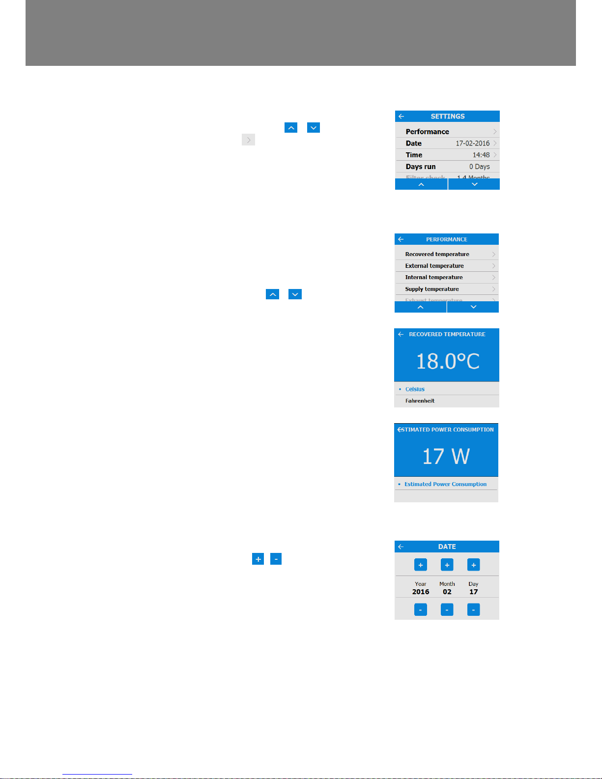
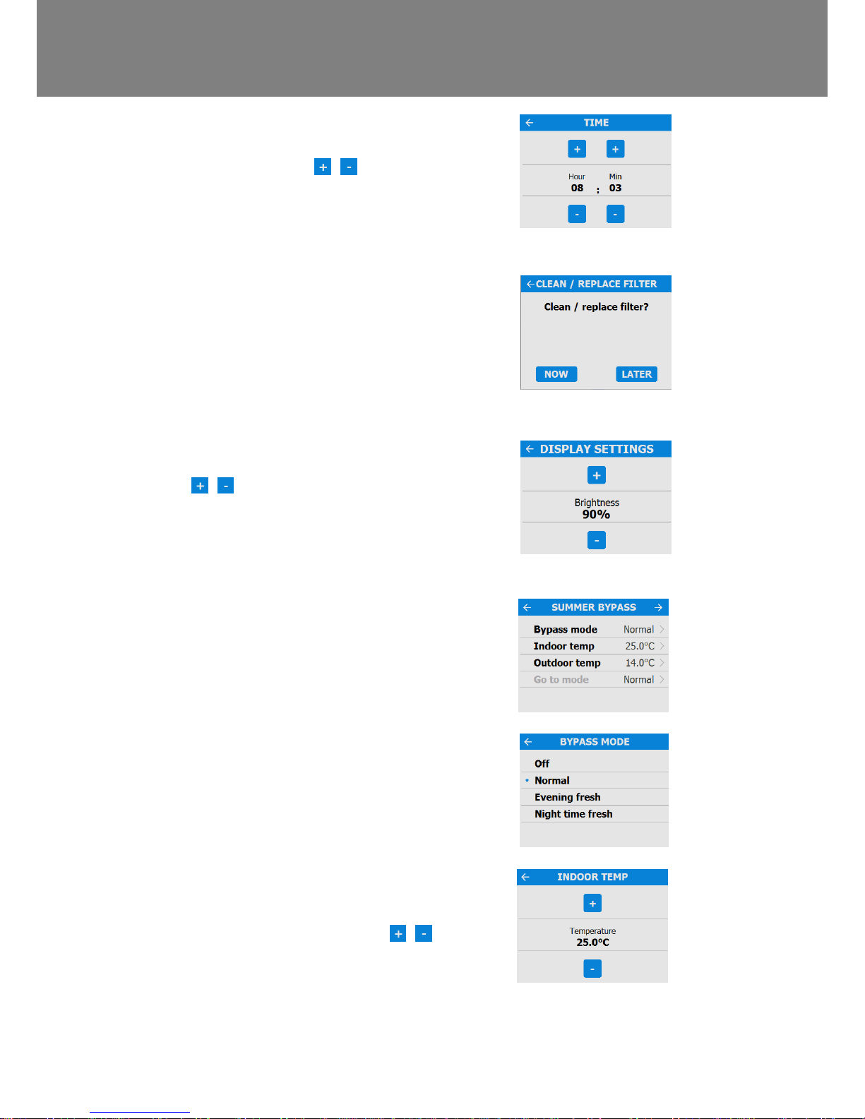
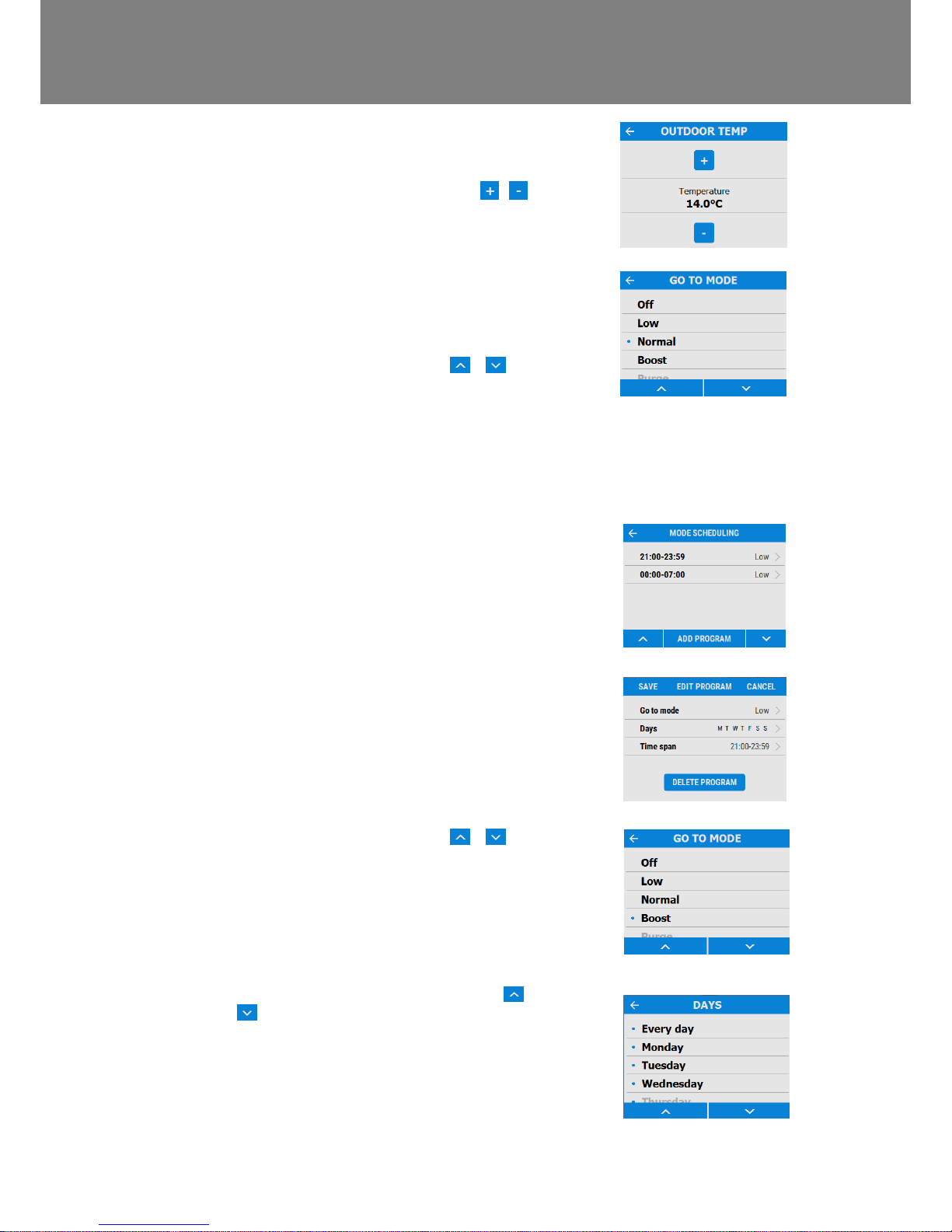
Settings and Performance............................................................7
Control Unit Screens Summary..................................................12
Control Unit Screens Summary..................................................13
Maintenance 14
Filter Maintenance......................................................................14
Periodic Maintenance.................................................................15
Spares .......................................................................................16
Troubleshooting 17
Diagnosing a Problem................................................................17
Installation 18
Overview....................................................................................18
Wall Mounting the Unit...............................................................19
Floor Mounting the Unit..............................................................20
Floor Mounting the Unit (Alternate Method)................................21
Vertical Discharge Condensate Installation ................................22
Attach the Ducting......................................................................23
Electrical Installation ..................................................................24
Connect Switches and Sensors..................................................25
Connect the Power Supply.........................................................27
Commissioning 28
Powering up the Unit..................................................................28
Overview....................................................................................28
Control Unit Touch Screen Display.............................................28
Modifying Settings......................................................................29
Commissioning Screens Summary.............................................30
Modifying Commissioning Settings.............................................32
Commissioning the Unit via USB................................................41
Accessories 42
WiFi Controller...........................................................................42
Ventwise Accessory...................................................................46
Input Switch Accessory..............................................................50
Switched Live Expansion PCB Accessory..................................52
Analogue Input PCB Accessory .................................................54
Wired Remote docking Kit Accessory.........................................56
Technical data 58
Flow Rate settings......................................................................58
Frost Protection..........................................................................58
Summer Bypass Mode...............................................................59
Product Dimensions...................................................................60
Spares .......................................................................................61
Default settings..........................................................................62
Disposal.....................................................................................64

Operation and Monitoring
4 MVHR Installation and User Guide 476930
Operation and Monitoring
Product Description
Mechanical Ventilation/Heat Recovery (MVHR). This heat recovery unit is designed for the energy
efficient ventilation of houses and similar dwellings, conforming to the latest requirements of the Building
Regulations document F 2010.
The unit is designed for continuous 24 hour extract ventilation of stale moist air from bathrooms, toilets,
utility rooms and kitchens. As the stale air is extracted, a heat exchanger within the unit transfers up to
93% of the extract air’s heat, into the supply air entering the bedrooms and lounge. This provides
significant energy recovery, reducing household heat costs, and providing the optimum comfort conditions.
In addition, some models will have features that maintain a constant airflow independent of the blocked
filters.
Figure 1: MVHR with Left Hand and Right Hand spigot configuration.
Units with a preheater are preconfigured from the factory and the handing cannot be changed.
Left Hand
Right hand
Spigot
Filter drawers
Control panel
To
atmosphere
dwelling
Extract from
dwelling
From
atmosphere
Supply to
dwelling
Supply to
dwelling
Extract from
dwelling From
atmosphere
To
atmosphere
Fit condensate
drain with trap this
side. See page 22.
See page 22
Fit condensate drain
with trap this side.
See page 22
Fit drain cap
Fit drain cap

Operation and Monitoring
MVHR Installation and User Guide 476930 5
Controlling the unit
The unit can be controlled via the Touch screen display, via WiFi, switched inputs, or via a third party building
control system.
Touch screen display
The touch screen display can be located on the front of the unit or connected to the unit via a remote docking kit.
The Control Unit provides the user interface for commissioning and monitoring purposes. The display is a resistive
touchscreen with LED backlight, which will turn off to automatically after 5 minutes to minimise power consumption.
To activate the backlight, touch the display.
Navigate through the functions by pressing the symbols, adjust settings using the
buttons. A symbol indicates that there are further screens related to a menu option. Select the
option on the touchscreen to access the related screens.
Control via WiFi
The MVHR WiFi controller is a plug & play accessory that fits next to the control module. It allows the user instant
access to commissioning, configuration, direct monitoring and control of the MVHR unit, using a smart phone or
tablet with the app, available from the iTunes Store or on Google Play.
See page 43 for App address.
User mode (Boost) button
Status bar
Settings & Performance bar
Scroll Left
Scroll Right

Operation and Monitoring
6 MVHR Installation and User Guide 476930
User controls
User Menu Home Screen
The user menu home screen, consists of a User
Mode (BOOST) button, a Machine status bar, and
a Settings / Performance bar.
The Machine status scrolls through Mode of
operation, Summer bypass status and Frost
protection status.
Press Settings / Performance to access these
menus.
User Mode
Scroll through the pre-defined user modes (factory
defaults are BOOST, LOW, and PURGE) using
the buttons either side of the User Mode
button. Select the required function by pressing the
centre button.
When a user mode is selected, select the duration
by pressing the required button from the four
options on the screen.
The button will appear white and the user mode
will flash. A countdown clock will also appear
showing the time remaining for the selected User
Mode.
Pressing the User mode button again will cancel
the User Mode and the unit will default back to
Normal mode.

Operation and Monitoring
MVHR Installation and User Guide 476930 7
Settings and Performance
Settings
Scroll through the settings using the &
buttons and select using where applicable to
access Language, Date, Time, Reset filter, Display
settings, Summer Bypass, Mode Scheduling,
Service phone, Commissioner Menu & Diagnostics.
Days Run and Filter check are reported values and
do not have editable parameters in this section.
Performance
The performance menu shows key performance
indicators such as recovered Temperature and
Estimated power consumption.
Scroll through the list using the & buttons
and select the required parameter.
Each performance temperature can be shown in
Celsius or Fahrenheit by pressing the required
temperature.
Date
Change the date using the / buttons on the
screen.

Operation and Monitoring
8 MVHR Installation and User Guide 476930
Time
Change the time using the / buttons on the
screen.
Note: The clock is 24 hour
Clean/Replace Filter
After maintenance or replacement of the filters, the
filter timer can be reset by pressing NOW.
Press LATER to return to the Settings Menu.
Display Settings
Change the brightness of the touch screen using
the / buttons.
Summer Bypass
See page 9 for a full description of the Summer
Bypass modes and functions
Select the required bypass mode.
The indoor temperature setting is the maximum
desired room temperature. This should be set to 3°
above the central heating temperature.
Change the indoor temperature using the /
buttons on the screen.

Operation and Monitoring
MVHR Installation and User Guide 476930 9
The outdoor temperature is the minimum air
temperature that the bypass will permit. This is to
prevent cold draughts.
Change the indoor temperature using the /
buttons on the screen.
This is the mode the bypass will switch to when
activated.
The suggested Mode for Evening fresh and Night
time fresh setting is Boost.
Scroll through the settings using the &
buttons and select the Go To mode.
Note: Number of available modes may differ from
image shown depending on bypass setting and the
modes set in the commissioning process.
Mode Scheduling
Use a schedule to set a Mode (Airflow setting) for a
fixed, repeated period. For example, set Boost
Mode every morning between 7:00am and 8:00am
while cooking breakfast.
Select the Schedule to view the settings
Scroll through the settings using the &
buttons and select the Go To mode for each
Schedule.
Scroll through the days of the week using the &
buttons and select each day to be included in
the Schedule program.

Operation and Monitoring
10 MVHR Installation and User Guide 476930
Adjust the start and finish times for each day using
the / buttons.
Silent Hours
Silent Hours mode is useful to impose a speed/flow
restriction on the unit to minimise unwanted noise
during the night.
If Silent hours are enabled, the unit will not speed
up above the set Maximum Mode. Silent Hours can
be set to reoccur on specific days and times.
Service Phone
The service phone number can be entered by the
installer and should be used if the unit displays a
fault code, or to arrange routine servicing for the
unit.
Commissioning Menu
Enter the lock code using the / buttons to
access the Commissioner Menu.
Note: the lock code is set by the installer and
settings beyond this point should only be accessed
and modified by a qualified installer.

Operation and Monitoring
MVHR Installation and User Guide 476930 11
Diagnostics
Scroll through the Diagnostics list using the &
buttons to access the following information.
Machine Status, Days Run, Filter Check, Bypass,
Energy Consumption, Air flows, Option boards.
Input status, Output Status, WiFi Status, WiFi
signal.
Note: Optional upgrades may be necessary to view
all information.

Operation and Monitoring
12 MVHR Installation and User Guide 476930
Control Unit Screens Summary
The following Control Unit screens are available for daily operation and monitoring of the unit. Colour and visual
appearance may be different to the below depending on model version and region.
Refer to next page for an
expanded version of
available screens in this
section.

Operation and Monitoring
MVHR Installation and User Guide 476930 13
Control Unit Screens Summary
The following Control Unit screens are available in the Settings / Performance section. Colour, visual appearance, and
some features may be different to the below depending on model version and region.

Maintenance
14 MVHR Installation and User Guide 476930
Maintenance
Filter Maintenance
Heat recovery units require regular maintenance.
This unit has been designed to facilitate access to enable maintenance to be carried out easily.
When the unit displays “Clean or replace
filters”. This is a reminder to ensure that
the filters are not so dirty that they are
blocking the airflow or allowing dirt to pass
through. The rate at which the filters
become dirty will vary hugely depending
on the environment and the activity within
the property.
See page 47 for a list of spare filters.
1. Open the filter drawers by pressing the
finger plate upwards and sliding the drawer
out.
2. Lift each filter out and clean gently by
tapping or carefully using a vacuum
cleaner if necessary.
3. Replace the filters
4. Close the filter drawers, ensuring the
latches have clicked back into the locked
position.
5. After maintenance of the filters, the filter
timer can be reset by going to
Settings/Performance,
Clean/Replace filter.

Maintenance
MVHR Installation and User Guide 476930 15
Periodic Maintenance
WARNING
THE FAN AND ANCILLARY CONTROL EQUIPMENT MUST BE ISOLATED FROM THE POWER SUPPLY
DURING MAINTENANCE.
Fan Filters
Check fan filters as described on the
previous page.
Heat Exchanger Cell
Step 1: Remove the outer cover by
pressing the tabs either side of the control
module and lifting the cover outwards from
the bottom edge.
Step 2: Remove the inner door by undoing
the 4 retaining screws.
Step 3: Slide the heat exchanger out from
the unit.
Step 4: Wash the outer cover and heat
exchanger in warm water using a mild
detergent (such as Milton Fluid) and dry
thoroughly.
NOTE: Keep water away from all
electrical components and wiring within
the unit.
Motors
Inspect the motors for build-up of dust and
dirt on the impeller blades, which could
cause imbalance and increased noise
levels. Vacuum or clean if necessary.
Condensate Drain
Check the condensate drain tube is secure
and clear of debris. Clean if necessary.
Ensure the trap is fully charged with water.
Fastenings
Check that all unit and wall-mount
fastenings are sufficiently tight and have
not become loose. Re-tighten if necessary.

Maintenance
16 MVHR Installation and User Guide 476930
Spares
The following spare parts may be ordered from Vent-Axia:
Part No
Description
472663
Main Power Board
472665
Control Module
472667
Filters G3, 2 per pack
472669
Filters M5, 1 per pack
472671
Filters F7, 1 per pack
472673
Motor Scroll Assembly
472675
Summer Bypass Motor Assembly
472685
Temperature/Humidity Sensor T1 (Right)
472679
Temperature Sensor T2 (Left)
472687
Temperature/Humidity Sensor T3 (Left)
472683
Temperature Sensor T4 (Right)
474529
Constant Volume + Clean Filter Pressure Sensors PCBA
Table 3: Spare parts

Troubleshooting
MVHR Installation and User Guide 476930 17
Troubleshooting
Diagnosing a Problem
In the event of a problem, always troubleshoot the unit according to:
Warning code displayed on the control unit.
A warning code is advisory and will not immediately stop the function of the unit.
Fault code displayed on the Control Unit.
Fault LED if connected.
If no indications are displayed, then troubleshoot problem according to the fault symptom as described in
the following tables.
Service/Fault Code Screens
The Fault Code notification is displayed, when a
fault has occurred. Take note of the fault code
when reporting a fault.
For assistance contact the service provider and quote the fault code number and the product serial
number which can be found behind the front cover.
Note that the fault code is not displayed until the fault has been present for 3 minutes.
The following fault codes numbers may be displayed.
Code numbers are added together if more than one fault is detected.
For example: Code 03 indicates that both left and right fans are not running.
Code
Problem
01
Left Fan Fault
02
Right fan Fault
04
Left Thermistor Fault
08
Right Thermistor Fault
16
Left Centre Thermistor Fault
32
Right Centre Thermistor Fault
64
Left Centre Temp/Humidity Sensor Fault
128
Right Centre Temp/Humidity Sensor Fault
Table 4: Fault Codes

Installation
18 MVHR Installation and User Guide 476930
Installation
Overview
Before installation of the unit
We advise installers to fix all mains and sensor wiring along with any internal accessories prior to fixing
the MVHR unit in position, leaving approximately 500mm tails to allow for internal routing.
Inspect the Unit
When taking delivery of the unit, check the items delivered against the enclosed delivery note. Inspect the unit for
damage in transit. If in doubt, contact Customer Services. Each box contains a heat recovery unit, a wall bracket
and accessory pack containing miscellaneous fixings and product documentation.
Unit Installation
Installation should be carried out by a suitably qualified and competent person.
If the unit is wall mounted, the wall should have sufficient strength to support the unit
The unit may also be floor mounted, either directly to the floor or using standard kitchen cabinet feet (not supplied).
Ensure that the unit is mounted upright.
If a constant volume unit is being installed a straight run of ducting of at least 0.7m in line with the unit must be
used.
Do not use this unit as a support for any other equipment.
Service Void
Clearance must be left around the unit to allow for cleaning and servicing, the dimensions below are the minimum
requirements. The condensate drain trap used will dictate the necessary clearance below the unit which may be
larger than the minimums.
Select Unit Configuration
The unit is configurable as either Left or Right Handed (Default), see page 5 for the spigot configuration. Use the
left hand condensate drain for the Left Hand configuration, the right hand drain for the Right Hand configuration. If
the unit is fitted with a preheater, the configuration is factory set and cannot be altered.

Installation
MVHR Installation and User Guide 476930 19
Wall Mounting the Unit
Step 1: Mark the wall bracket position
using the dimensions shown. Note the
position of the top of the unit in relation
to the wall bracket. Ensure the bracket
position is horizontal.
Step 2: Attach the wall bracket to the
wall using appropriate fixings.
Step 3: Lift the unit and locate the two
hooks on the rear onto the wall bracket.
Step 4: Use the two adjusters at the
bottom of the unit to ensure the base of
the unit is horizontal in both axis. Lock
the adjusters in the correct position
using the two M6 nuts.

Installation
20 MVHR Installation and User Guide 476930
Floor Mounting the Unit
Step 1: The unit has 44 x 12mm deep
fixing holes on the underside suitable
for a No.6 screw. Pre drill a board using
the dimensions shown, and cut 2 x
105mm minimum diameter holes for the
condensate drain access.
Step 2: Mount the board to the
underside of the unit using appropriate
fixings.
Note: Ensure any other cabling
requirements (e.g. sensor, control
cables etc) are routed through the two
cable channels as required prior to
attaching the board.
The board may then be attached to
joists, flooring, or equivalent.
Vent-Axia recommend that where
possible, the wall bracket is used in
conjunction with any floor mount
solution to prevent the unit from tipping.
Step 3: Mark the wall bracket position
using the dimensions shown. Note the
position of the top of the unit in relation
to the wall bracket. Ensure the bracket
position is parallel to the floor.
Step 4: Attach the wall bracket to the
wall or batten using appropriate fixings.
(As shown on page 12)
Step 5: Lift the unit and locate the two
hooks on the rear onto the wall bracket
prior to fixing the unit to the floor. (As
shown on page 12)
7
Other manuals for 405215 Advance S
1
This manual suits for next models
6
Table of contents
Other Vent-Axia Ventilation manuals