Vent-Axia Air Minder Plus User manual

AIR MINDER PLUS
LET YOUR HOME BREATHE
INDOOR AIR QUALITY/HEAT RECOVERY WHOLEHOUSE
VENTILATION SYSTEMS FROM
USER GUIDE
IMPORTANT: TO BE LEFT WITH END USER

CONTENTS
Introduction .................................................................................................. Pg 1
Wholehouse Heat Recovery unit ............................................................... Pg 2
1: Screen Displays ....................................................................................... Pg 3
2: Boost Speed Override (Manual) ............................................................ Pg 4
3: SettIng The Controller Clock ..................................................................... Pg 5
4: Adjusting Medium Speed Running Time ............................................... Pg 6 - 7
5: Adjusting The Summer Bypass Indoor Comfort Level .......................... Pg 8 - 9
(This facility is only available on certain models)
Routine Inspection and Maintenance ....................................................... Pg 9
AIR MINDER PLUS
LET YOUR HOME BREATHE

11
Thank you for choosing Vent-Axia Air Minder Plus!
Dear User.
Thank you for choosing the Vent–Axia Air Minder Plus Wholehouse Ventilation System with Heat Recovery. The system
is designed to improve the air quality of your home, whilst reducing the effects of condensation.
The system provides continuous ventilation to the whole property. Extracting stale moist air from the kitchen and
bathrooms, whilst simultaneously supplying fresh tempered air to your bedrooms and living rooms. As the stale air is
extracted, the heat exchanger within the unit retains 90% of the heat and transfers it to the supply air, thus
giving continuous air circulation with minimal heat loss.
Your Air Minder Plus comes complete with a digital controller that continuously shows you the status of the unit,
displaying the time and the speed, e.g. medium day time speed or low night time speed.
If your installation requires different settings, refer to section 4 for set up procedures.
Boost speed: On the right hand side of the controller is a boost button, this can be used to change the unit
to high speed when extra ventilation is required. The unit will revert back to its normal speed
at the next time change interval, or alternatively you can change it back by depressing the
button again.
Defrost Mode: If the external air drops below -1°C, to reduce the risk of frost forming on the heat exchanger
the defrost mode is activated, this allows the supply fan to stop until the external
temperature rises, the extract fan continues to run to allow the internal air to pass a small
amount of heat over the exchanger. In installations where a negative pressure is not
permitted, your installer will have to set the Air Minder Plus to leave the incoming fan on during
defrost mode and open the bypass instead.
Heating Failure: If for any reason the heating system in your house fails and the internal
temperature drops below 5°C the unit will stop running so as to not bring cold air into an
already cold house. Your unit will start up every 60 mins and will run for a short time
to measure the temperature of the property. Once the temperature rises eg: the heating
system is switched back on the unit will restart and continue its normal operation.
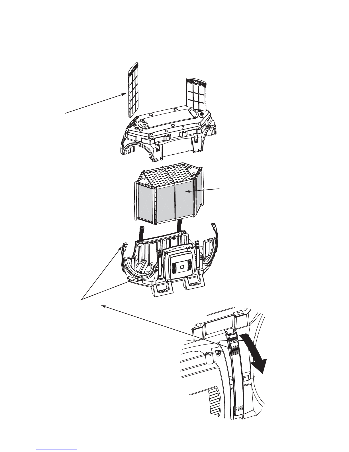
Filter Check Once every 3 months your controller will display the words ‘check filter’, when this occurs
the filters should be checked and if necessary cleaned or replaced. After the filter has been
checked the timer on the controller needs to be reset, this can be achieved by pressing and
holding down the ‘ ’ and ’V’ keys for 10 seconds.
For AM290FB and AM375FB models only.
Summer Bypass: The Bypass damper activates when the outside air temperature is equal to or below
the pre-set ‘Comfort Temperature’ (adjustable between 16° and 30°C). The unit’s internal
damper opens allowing the cooler fresh air from the outside to bypass the Heat Recovery
Cube and reduce the internal temperature to the required pre-set ‘Comfort Temperature’.
When the inside air temperature reaches the pre-set ‘Comfort Temperature’ the Bypass
Damper closes.
V
AIR MINDER PLUS
LET YOUR HOME BREATHE

22
AIR MINDER plus
WHOLEHOUSE HEAT RECOVERY UNIT
Air Filters
Unscrew the screws on the side
of the Heat Recovery Cube and
remove the Cube.
Six yellow Locking Straps
Release the Locking Straps and lift the Top Housing
away from the Base Housing to gain access to the
Heat Recovery Cube.

33
AIR MINDER plus
1: SCREEN DISPLAYS
SET
>
>
1
p
u
Tu
Med i
1
mS
:15
eed
e
>
>
SET
EDRFOSTTAC VIE
E
O
MDSSPABY
>
>
SET
EDRFOSTTAC VIE
>
>
E
A
H
F
NIAT
NO
SET
IAFGR
U
LE
FF
EL URGFAITAINHE
-
>
>
FA RNE
SET
RTSA ITGN
1:1 Normal Running Mode (Daytime Running shown).
Typical Displays:
Daytime: Medium Speed: On 06:00 / Off 22:30
Night Time: Low Speed: On 22:30 / Off 06:00
1:2 Defrost Mode
When the external intake air temperature is between
0ºC and -5ºC the defrost mode will automatically
activate. This mode will reduce the supply airflow
rate and increase the extract airflow rate to prevent
frost forming on the heat exchanger.
When the external intake air temperature is below -
5ºC the defrost mode will automatically activate. This
mode will automatically switch off the supply fan, the
extract fan will continue to run at a reduced rate to
prevent frost forming on the heat exchanger.
1:3 Defrost Bypass Mode (AM290FB & AM375FB models only)
The intake air temperature has fallen to -1°C
or below.
A Damper within the Heat Recovery Unit has
opened to bypass the heat recovery cube, when
the intake air temperature rises above 0°C the
damper will close and normal running mode
will resume.
1:4 Heating Failure (Protective) Mode FLASHING
(Activates in the event of central heating failure).
When the heating system in the dwelling fails to
maintain an internal temperature of 5°C. (e.g. Boiler
failure), the Heat Recovery Unit will automatically
switch off and ‘Heating Failure’ will be displayed on
the controller.
1:5 Central Heating Failure
(Fan Re-Starting) Mode FLASHING
The Heat Recovery Unit will continue to attempt to
re-start by checking the internal temperature for a 10
minute period every 60 minutes. When the Extract
temperature rises above 5°C the unit will revert back
to normal running mode.

1:6 Filter Check
(Alternates every 3 seconds with 1:1 display).
Filter inspection required of the Intake and Extract Filters.
The Heat Recovery Unit’s filters will require regular
inspection and cleaning. (Refer to the Heat
Recovery Unit’s fitting and wiring instructions).
To reset the automatic reminder, press and hold
down the ‘ ’ and ‘V’ keys for 10 seconds.
1:7 System Failure
If a fault is found then the Air Minder Plus is turned
off and the service telephone number shown;
alternating with the Fault code number.
Fault code number
1= Intake Fan not running
2= Exhaust Fan not running
3= Neither Fan running
Add
8 = Temperature Sensor T1 faulty
16 = Temperature Sensor T2 faulty
For example, a fault code of 10 indicates both
Exhaust Fan and Temperature Sensor T1 at fault.
For assistance contact your installer or service
provider and quote the Fault code number.
1:8 System Running Time
To display the Total Running Time (Hours).
Press and hold the ‘ ’,’V’ and ‘SET’ Keys for 5 seconds.
The display will return to normal running display
after 10 seconds.
Note:
The timer cannot be re-set. In the event of power
failure total time will be retained.
2:1. Press the ‘Boost Key’ to override the current speed
setting (Low or Medium depending on the Time Cycle).
The display will change from the default setting to
the screen below:
2:2. Press the ‘Boost Key’ again and the controller will
return the current speed setting (Low or Medium
depending on the Time Cycle).
Note:
If the ‘Boost Key’ is not pressed to return the speed
to the current setting, the speed will return to
default speed at the next change of the time cycle.
44
AIR MINDER plus
SET
>
>
F
Chckilt
eer
SET
>
>
2
ee
S
3
vri P
2
0
ch
0
n
oe
1456789
SET
>
>
ug
Rnni T
H
ni
e
m
HHHH
u
>
>
eu
T
de
Mi
SET
1 11 :5
ee
p
Sd
m
Boos tSpeed
5
111
eu
T:
Boost key
V
V
1
p
u
Tu
Med i
1
mS
:15
eed
e
Default Setting
2: BOOST SPEED OVERRIDE (MANUAL)

55
AIR MINDER plus
3: SETTING THE CONTROLLER CLOCK
3:1 When the controller is initially connected to the
unit, the following display will appear:
3:2 Setting the Day
Press the ‘ ’ or ‘V’ Key to select the day.
Press the ‘Set’ Key, and the day is set and the
hour will start to flash.
3:3 Setting the Hour
Press the ‘ ’ or ‘V’ Key to select the hour.
Press the ‘Set’ Key, and the hour is set and the
minutes will start to flash.
3:4 Setting the Minutes
Press the ‘ ’ or ‘V’ Key to select the minutes.
Press the ‘Set’ Key, and the minutes are set and the
display will scroll to the next setting screen.
Note:
If you keep the ‘ ’ or ‘V’ Key depressed for more
than 2 seconds, the display will enter fast scroll mode.
>
SET
>
S
T
C
t
e
ue
k
oc
l
0:00
>
SET
>
S
T
C
t
e
ue
k
oc
l
1:00
1
>
SET
>
S
T
C
t
e
ue
k
oc
l
1:15
1
V
V
V
V
>
SET
>
S
S
C
t
e
un
k
oc
l
0:00

66
AIR MINDER plus
4: ADJUSTING MEDIUM SPEED RUNNING TIME
4:1. Press the ‘ ’ Key twice and the display will change
from the default setting to the screen below:
4:2. Selecting the Day to be adjusted.
Press the ‘SET’ Key and the day will start to flash.
Press the ‘ ’ or ‘V’ Key to select the day required,
press the SET’ Key again, the day will be set, and the
on hour will start to flash.
4:3. Setting the On Hour
Press the ‘ ’ or ‘V’ Key to select the on hour, press the
‘SET’ Key again and the on hour will remain on and
the on minutes will start to flash.
4:4. Setting the On Minutes
Press the ‘ ’ or ‘V’ Key, to select the on minutes,
press the ‘SET’ Key again and the on minutes will
remain on and the off hour will start to flash.
4:5. Setting the Off Hour
Press the ‘ ’ or ‘V’ Key to select the off hour,
press the ‘SET’ Key again and the off hour will
remain on and the off minutes will start to flash.
>
>
SET
irF
Med
6:
0
O
:
0
022
nO
00
ff
>
>
SET
irF
Med
7:
0
O
:
0
022
nO
00
ff
u
>
>
eu
T
de
Mi
SET
1 11 :5
ee
p
Sd
m
>
>
SET
irF
Med
7:
0
O
:
5
122
nO
00
ff
>
>
SET
irF
Med
7:
0
O
:
5
123
nO
00
ff
euT
Med
6:
0
O
:
0
022
nO
30
ff
DAY HOUR MINUTES HOUR MINUTES
V
V
V
V
V
Default Setting

4:6. Setting the Off Minutes
Press the ‘ ’ or ‘V’ Key, to select the off minutes,
press the ‘SET’ Key again and the off minutes will
remain on.
The on/off time settings are now complete
4:7. Selecting additional Days to be adjusted.
Press the ‘SET’ Key for the next day.
Follow steps 4:3 to 4:6 to alter the Medium Speed
Running time required for that day.
Follow steps 4:3 to 4:7 for any additional days.
If no additional alterations are required, continue to
press the ‘SET’ Key, until the normal running display
appears (Medium or Low Speed will be displayed,
depending on the time).
Note:
When the system is running in non default mode
(the Medium Running times have been altered),
an additional symbol ( ) is displayed in the bottom
right hand corner of the display.
Press the Boost Button for 12 seconds to reset to
daytime and night time default settings.
77
AIR MINDER plus
i
d
>
rF
Me
>
SET
O
7:
023
5
1
nO
4: 5
ff
>
>
SET
taS
Med
6:
0
O
:
0
022
nO
30
ff
SET
>
>
1
p
u
Tu
Med i
1
mS
:15
eed
e
Tue
Mde
:
e
11
u
imS
p
15n
ed
V

88
AIR MINDER plus
5:1. Press the ‘ ’ Key until the display changes to the
screen below:
(Indoor Default temperature is set at 20°C).
5:2. Selecting the Indoor Comfort Temperature.
Press the ‘SET’ Key and the temperature will start
to flash. Press the ‘ ’ or ‘V’ Key and select the
temperature required. The Indoor temperature is
adjustable from 16°C to 30°C.
5:3. Setting the Temperature.
Press the ‘SET’ Key, the temperature will remain on
and the display will change.
5:4. Return to Normal Running
The display will return to normal running after a short
period of time, if no keys are pressed.
5:5. Summer Bypass Active
When the Summer Bypass is active, the top line of
the display screen will alternate (for 10-second)
between ‘Summer Bypass On’ or ‘Med / Low Speed’
(depending on day time or night time running).
>
>
SET
e
0
Pe
lS
2
m
e
C
p
ase tT
>
>
SET
e
In
dTp
2
m
3C
oor
>
SET
>
M
T
m
u
i
de
ue
p
S
11
dee
1
:5
>
SET
>
S
T
REMM
U
ue
YB
11
SAP
1
:5
SON
5: ADJUSTING THE SUMMER BYPASS INDOOR COMFORT LEVEL
((TTHHIISSFFAACCIILLIITTYYIISSOONNLLYYAAVVAAIILLAABBLLEEOONNCCEERRTTAAIINNMMOODDEELLSS..))
TEMPERATURE
C02
IndooTme
rp
V
V
u
>
>
eu
T
de
Mi
SET
1 11 :5
ee
p
Sd
m
Default Setting

AIR MINDER plus
ROUTINE INSPECTION AND MAINTENANCE
WARNING:
THE FAN AND ANCILLARY CONTROL EQUIPMENT MUST BE ISOLATED FROM THE POWER
SUPPLY PRIOR TO, AND DURING MAINTENANCE.
SET
>
>
F
Chckilt
eer
Air Filters
‘Check Filter’ display
(Alternates every 3 seconds with normal running screen).
An inspection of the Intake and Extract Filters are required on
average every three months. An automatic timed reminder is flashed
on the HRU’s Controller.
When the unit is fitted to a new build property the Intake and Supply
filters should be checked at one month intervals for the first six months.
1. Withdraw the filters as shown on page 2. (Place in a large plastic bag and move to a safe working area).
2. Using a vacuum cleaner remove any loose dust particles from the filter.
3. If further cleaning of the media is required, release the catches in the outer frame, remove the filter media and
wash in warm soapy water.
4. Replace the filter media in the filter frame and allow it to dry.
5. Insert the filters back into the HRU.
6. To reset the automatic reminder on the Controller, press and hold the ‘ ’ and ‘V’ Keys for 10 seconds.
Heat Recovery Cube
At intervals appropriate to the installation (e.g.Yearly), the Cube should be inspected and cleaned to ensure there
is no build up of airborne contaminates.
1. Remove the Filters and Cube as shown on page 2.
(Place in a large plastic bag and move to a safe working area)
2. Using a vacuum cleaner, remove any loose dust particles from the outside of the Cube.
3. Using a low pressure water hose, wash out the airways to remove any dust particles and allow to dry.
4. Replace the Cube and Filters (If applicable) as shown on page 2.
V
5:6. Winter Setting
To prevent the Summer By Pass facility activating
during the Winter.
Press the ‘V’ ‘ ’ and ‘Set’ keys for more than 5 seconds
until the display changes to the screen opposite.
Press the ‘ ’ until the display changes to the screen
opposite.
Press the ‘Set’ key until the display changes to the
screen opposite.
Note the screen will return to its normal display after 20
seconds.
>
SET
>
R
0
ninn
u
00
Tg
02
emi
>
SET
>
S
O
remm
u
n
oMed
>
SET
>
S
O
remm
u
f
oMed
f
99
V
V

AIR MINDER PLUS
LET YOUR HOME BREATHE
Vent-Axia Limited
Fleming Way
Crawley
West Sussex
RH10 9YX
Tel: +44 (0) 1293 441535
Fax: +44 (0) 1293 539209
INTERNET SITE AT: www.vent-axia.com
EMAIL: info@vent-axia.com
CONTACTS
1818/0308
402006G
As part of the policy of continuous product improvement Vent-Axia reserves
the right to alter specifications without notice.
Other manuals for Air Minder Plus
1
Table of contents
Other Vent-Axia Ventilation manuals