Veranda 2127099 User manual

IMPORTANT, RETAIN FOR FUTURE REFERENCE:
READ CAREFULLY
7PC COUNTER HEIGHT FIRE DINING SET
ITM. / ART. 2127099
m# FG-VGO7FHDS
Customer Service
E-Mail : customerservice@foremostgroups.com
8:30a.m.– 5:00p.m. EST, M-F
Toll Free 1-855-390-5474 (English/Spanish)
(Int.) 001-855-286-4931 (English/Spanish)
Fax: (973) 428-8026
Website: www.foremostgroups.com
906 Murray Road East Hanover, New Jersey 07936 US
11

WARNING!
THIS ITEM IS INTENDED FOR OUTDOOR DOMESTIC USE ONLY, NOT FOR COMMERCIAL USE.
Please read instructions carefully and thoroughly before assembling. Check parts against
the parts list to make sure you have all the parts needed for proper assembly. Familiarize yourself
with the inventory of parts and the accompanying illustrations to ensure safe and proper assembly.
PARTS LIST
Failure to tighten bolts may cause injury. Do not force components and over tighten the nuts during assembly.
Place chair on a non-abrasive flat surface to prevent scratching. Hang wet cushion over chair frame to dry to prevent mold / mildew.
To ensure longevity of your patio set, each seat cushion is made with high density foam. With initial use the seat cushions may
feel firm, but with continued use the cushions will continue to soften and provide the ultimate comfort for seasons to come.
ABurner cover BTable Top CBurner Pan
D E Right Side Panel F Back Panel
G Door H Gas Tank Support IGas Tank Baffle
J K Foot glider LDoor handle
Left Side Panel
Fire Glass
1 PC 1 PC 1 PC
1 PC 1 PC 1 PC
1 PC 1 PC
4 PCS
1 PC
1 PC2 BOXES (TOTAL 26.4 lbs)
2

4 PCS 4 PCS
1 PC 1 PC
4 PCS
4 PCS 10 PCS 10 PCS
20 PCS 20 PCS 1 PC
AA Bolt (5/16” x 30mm) BB Flat Washer (φ8.5) CC Lock Washer (φ8.5)
DD EE Bolt (1/4” x 25mm) FF Bolt (1/4” x 30mm)
GG Flat Washer (φ6.5) HH Lock Washer (φ6.5) II Wrench
JJ KK Natural gas orifice
Nut (5/16”)
Allen Wrench
PARTS LIST
6 PCS 6 PCS
24 PCS
24 PCS
48 PCS 24 PCS
6 PCS
2 PCS
M Chair Bucket N Base O Bolt (5/16” x 35mm)
P Q R
S
Flat Washer (φ8.5)
T
Lock Washer (φ8.5)
Seat CushionWrench
Nut (5/16”)
3

INSTALLER: Leave this manual with the appliance.
CONSUMER: Retain this manual for future reference WARNING: For Outdoor Use Only.
DANGER
FIRE OR EXPLOSION HAZARD
WARNING
Do not store or use gasoline, or other
flammable vapors and liquids,in the
vicinity of this or any other appli-
ance.
An LP-cylinder not connected for use
shall not be stored in the vicinity of
this or any other appliance.
Installation and service must be per-
formed by a qualified installer, service
agency, or the gas supplier.
DANGER
CARBON MONOXIDE HAZARD
This appliance can produce carbon monoxide which has no odor.
Using it in an enclosed space can kill you.
Never use this appliance in an enclosed space such as a camper,
tent, car or home.
WARNING:
If the information in this manual is not followed exactly, a fire or explosion may result causing
property damage, personal injury, or loss of life.
If you smell gas:
Shut off gas to the appliance.
Extinguish any open flame.
If odor continues, leave the area immediately.
After leaving the area, call your gas supplier or fire
department.
Failure to follow these instructions could result in
fire or explosion, which could cause property
damage, personal injury, or death.
MODEL#: TMHFT19
ANS Z21.97 CSA 2.41-2017
Outdoor Decorative Gas Appliances
4

IMPORTANT SAFETY INFORMATION
The installation must conform with local codes or, in the absence of local codes, with the National Fuel Gas
Code, ANSI Z223.1●NFPA 54; National Fuel Gas Code; Natural Gas and Propane Installation Code, CSA B149.1;
or Propane Storage and Handling Code, CSA B149.2, as applicable.
The appliance must be isolated from the gas supply piping system by closing its individual manual shutoff valve
during any pressure testing of the gas supply piping system at test pressures equal to or less than 1/2 psi (3.5
kPa).
The maximum inlet gas supply pressure is 250 psi.
The appliance area must be kept clear and free from combustible materials, gasoline, and other flammable vapors
and liquids.
Do not use this appliance if any part has been under water. Immediately call a qualified service technician to
inspect the appliance and to replace any part of the control system and any gas control that has been under water.
Children and adults should be alerted to the hazards of high surface temperatures and should stay away
to avoid burns or clothing ignition.
Young children should be carefully supervised when they are in the area of the appliance.
Clothing or other flammable materials should not be hung from the appliance or placed on or near the
appliance.
Any guard or other protective device removed for servicing the appliance shall be replaced prior to oper-
ating the appliance.
Installation and repair should be done by a qualified service person. The appliance should be inspected
before use and at least annually by a qualified service person. More frequent cleaning may be required as
necessary. It is imperative that the control compartment, burners, and circulating air passageways of the
appliance are kept clean.
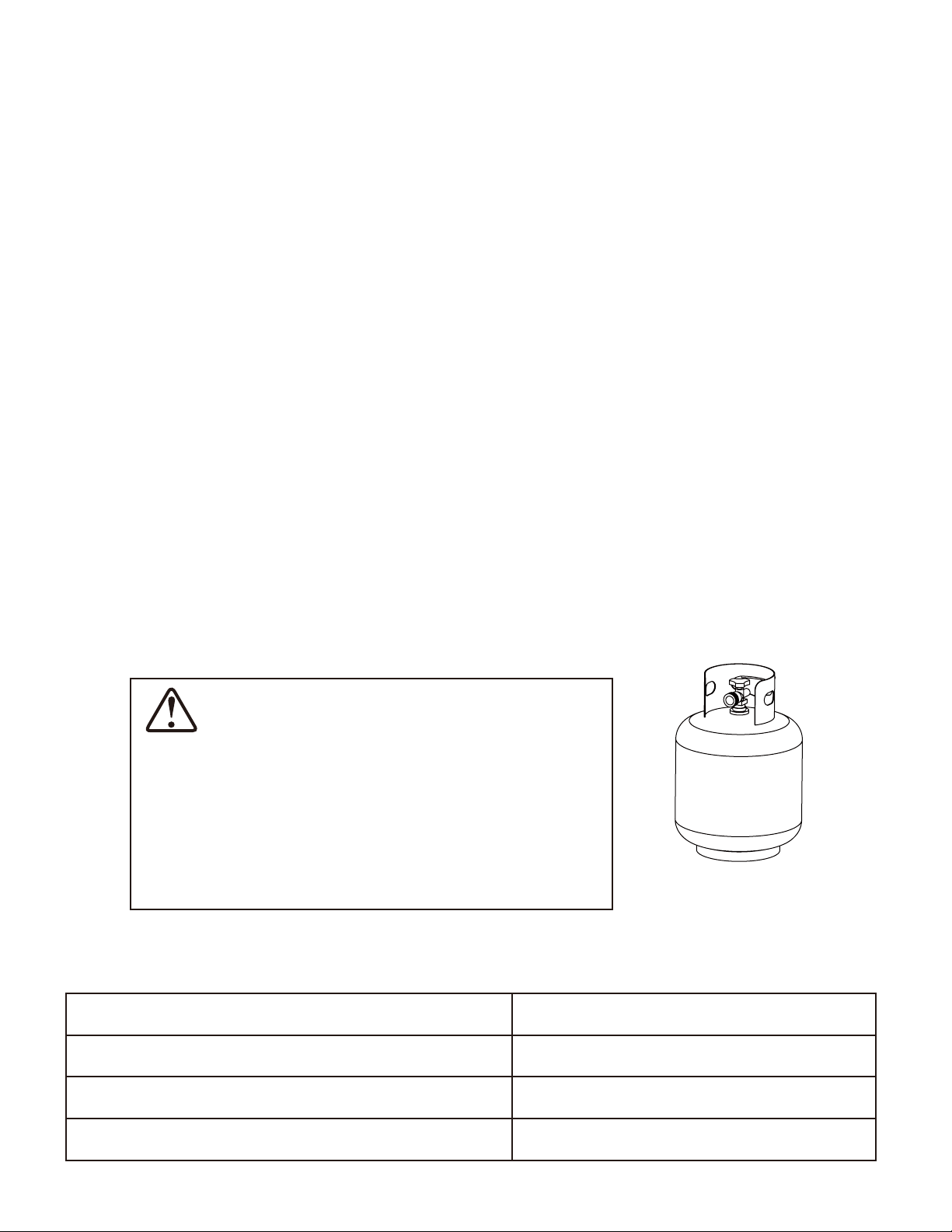
CAUTION: The propane gas pressure regulator provided with this appliance must be used. This regulator is set
for an outlet pressure of 11 inches water column.
DO NOT burn solid fuels in this appliance.
This outdoor gas appliance is for Outdoor Use ONLY.
This outdoor gas appliance is not intended to be installed in or on recreational vehicles and/or boats.
This outdoor appliance is not for use on wood decks or other flammable surface.
Before each use of this gas appliance, open the door and/or the LP (Liquid Propane) Tank Drawer and inspect the
hose. If there is evidence of excessive abrasion or wear or if the hose is damaged, the hose assembly must be
replaced prior to the appliance being put into operation. Use only the replacement hose assembly specified in this
manual. Make sure to leak test.
Before each use of this gas appliance, inspect the burner. The burner must be replaced prior to the appliance
being put into operation if it is evident that the burner is damaged. Use only the replacement burner specified in
this manual.
Make sure to properly locate the gas hose including locating the hose out of pathways where people may trip over
it or in areas where the hose may be subject to accidental damage.
Keep the fuel supply hose away from any heated surface.
Never use this appliance closer than 10 feet from anything flammable, including houses or overhead tree branch-
es.
Never use gasoline, kerosene, or any other liquid fuel to start a fire.
Always maintain a safe distance from the fire.
Always supervise children around the fire.
Never leave a fire unattended.
The appliance is hot during and after use, always allow ample cooling time before touching or moving.
1.
2.
3.
4.
5.
6.
7.
8.
9.
10.
11.
12.
13.
14.
15.
16.
17.
18.
19.
20.
21.
22.
23.
24.
25.
5

IMPORTANT SAFETY INFORMATION ABOUT
PROPANE (LP) GAS
1. The LP-gas supply cylinder to be used must be constructed and marked in accordance with the U.S.
Deparment of Transportation (D.O.T.) Specifications for LP-Gas Cylinders, or the Standard for Cylinders,
Spheres and Tubes for Transportation of Dangerous Goods and Commission, CAN/CSA-B339, as applicable.
2. The LP-gas supply cylinder to be used must have a listed overfilling prevention device (See Figure 1).
3. The LP-gas supply cylinder to be used must have a cylinder connection device compatible with the connection
for the appliance.
4. A self-contained LP-gas cylinder for use with this appliance must have a capacity of 20 Ibs cylinder (Height
approximately 18 in., Tank Body approximately 12 in. diameter, Base approximately 8 in. diameter).
5. The cylinder supply system must be arranged for vapor withdrawl.
6. The cylinder used must include a collar to protect the cylinder valve.
7. This appliance shall be used only outdoors in a well-ventilated space and shall not be used in a building,
garage or any other enclosed space.
8. When this appliance is not in use, the gas must be turned off at the supply cylinder.
9. Storage of this appliance indoors is permissible only if the cylinder is disconnected and removed from the
appliance.
10. Cylinders must be stored outdoors in a well-ventilated area out of the reach of children. Disconnected
cylinders must have threaded valve plugs tightly installed and must not be stored in a building, garage or
anyother enclosed areas.
11. This appliance is certified by CSA (Canadian Standards Association) to ANS Z21.97 CSA 2.41-2017,
Outdoor Decorative Gas Appliances.
SPECIFICATIONS
Rated Heat Input (Liquid Propane & Natural Gas)
Propane Regulator Pressure
Natural Gas Inlet Pressure
Clearance to combustible surfaces
50,000 BTU/hr
11 inches water column
7 inches water column
Sides: 24in. (610mm), Top: 72in. (1829mm)
Fuels used in liquefied propane gas appliances, and
the products of combustion of such fuels, can expose
you to chemicals including benzene, which is known
to the State of California to cause cancer and cause
birth defects or other reproductive harm. For more
information go to: www.P65Warnings.ca.gov.
WARNING
Standard 20 Ib.tank
Figure 1
6

ASSEMBLY INSTRUCTIONS
NOTE: Tool Required for Assembly: phillips screw driver ( NOT included)
Hardware Used:
EE Bolt (1/4” x 25mm) 4
GG Flat Washer (φ6.5) x
x
4
HH LockWasher (φ6.5) x 4
Figure 2
Remove all protective material carefully. Avoid cutting the surface of the furniture while removing the packaging material
on all components.
Loosely attach Back Panel (F) to the Left Side Panel (D) and the Right Side Panel (E) by bolts (EE) through lock
washers (HH), flat washers (GG), using Allen wrench (JJ). See figure 2.
DO NOT TIGHTEN BOLTS AT THIS POINTS.
JJ Allen Wrench x 1
1.
EE JJ
HH
GG
Loosely attach Burner Pan (C) to the Left Side Panel (D) and Right Side Panel (E) by bolts (FF) through lock washers
(HH), flat washers (GG), using Allen wrench (JJ).
4. Loosely attach control panel from Burner Pan (C) to the Right Side Panel (E) by bolts (EE) through lock washers (HH),
flat washers (GG), using Allen wrench (JJ). See figure 3.
DO NOT TIGHTEN BOLTS AT THIS POINTS.
3.
HH
GG
C
GG
Control
Panel
D
EE
E
FF
HH
D
E
F
Figure 3
Hardware Used:
EE Bolt (1/4” x 25mm) x 4
GG Flat Washer (φ6.5)
x 8
HH Lock Washer (φ6.5)x 8
JJ Allen Wrench x 1
FF Bolt (1/4” x 30mm) x 4
2.
7
JJ

Hardware Used:
FF Bolt (1/4” x 30mm)
GG Flat Washer (φ6.5) x
x
4
4
HH Lock Washer (φ6.5)x 4
Loosely attach Gas Tank Support (H) to the Left Side Panel (D) and Right Side Panel (E) by bolts (FF) through lock
washers (HH), flat washers (GG), using Allen wrench (JJ). See figure 4.
DO NOT TIGHTEN BOLTS AT THIS POINTS.
JJ Allen Wrench x 1
5.
Loosely attach Gas Tank Support (H) to the Gas Tank Baffle (I) by bolts (FF) through lock washers (HH), flat washers
(GG), using Allen wrench (JJ). See figure 5.
DO NOT TIGHTEN BOLTS AT THIS POINTS.
6.
Figure 5
GG
D
FF
JJ
E
HH
H
FF
HH
I
G
JJ
G
H
Figure 4
8
Hardware Used:
FF Bolt (1/4” x 30mm)
GG Flat Washer (φ6.5) x
x
2
2
HH Lock Washer (φ6.5)x 2
JJ Allen Wrench x 1

Figure 6
Loosely attach Door (G) to the Right Side Panel (E) by bolts (EE) through lock washers (HH), flat washers (GG), using
Allen wrench (JJ). See figure 6.
Once all the bolts are in place. Securely tighten all the bolts (EE&FF) with Allen wrench (JJ). Base fully assembled.
7.
Hardware Used:
AA Bolt (5/16” x 30mm)
BB Flat Washer (φ8.5) x 4
CC Lock Washer (φ8.5) x 4
Figure 7
Fix the Table Top (B) onto the Base Assembly with Bolt (AA), Flat Washer (BB), Lock Washer (CC) and Nut (DD), screw
the Nut (DD) tightly by using the Wrench (II). See figure 7.
DD Nut (5/16”) x 4
II Wrench
x 1
9 .
EE
JJ
HH
G
GG
E
BB
CC
B
DD
II
AA
D
E
8.
9
Hardware Used:
EE Bolt (1/4” x 25mm)
GG Flat Washer (φ6.5) x
x
2
2
HH Lock Washer (φ6.5)x 2
JJ Allen Wrench x 1
x 4

Figure 10
Figure 9
11.
12. Place the burner cover (A) onto the fire bowl when not in use to protect it from the elements or when fire pit is
cooled COMPLETELY after use (see Figure 10).
NOTE: Allow 30 minutes after use for fire pit to cool down before placing the lid to prevent scalding.
Open the door, place the gas cylinder into gas cylinder support (F), connect the regulator, screw the black
handle clockwise to tighten, turn the black handle counterclockwise to remove. Secure the gas cylinder by
tightening clockwise the retention point found on gas cylinder support (F), so that the gas cylinder cannot move
from side to side or fall down. The knob on the control panel is turned all the way to the “OFF” position when
the fire pit is NOT in use (see Figure 9).
10. Place glass beads or lava rock (J) around the burner, leave the pilot box uncovered (see Figure 8).
A gas fire pit requires 26.4 lbs glass beads.
NOTE: DO NOT completely cover the burner element or block the pilot box with the glass beads.
When the first use, preheat the glass beads for 15 minutes to burn out the impurities and air in
the natural or glass beads.
WARNING: keep children away during assembly, as this item contains glass beads, which are small
pieces and can be swallowed by children.
Figure 8
pilot box
B
J
C
retention point
F
F
black handle
10

Figure 11
Figure 12
Figure 13
STOP STOP
NATURAL GAS CONVERSION
Natural gas conversion must be performed only by natural gas provider or service company.
1. Disconnect the propane hose from the gas valve (see Figure 11).
2. Unscrew and disconnect the propane orifice from the bellows (see Figure 12). Propane orifice
(2.21 mm diameter size) is painted with red mark.
3. Replace the propane orifice with the natural gas orifice, screw the natural gas orifice with the bellows
tightly,then connect and tighten the natural gas orifice with inlet tube (see Figure 13). Natural gas orifice
(4.18 mm diameter size) is painted with black mark.
propane orifice
bellows
propane orifice
bellows
inlet tube
bellows
natural gas orifice
propane hose
gas valve
CAUTION: The gas supply shall be shut off prior to disconnecting the electrical power, before
proceeding with the conversion.
11

Figure 16
5. Stick and cover the conversion label onto the propane rating plate (see Figure 16).
propane rating plate
WARNING: This conversion kit shall be installed by a qualified service agency in accordance with the
manufacturer’s intructions and all applicable codes and requirements of the Authority Having Jurisdiction.
If the information in these instructions is not followed exactly, a fire, explosion or production of carbon
monoxide may result causing property damage, personal injury or loss of life.
The qualified service agency is responsible for the proper installation of this kit. The installation is not proper
and complete until the operation of the converted appliance is checked as specified in the manufacturer’s
instructions supplied with the kit.
conversion label
Figure 14 Figure 15
4. Connect the natural gas hose with the gas valve by screwing clockwise tightly (see Figure 14). Plug the
natural gas fixture into the natrual gas supply piping system (see Figure 15).
gas valve
natural gas hose
natural gas fixture
natural gas supply
piping system
Conversion kit should be CSA certified and purchased from the market, the conversion kit hose
connector and quick disconnect listed as below.
(1). Part# DH22 / QH1, manufacturer: KSUN
or (2). Part# WH02 / KJ50A2, manufacturer: Laite
or (3). Part# KJ-3/8G-3/8 / KJ-3/8G, manufacturer: Wanan
The natural gas orifice is included in the package. Please follow the instructions for gas conversion.
Distributed by Foremost Groups, Inc.
906 Murray Road, East Hanover, NJ 07936, U.S.A.
Model No: TMHFT19
Serial No:
Design Certified by CSA Group
ANS Z21.97-2017 CSA 2.41-2017
Outdoor Decorative Gas Appliances
Minimum Clearance From Unit To Combustible
Construction: 72” (182.9cm) from the top, 24” (61cm) from all sides and back.
For Outdoor Use Only. If Stored Indoors, Detach and LeaveCylinder Outdoors.
The gas supply must be turned off at the LP-gas supply cylinder when this appliance is not in use.
WARNING:
Do not store or use gasoline, or other flammable vapors and liquids, in the
vicinity of this or any other appliance. An LP-cylinder not connected for use
shall not be stored in the vicinity of this or any other appliance.
WARNING:
If the information in this manual is not followed exactly, a fire or explosion may
result causing property damage, personal injury, or loss of life.
WARNING:
Placing the cylinder too close to the appliance might cause the fire hazard or
property loss or even life hazard.
WARNING:
Improper installation, adjustment, alteration, service or maintenance can cause
property damage, personal injury or loss life. Refer to the owner's information
manual provided with this appliance. Installation and service must be performed
by a qulified installer, service agency, or the gas supplier.
Complies with ANS Z21.97-2017 CSA 2.41-2017, Outdoor Decorative Gas Appliance Standards.
Cover must be removed when burner is in operation.
Removal of this marking will void compliance with standard ANS Z21.97-2017 CSA 2.41-2017.
Do not connect to a remote gas supply.
LIGHTING INSTRUCTIONS
1. Push in gas control knob slightly and turn to “OFF”.
2. Turn gas control knob to “ON/MIN”.
3. Push in gas control knob all the way and hold. Continue to press the ignition button for 15 seconds.
4. If the burner does not light in 15 seconds, release the knob and it will pop back out. Wait 5 minutes before attempting to light the burner
again, repeat step 1 to 3.
TO TURN OFF GAS
1. Push in gas control knob slightly and turn to “OFF”.
The instruction manual contains important information necessary for the proper assembly and safe use of the appliance.
Read and follow all warnings and instructions before assembling and using the appliance.
Follow all warnings and instructions when using the appliance.
If instructions or parts are missing, contact Foremost Groups Customer Service Department toll free in the United States at 1-800-443-1410
between the hours of 8:30 AM and 5:00 PM EST, Monday through Friday or via email at [email protected]
CAUTION: This appliance has been converted to use natural gas. Propane orifice dia 2.21 mm,
natural gas orifice dia 4.18 mm.
Rated Heat Input: 50,000BTU/hr (14.65 kW).
Type Gas: Natural gas
Manifold Pressure: 7 inches water column (1.74 kPa).
This appliance was converted on (day-month-year) to
(insert gas type; e.g. Natural or Propane) gas with Kit. No. by
(name and address of organization making this conversion), which accepts the responsibility that this
conversion has been properly made.
12

Figure 17
BATTERY
WARNING:
Make sure the control knob is in the “OFF” position. Unscrew the push button cap on the ignitor module located
on the control panel to access the battery compartment. The ignitor module requires one AAA size battery (see
Figure 12),
BATTERY IS NOT INCLUDED.
1. Please observe proper polarity and use the correct battery type when placing or replacing the battery.
Improper installation could result in ignition failure.
2. Please remove the battery if consumed or if product is to be left unused for a long period of time.
OFF
ON/MIN
Marche/Min
IGNITOR
Dispositif d'allumage
(1.5 V)
AAA BATTERY
COMPARTMENT
INSTALL ( ) SIDE
FIRST
-
Compartiment à
piles AAA (1,5V)
installer l'extrémité
(-) en premier
Arrêt
MAX
Max
3. Unscrew the battery compartment cap on the control panel and install one AAA battery (not included) with
the anode end of the battery located towards the battery compartment cap. (See Fugure 18)
Battery
Compartment
Cap
Battery
Figure 18
13

Make 2~3 oz. of leak solution by mixing one part liquid dishwashing detergent and three parts water.
NOTE: make sure control knob is “OFF”.
Apply several drops of solution where the cylinder attaches to regulator (see Figure 19), inspect the solution at the
connection looking for bubbles. If NO bubbles appear, the connection is secure. If bubbles appear, the connection
has the leak, disconnect the regulator, reconnect, perform another leak check. If you continue to see bubbles after
several attempts, cylinder valve is defective and should be returned to cylinder’s supplier.
Apply several drops of solution where natural gas fixture attaches to natural gas supply piping system connection
(see Figure 20), If NO bubbles appear, the connections are secure. If bubbles appear, the connection has the leak,
disconnect, reconnect, perform another leak check. If you continue to see bubbles after several attempts, the part
is defective and should replace the part.
Apply several drops of solution where gas valve attaches to bellows (see Figure 21), where gas valve attaches to
hose (see Figure 22), and where inlet tube attaches to bellows (see Figure 23). If NO bubbles appear, the connec-
tions are secure. If bubbles appear, the connection has the leak, disconnect, reconnect, perform another leak
check. If you continue to see bubbles after several attempts, the part is defective and should replace the part.
To perform a leak test:
gas valve-hose connection (Figure 22) inlet tube-bellows connection (Figure 23)
1.
2.
3.
4.
LEAK TEST
1. Always perform the leak test as described below before lighting this appliance or each time the
cylinder is connected for use.
2. Do not smoke or allow other sources of ignition in the area while conducting a leak test.
3. Conduct the leak test outdoors in a well-ventilated area.
4. Do not use matches, lighters or a flame to check for leaks.
5. Do not use this appliance until any and all leaks are corrected. If you are unable to stop a leak,
disconnect the propane supply. Call a gas appliance service shop or your local propane gas supplier.
To prevent fire or explosion hazard when testing for a leak:
cylinder-regulator connection (Figure 19)
natural gas fixture-natural gas supply
piping system connection (Figure 20)
gas valve-bellows connection (Figure 21)
14

LIGHTING INSTRUCTIONS
1. Push in gas control knob slightly and turn to “OFF”.
2. Turn gas control knob to “ON/MIN”.
3. Push in gas control knob all the way and hold. ontinue to press the ignition button for 15 seconds.
4. If the burner does not light in 15 seconds, release the knob and it will pop back out. Wait 5 minutes before
attempting to light the burner again, repeat step 1 to 3.
WARNING: For your safety, read and follow the Lighting Instructions in this manual and in the Rating Plate
on the appliance. IMPROPER LIGHTING PROCEDURES COULD RESULT IN A FIRE HAZARD OR
EXPLOSION HAZARD OR PROPERTY DAMAGE, INJURY OR LOSS OF LIFE.
TO TURN OFF GAS
1. Push in gas control knob slightly and turn to “OFF”.
gas control knob
ignition button
Figure 24
OFF
ON/MIN
Marche/Min
IGNITOR
Dispositif d'allumage
(1.5 V)
AAA BATTERY
COMPARTMENT
INSTALL ( ) SIDE
FIRST
-
Compartiment à
piles AAA (1,5V)
installer l'extrémité
(-) en premier
Arrêt
MAX
Max
15

Observe Flame Height When Lit: The burner will display blue and yellow flames. These flames should be
a blue / yellow color between 1~2 in. height (see Figure 25). These flames should not be yellow or produce
thick smoke. This would indicate an obstruction of airflow through the burners. The flames should be blue
with straight yellow tops.
Figure 25
CARE AND MAINTENANCE
Yellow
Yellow
Light Blue
Light Blue
Blue Blue
Good Bad
To enjoy the outstanding performance from your fire pit, make sure you perform the following activities on a
regular basis:
1. Use warm soapy water for cleaning. Never use flammable or corrosive cleaning agents.
2. While cleaning the fire pit, make sure to keep the area around the burner dry at all times. DO NOT
submerge the control valve assembly. If the gas control is submerge in water, DO NOT use it. It must
be replaced.
3. Air flow must be unobstructed. Keep controls, burner, and circulating air passageways clean. Signs of
possible blockage include:
(1). Gas odor with extreme yellow tipping of flame.
(2). Fire pit does NOT reach the desired temperature.
(3). Fire pit flame is excessively uneven.
(4). Fire pit makes popping noises.
(5). Spiders and insects can nest in burner or orifice. This dangerous condition can damage fire pit and
render it unsafe for use. Clean burner holes by using a heavy-duty pipe clearer. Compressed air
may help clear away small particles.
4. Carbon deposits may create a fire hazard. Clean burner with warm soapy water if any carbon deposits
develop.
5. Cover your fire pit with an outdoor weather cover when not in use to protect it from the elements.
NOTE: Always allow fire pit to cool COMPLETELY before you cover the fire pit with an outdoor weather
cover or you attempt the service or maintenance.
16

17
Figure 26
ASSEMBLY INSTRUCTIONS
Remove all protective material carefully. Avoid cutting the surface of the furniture
while removing the packaging material.
Place the chair base (N) on a flat surface. Remove the Bolt (O), flat washers (P), lock washers (Q) and nuts (R)
from the chair bucket (M). Loosely attach the chair bucket (M) to the base (N). Please insert bolts (O) through
flat washer (P) followed by support bar, square TR. Secure with flat washers (P) lock washers (Q) and nuts (R).
Use wrenches (S) provided to securely tighten all nuts (R) and bolts (O). (Figure 26)
M
N
Square TR
Support Bar O
S
S
P
P
Q
R
80% force
S
O
P
P
Q
R
S
100% force

Figure 27
Place the seat cushions (T) on the chairs. (Figure 27)
T
18

MADE IN INDONESIA / FABRIQUÉ EN INDONÉSIA / HECHO EN INDONESIA
CARE & MAINTENANCE
Clean furniture frame with wet towel using mild soap and water solution. Dry completely with soft towel. Clean cushions and sling seat material with a
mild solution of soap and water and hang cushions to drip dry completely. Store them in a clean dry area of your home. Do not machine wash or dry.
Do not use bleach or strong solvents to clean any of your patio furniture. It will harm both fabrics and metal finishes. Caution should be used when using
oils, lotions and other chemicals such as chlorine or repeated exposure to extreme weather conditions (including heat), which may cause permanent
discoloration to the fabric. To maintain and protect the furniture, always cover it with an outdoor furniture cover or store in a safe area when not in use
for long periods of time.
Tips and Info on Cushion Use:
To ensure longevity of your patio set, each seat cushion is made with high density foam. With initial use the seat cushions may feel firm, but with conti-
nued use the cushions will continue to soften and provide the ultimate comfort for seasons to come.
Extended exposure to the elements can contribute to cushions becoming water saturated. To combat this, allow your cushions to air-dry properly with
these quick tips:
1. Unzip the cushion cover to ventilate and facilitate the drying process. Do not remove the cushion covers completely.
2. Place cushions upright, with the zipper facing down to drain excess moisture faster.
For best results, store cushions indoors during inclement weather and rainy seasons.
Sunbrella® Fabric Cleaning Instructions:
Sunbrella® fabric should be cleaned regularly. Brush off any loose dirt and wash with a mild soap and lukewarm water solution. For stubborn stains
and mildew, wash with a solution of 236 ml (1 cup) of bleach and 59 ml (1/4 cup) of mild soap per 3.8 l (gallon) of water. Rinse thoroughly to remove
soap. Allow fabric to air dry.
Distributed by:
Costco Wholesale Corporation
P.O. Box 34535
Seattle, WA 98124-1535
USA
1-800-774-2678
www.costco.com
Costco Wholesale Canada Ltd.*
415 W. Hunt Club Road
Ottawa, Ontario
K2E 1C5, Canada
1-800-463-3783
www.costco.ca
*faisant affaire au Québec sous
le nom les Entrepôts Costco
Importado por:
Importadora Primex S.A. de C.V.
Blvd. Magnocentro No. 4
San Fernando La Herradura
Huixquilucan, Estado de México
C.P. 52765
RFC: IPR-930907-S70
(55)-5246-5500
www.costco.com.mx
Costco Wholesale Australia Pty Ltd
17-21 Parramatta Road
Lidcombe NSW 2141
Australia
www.costco.com.au
Costco Wholesale UK Ltd /
Costco Online UK Ltd
Hartspring Lane
Watford, Herts
WD25 8JS
United Kingdom
01923 213113
www.costco.co.uk
Costco Wholesale Spain S.L.U.
Polígono Empresarial Los Gavilanes
C/ Agustín de Betancourt, 17
28906 Getafe (Madrid) España
NIF: B86509460
900 111 155
www.costco.es
Costco Wholesale Iceland ehf.
Kauptún 3-7, 210 Gardabaer
Iceland
www.costco.is
Costco France
1 avenue de Bréhat
91140 Villebon-sur-Yvette
France
01 80 45 01 10
www.costco.fr
Costco Wholesale Japan Ltd.
3-1-4 Ikegami-Shincho
Kawasaki-ku, Kawasaki-shi,
Kanagawa 210-0832 Japan
0570-200-800
www.costco.co.jp
Costco Wholesale Korea, Ltd.
40, Iljik-ro
Gwangmyeong-si
Gyeonggi-do, 14347, Korea
1899-9900
www.costco.co.kr
Costco Wholesale New Zealand Limited
2 Gunton Drive
Westgate
Auckland 0814
New Zealand
Costco (China) Investment Co., Ltd.
Room 1003, Block 2, 2388 Xiupu Road,
Pudong New Area, Shanghai
China 201315
+86-21-6257-7065
Costco Wholesale Sweden AB
Saluvägen 5
187 66 Täby
Sweden
19
This manual suits for next models
1
Table of contents
Other Veranda Outdoor Furnishing manuals
Popular Outdoor Furnishing manuals by other brands

Acme Furniture
Acme Furniture 02093 Assembly instructions

Frog Furnishings
Frog Furnishings Plaza Assembly instructions

New England Arbors
New England Arbors UPS Regency Assembly guide

Lifetime
Lifetime 60283 Assembly instructions

Arbor Technology
Arbor Technology Fortem Assembly instructions

highwood
highwood Sequoia Professional Exeter CM-BENSQ62 Assembly guide