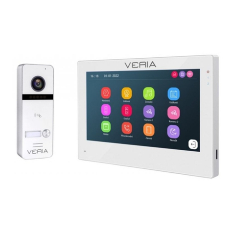
Veria 831 RFID User manual

VERIA
User's guide
Videophone entry station
Model: VERIA 831 RFID
Veria
Please read this manual carefully before use
and keep it in case of further need
1. Description of the establishment

1
Microphone
2
Camera lens
3
Infra diodes of night light
4
Speaker
5
Bell button
6
Console snap holes
7
Connection cable
8
"RESET" button cover
9
Fixation screw thread
10
RFID reader
2. Contents of the package
Component
Number of pieces
Note
Entry station
1
Fixing brackets
1
For attachment to a flat surface
Caret
1
Cover ALU
Dowle
2
Ø6 x 28 mm
Screw
2
Ø3 x 30 mm
Screw
2
Ø3.5 x 30 mm
Cross screw
2
M3 x 8 mm (connection of straight
and angle brackets)
Screwand mbus
1
M3 x 5 mm (connection of straight
console and station)
Imbus key
1
2 mm
User's guide
1
RFID Chip
2
125kHz

3. Technical specification of the equipment
Camera
1/4"CMOS;color;700TVL;110° CVBS 1080P viewing angle
Number of buttons
1
Link
2-wire digital transmission
Video signal/impedance
1 channel digital video
Audio signal/impedance
Digital audio
Lock control
1x (NO, 12V/DC, max.2A)
1x (NC,12V/DC, max.0.35A)
Night light
Yes, 6 x IR diode
Backlighting buttons
Yes
Anti-vandal design
Yes
Cover material
Aluminum
Mounting
Surface with fixing bracket
Power/subscription
24 V DC from monitor <0.3A / 3W
Dimensions (T/H/H)
152 x 55 x 22 mm
Operating conditions
-25°C �+60°C, humidity not condensing 0%~95%
Storage conditions
-30°C �+60°C
4. Access station connection diagram
1.Electric lock
2.Gate drive
3.Outbound lock opening button
4.Sensor
Wire colors:

1 R: RED
2 Y: YELLOW
3W: WHITE
4BK: BLACK
5GN: GREEN
6OG: ORANGE
7BN: BROWN
8BU: BLUE
"RESET" button
If the input station is experiencing non-standard behavior, restart the device, unplug the
application,remove the rubber button reset cover, connect the powersupply, press the reset
button within 1 minute until 2x ton sounds. Put the rubber cover back on and install the
entrance station according to the instructions.
Wiring diagram.
Adapter 24V/ 1A DC

Source for DIN rail 24V DC PW03A
Cable length.
1. Cables maybe unenled.
2.Distance L2 means the distance from the entrance station to the power supply of the
system.
3.Distance L1 means the total distance of the 2-wire bus.
4.The same bus should use the same conductor with the same specification.
1Installation may be carried out by a person who is knowledgeable and properly trained
for VERIA systems.

DC24V/1A
Power
Adapter
Source
PW03A
Cable type
Monitor
length
vst.unit L1m
(MAX)
Power cable
length L2m
(MAX)
Monitor
length
vst.unit L1m
(MAX)
Power cable
length L2m
(MAX)
1
Parallel cable
125
125
125
125
2
Parallel cable
125
125
125
125
3
Twisted cable
150
150
150
150
4
Twisted cable
150
150
150
150
5
Cat-5 Standard
150
100
150
100
6
PAIR CABLE CAT-5
200
150
200
150
7
Telephone cable line
2x0,2mm
50
50
50
50
8
Parallel cable
100
100
100
100

5. Assembly
The installation height of the entrance station is recommended about 140 cm from the floor.
Do not install the station in a place exposed to direct sunlight and weather conditions.
Installation
1) Remove the surfacemounting bracket from the rear of the entrance station and use it as a
template for
marking the location of the openings.
2) Drill the marked holes and insert the enclosed dowels (when installed on a hard surface,
such as
is wood or metal, it isnot necessary to use these dowels).
3) Using screws Ø3 x 30 mm, fix the surface console to the surface with the surface.
4) Place the entrance station on the flat fixing bracket and secure the M3 x 5 mm stationusing
the hex screw at the bottom.

NOTE: For security reasons, do not connect the videophone monitor to the power grid
before installation is complete. When
installation of an entrance station on site with insufficientprotection forthosewiththeleast to
extend the life ofthose devices
we recommend filling the space between the surface and the fixing bracket with silicone
sealant outside the bottom for drainage
Condensate.
Videophone wires should not be routed in the same cable as conductors of other
installations (bell, alarm, telecommunication
systems) and not more than 15 m in parallel with another el. Leadership.
WARNING: Failure to follow this procedure for installing the entry station may result in
permanent damage and
loss of warranty!
6.RFID Access Control Management
Warning:
Access and access chips are set up in the VERIA monitor menu.
In standby mode, attach the registered chip to the entrance station, the door will open after
1 beep. If the entry station reads an unregistered card, there will be a 2x beep to alert you to
the unregistered chip.
Press the settings icon on the main menu to enter the interface settings, then tap DEVICE
CONFIGURATION, and then click DOOR STATION LIST. Press the door station you want to
change, press edit, enter your password, and confirm with the # icon to enter the edit
interface. Press ACCESS CONTROL and make the settings below:
6.1 Access status
It is turned on by default. If users do not want to use the card access control feature,
deactivate this item.
6.2 Register 125kHz access chip or cards
Touch the screens tosee the message below:
Attach the chip to the door panel ...... the button at the entrance station starts flashing. In this state,
the user can register new chips for the input station. When a user inserts a new chip to the reading
area on the door panel, the chip will be registered after 1xpin. The same procedure for

adding additional access chips. After registering all chips, leave the ACCESS CHIP
REGISTRATION interface.
Note: The information about the registered chip is stored in the door station, so you can
manage it on any internal monitor that connects to the door station. If it's a private door
station, it can only be managed with call destination monitors.
6.3 Checking/managing information about a registered chip.
All information about the registered access chip can be found in the LIST OF VALID
REGISTERED CHIPS. Select any registered chip in the list and to enter the submenu, then you
can edit the chip information. To pause a single access card, press MOVE to the invalid card
list. To delete all information about a registered card, press delete the access information.
6.4 Backing up information about a registered chip .
Insert the micro SD card into the vidotelephone monitor. Then go to ACCESS CONTROL
MANAGEMENT, press THE REGISTERED CARD IT backup, a submenu will appear, tap
CONFIRM to start the backup. When the backup ends, it returns to ACCESS CONTROL
MANAGEMENT.
The backup of access card information is stored on the SD card in the AccesData folder.
6.5 Recover registered card information.
Access DATE folder, submenu appears, press to refresh information about registered cards.
Specifications
N.o.
Item
Description
1
Communication
Digital 2 wire
2
Audio
Digital audio (bidirectional)
3
Video
1-channel digital video (output)
4
Camera
1080P HD color CMOS camera
5
Night light
Infrared LEDs (with automatic adjustment )
6
Effective distance (0 Lux)
0.5 m
7
Viewing angle
Horizontal 110 degrees, Vertical 50 degrees
8
Button
1x mechanical
9
Supply voltage
24V/DC 0.3A max.
10
El.lock support
NC Lock of DC12V 0.35A (Max), or NO Lock of
DC12V, ≤2A (instant).
11
Gate drive support
Unlock signal , potential-free contact
12
Chip/card support
CARD ID(125KHz)
13
Card read distance
≤20mm
14
Number of participating chips/cards
1000

15
Consumption
3W
16
Working temperature
-25°C- +60°C
17
Storage temperature
-30°C- +60°C
18
Dimensions
137x49x20mm
Warranty
SAFE HOME europe s.r.o. as a supplier, liable to the original buyer that this product will be
free from any defects in material and design during normal use and operation for a period of
24months from the date of sale. The supplier's obligation under this guarantee is limited to
the replacement of the product. Repair of the product or its replacement with a repaired
product is at the supplier's decision. The full terms and conditions and information regarding
warranty and warranty service can be found on the www.safe-home.eu.
SAFE HOME europe s.r.o. declares that the product complies with the basic requirementsand
other other decentprovisions of theDirective. The devicecan befreely operated in theEU.
Declarationsofconformity can be found onthe webpagesof www.safe-home.eu.

VERIA
is a trademark for the company's products:
SAFE HOME europe, s.r.o. Seat of the company:
Havlíčkova 1113/47, 750 02 Přerov
Czech Republic
Tel.: +420 581 222 262
Website: www.veria.eu
SAFE HOME europe, s.r.o. reserves the right to modify
and change product specifications without notice.
All materials are carefully inspected, but the company
SAFE HOME europe, s.r.o. is not responsible for any
consequences caused by printing errors
or errors in the translations of this manual.
© 2021 SAFE HOME europe, s.r.o.
All rights reserved.
This manual suits for next models
1
Table of contents
Other Veria Intercom System manuals