environmental SenSorS inStallation GUiDe
Z2
04900-0G
PAGE 1 ©2009 Veris Industries USA 800.354.8556 or +1(0)503.598.4564 / suppor[email protected] 12091Alta Labs, Enercept, Enspector, Hawkeye, Trustat, Veris, and the Veris ‘V’ logo are trademarks or registered trademarks of Veris Industries, L.L.C. in the USA and/or other countries.
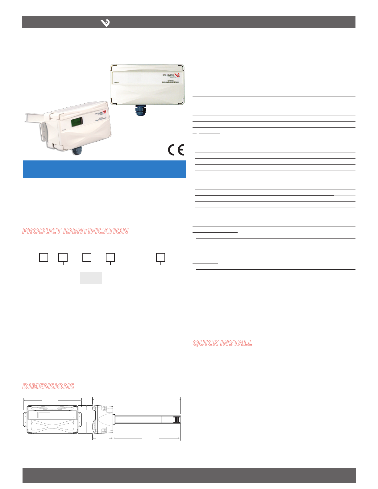
Duct Mounted Environmental CO2Sensors
Installer’s Specifications
Input Voltage 20 to 30VDC, 24AC
Analog Output 4-20mA, (clipped & capped)/0-10VDC (selectable)- CDE models
4-20mA, (clipped & capped)/0-5VDC/0-10VDC (selectable)- CDL models
Sensor Current Draw 100mA Maximum
Operating Temperature Range 0° to 50°C (32° to 122°F)
Housing Material High impact ABS plastic
CO2Transmitter:
Sensor Type Non-dispersive infrared (NDIR), diffusion sampling
Measurement Range 0-2000 ppm or 0-5000 ppm, user selectable on CDL models,
0-2000 ppm on CDE models
Accuracy ±30 ppm ±2% of measured value*
Repeatability ±20 ppm ±1% of measured value
Response Time <60 seconds for 90% step change
RH Transmitter:
HS Sensor Digitally profiled thin-film capacitive (32-bit mathematics); U.S. Patent 5,844,138
Accuracy ±2% from 10 to 80% RH @ 25°C; Multi-point calibration NIST
Hysteresis 1.5% typical
Linearity Included in Accuracy spec.
Stability ±1% @ 20°C (68°F) annually, for two years
Operating Humidity Range 0 to 100% RH
Operating Temperature Range 10° to 35°C (50° to 95°F)
Temperature Coefficient ±0.1% RH/°C above or below 25°C (typical)
Temperature (Transmitter):
Sensor Type Solid-state, integrated circuit
Accuracy ±0.5°C (±1°F) typical
Resolution 0.1°C (0.2°F)
Range 10° to 35°C (50° to 95°F)
Relay Contacts:
1 Form C 1A@30VDC, resistive; 30W max.
Note: Specified accuracy with 24VDC supplied power with rising humidity. RTD/Thermistors in wall
packages are not compensated for internal heating of product.
EMC Conformance: EN 61000-6-3:2001 (Amended by A11:2004) Class B, EN 61000-6-1:2001
EMC Test Methods: CISPR 22:2006, IEC 61000-4-2:2001, IEC 61000-4-3:2006, IEC 61000-4-4:2004,
IEC 61000-4-6:2006, IEC 61000-4-8:2001, IEC 61000-4-11:2004
EMC Special Note: Connect this product to a DC distribution network or an AC/DC power adaptor
with proper Surge protection (EN 61000-6-1:2001 specification requirements).
* Measured at NTP
CD SerieS CD SerieS
NOTICE
• This product is not intended for life or safety applications.
• Do not install this product in hazardous or classified locations.
• Read and understand the instructions before installing
this product.
• Turn off all power supplying equipment before working on it.
• The installer is responsible for conformance to all applicable codes.
CDE
CDL
quick install
Mark and drill the three holes for the duct probe as shown. The centerline must be1.
parallel to the air flow through the duct.
Rotate the duct probe so that its widest surface is perpendicular to the air flow in2.
the duct.
Insert the probe and secure the sensor to the duct with sheet metal screws,3.
making sure that the provided gasket material is compressed between the sensor
housing and the air duct.
Wiring. See wiring diagrams on next page.4.
Product identification
RH Option
H = RH2%
X = NO RH
CDL
DELUXE MODEL:
S
Temp
T = Temp
X = No Temp
(Stop Here)
Sensor Type
A = Transmitter
B = 100R Platinum, RTD
C = 1k Platinum, RTD
D = 10k T2, RTD, Thermistor
E = 2.2k, Thermistor
F = 3k, Thermistor
G = 10k CPC, Thermistor
H = 10k T3, Thermistor
J = 10k Dale, Thermistor
K = 10k w/11k shunt, Thermistor
M = 20k NTC, Thermistor
N = 1800 ohm, Thermistor
R = 10k US, Thermistor
S = 10k 3A221, Thermistor
T = 100k, Thermistor
U = 20k “D”, Thermistor
Optional Cal Cert.
Blank = None
1 = 1 pt Temp Cert
2 = 2 pt Temp Cert
CDE (no options)
ECONOMY MODEL:
dimensions
6.7"
(170 mm)
3.1"
(78 mm)
7.8"
(97 mm)
2.4"
(61 mm)
10.2"
(258 mm)


