manuals.online logo
Brands
  1. Home
  2. •
  3. Brands
  4. •
  5. Veris Industries
  6. •
  7. Transducer
  8. •
  9. Veris Industries PW2 Series User manual

Veris Industries PW2 Series User manual

Z204201-0H Page 1 of 3 ©2018 Veris Industries USA 800.354.8556 or +1.503.598.4564 / suppor[email protected] 1018
Alta Labs, Enercept, Enspector, Hawkeye, Trustat, Aerospond, Veris, and the Veris ‘V’ logo are trademarks or registered trademarks of Veris Industries, L.L.C. in the USA and/or other countries.
Other companies’ trademarks are hereby acknowledged to belong to their respective owners.
NOTICE
• This product is not intended for life or safety applications.
• Do not install this product in hazardous or classied locations.
•
Read and understand the instructions before installing this product.
• Turn o all power supplying equipment before working on it.
• The installer is responsible for conformance to all applicable codes.
If this product is used in a manner not specied by the manufacturer, the protection
provided by the product may be impaired. No responsibility is assumed by the
manufacturer for any consequences arising out of the use of this material.
Installation Guide
Pressure TM
Product Identication
Specications
Product Overview
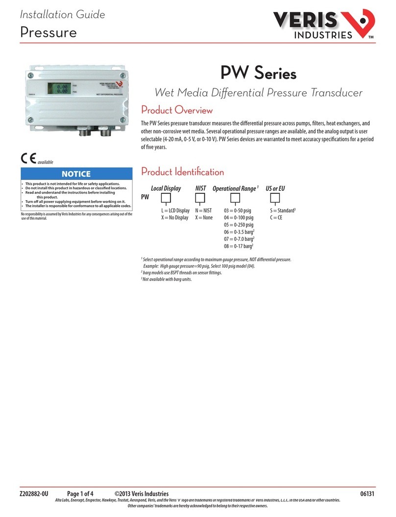
The PW2 Series sensor is designed to accept high dierential pressure. Install the sensor on a duct or pipe across a
pump, lter, heat exchanger, compressor, or other non-corrosive wet media. The dual sensor design eliminates the
need for a bypass valve, and the bi-directional capability reduces installation errors. A pushbutton allows easy zero
adjustment.
PW2 Series
Wet Media Differential Pressure Transducer
Local Display
L = LCD Display
X = No Display
NIST
N = NIST
X = None
CE
S = Standard
Operational Range*
03 = 0 to 50 psig
04 = 0 to 100 psig
05 = 0 to 250 psig
PW2
* IMPORTANT!
Select operational range according to maximum gauge pressure, NOT dierential pressure.
Example: High gauge pressure=90 psig, select 100 psig model (04).
Media Compatibility 17-4 PH stainless steel
Input Power 12 to 24 Vdc, 29 mA max.; loop powered
Output 2-wire transmitter; 4 to 20 mA (clipped and capped)
Proof Pressure 2x max. F.S. range
Burst Pressure 5x max. F.S. range
Accuracy at 25 °C* Ranges A, B, C: ±1% F.S.**
Range D: ±2% F.S.**
Surge Damping Electronic; 5-second averaging
Temperature Compensated
Range
0 to 50 °C (32 to 122 °F);
TC Zero <1.5% of product F.S. per sensor
TC Span <1.5% of product F.S. per sensor
Sensor Operating Range -20 to 85 °C (-4 to 185 °F)
Long Term Stability ±0.25% per year
Zero Adjust Pushbutton auto-zero
Operating Environment -10 to 55 °C (14 to 131 °F); 10 to 90% RH non-condensing
Fittings 1/8” NPT female thread, stainless steel 17-4 PH
Physical White powder-coated aluminum
PRESSURE RANGES
0 to 50 psi (0 to 3.45 bar) 5/10/25/50 psid (0 to 0.34/0.69/1.72/3.45 bar)
0 to 100 psi (0 to 6.89 bar) 10/20/50/100 psid (0 to 0.69/1.38/3.45/6.89 bar)
0 to 250 (0 to 17.24 bar) 25/50/125/250 psid (0 to 1.72/3.45/8.62/17.24 bar)
Note: To conform to EMC standards, use shielded cabling. Technical information is available from the factory on
request.
* Accuracy combines linearity, hysteresis, and repeatability.
** F.S. is defined as full span of selected range in bidirectional mode.
Z204201-0H Page 2 of 3 ©2018 Veris Industries USA 800.354.8556 or +1.503.598.4564 / suppor[email protected] 1018
Alta Labs, Enercept, Enspector, Hawkeye, Trustat, Aerospond, Veris, and the Veris ‘V’ logo are trademarks or registered trademarks of Veris Industries, L.L.C. in the USA and/or other countries.
Other companies’ trademarks are hereby acknowledged to belong to their respective owners.
TM
PW2 Series Installation Guide
2.2"
(57 mm)
4"
(102 mm)
5.8"
(147 mm)
LOW HIGH
WET DIFFERENTIAL PRESSURE
Dimensions
Installation Observe precautions for handling static sensitive
devices to avoid damage to the circuitry that
is not covered under the factory warranty.
1. Mount sensor on a duct or pipe, across the pump, lter, or other pressure dierential.
2. Wire as shown below.
DIGITAL CONTROL
Digital Output
4-20mA IN
POWER SOURCE
12 to 24 VDC
Port Swap/Norm
Bi-Dr/Normal
Slow Avg/Fast Norm
Analog Rev/Norm
Bar/PSI
ZERO A-High
B-Mid High
C-Mid Low
D-Low
REMOTE
ZERO
4-20mA
Pressure
Range Settings
Polarity
Insensitive
Default Settings in bold.
Insert jumper to activate
other features.
Model
PW2-03
PW2-04
PW2-05
A
50
100
250
B
25
50
125
C
10
20
50
D
5
10
25
Model
PW2-03
PW2-04
PW2-05
A
3.45
6.89
17.24
B
1.72
3.45
8.62
C
0.69
1.38
3.45
D
0.34
0.69
1.72
Range (PSI)
Range (bar)
HI PORT
100 psi
100 psi
50 psi
50 psi
0 psi
LO PORT
0 psi
50 psi
50 psi
100 psi
100 psi
4-20mA
+100 psi
+50 psi
0 psi
-50 psi
-100 psi
Bidirectional Operation
Input Conditions Result Outputs Read
DP
20mA
16mA
12mA
8mA
4mA
Output is mA only.
Example: PW2-04
Optional: Connect Zero terminals to digital output (contact
closure) of control system.
Caution: Zero input is for dry-contact only. Do not apply voltage to
the Zero terminals.
Range: Use the Range switch to select
F.S. dierential pressure.
Note: Use of
a housing
grounding screw
is required for CE
applications
Z204201-0H Page 3 of 3 ©2018 Veris Industries USA 800.354.8556 or +1.503.598.4564 / suppor[email protected] 1018
Alta Labs, Enercept, Enspector, Hawkeye, Trustat, Aerospond, Veris, and the Veris ‘V’ logo are trademarks or registered trademarks of Veris Industries, L.L.C. in the USA and/or other countries.
Other companies’ trademarks are hereby acknowledged to belong to their respective owners.
TM
PW2 Series Installation Guide
Installation (cont.)
Operation
Jumper Notes
Port Swap/Norm Reverses polarity of the pressure ports (i.e. makes the LO port operate as the HI port and vice versa); used when the
sensor is incorrectly plumbed.
Bi-Dr/Normal Normal: 0 to F.S. pressure
Bidirectional: -F.S. pressure to +F.S. pressure; output reads 1/2 when pressure is zero.
Slow Avg/Fast Norm Slow mode provides 5-second averaging for surge damping.
Analog Rev/Norm Normal: Output increases as pressure increases;
Reverse: Output is maximum when pressure dierential is zero and decreases as pressure increases.
Bar/PSI Select output units.
Auto-Zero: Press and hold the Zero button for two seconds or provide contact closure on the auxiliary ‘Remote Zero’ terminal to
reset the output to zero pressure. To protect the device from accidental zeroing, this feature is only enabled when the detected
pressure is within 5% of factory calibration.
3. Congure the jumpers as described below.

This manual suits for next models

9

Other Veris Industries Transducer manuals

Veris Industries PH Series User manual

Veris Industries

Veris Industries PH Series User manual

Veris Industries PWR Series User manual

Veris Industries

Veris Industries PWR Series User manual

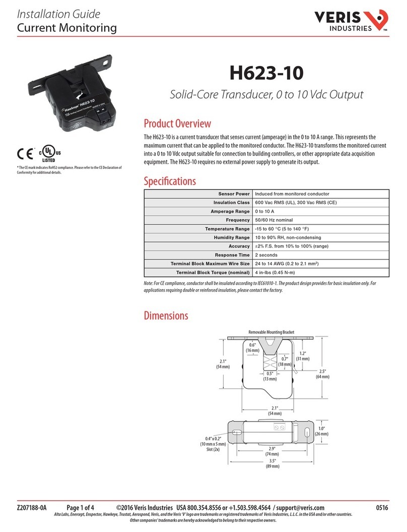
Veris Industries H623-10 User manual

Veris Industries

Veris Industries H623-10 User manual

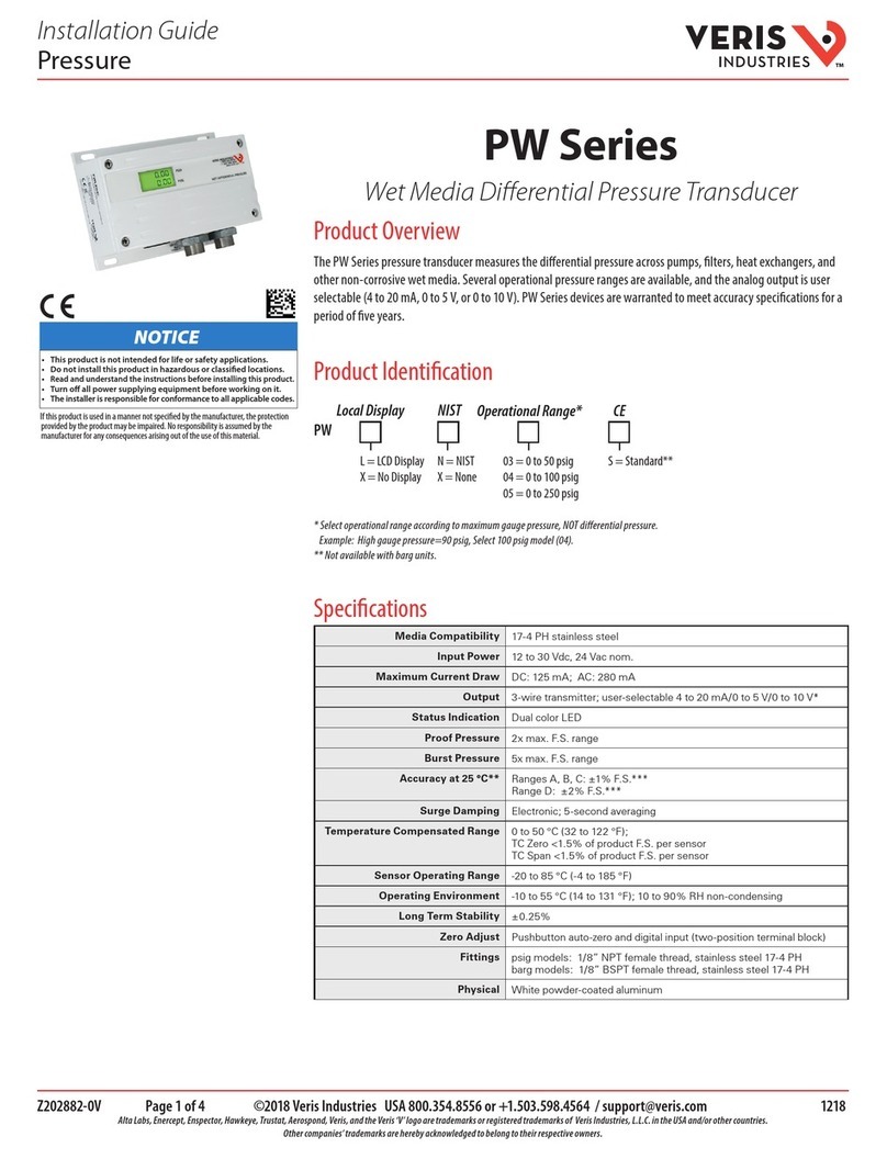
Veris Industries PW Series User manual

Veris Industries

Veris Industries PW Series User manual

Veris Industries H622-20 User manual

Veris Industries

Veris Industries H622-20 User manual

Veris Industries PWXN07C User manual

Veris Industries

Veris Industries PWXN07C User manual

Veris Industries PW Series User manual

Veris Industries

Veris Industries PW Series User manual

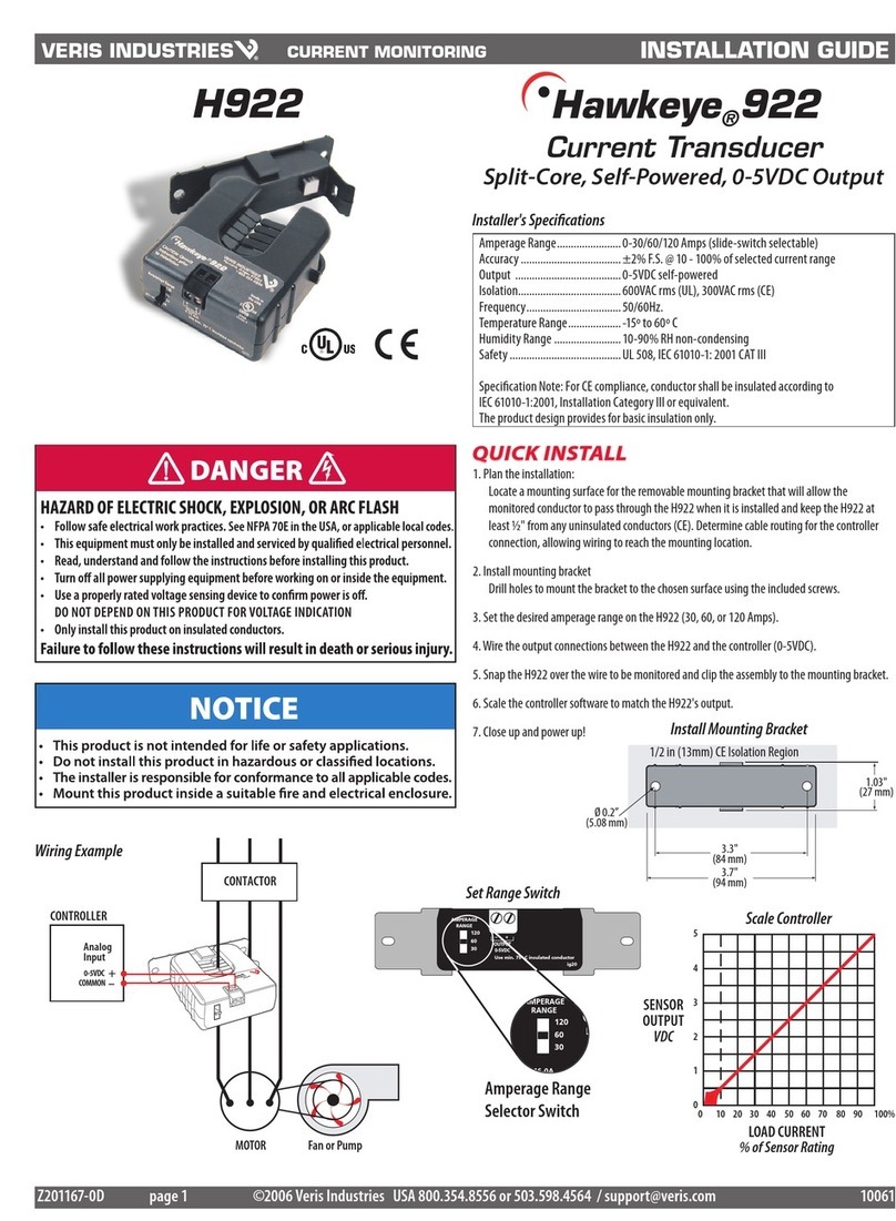
Veris Industries Hawkeye 922 User manual

Veris Industries

Veris Industries Hawkeye 922 User manual

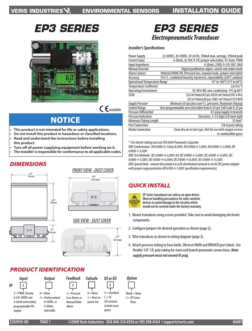
Veris Industries EP3 Series User manual

Veris Industries

Veris Industries EP3 Series User manual

Veris Industries ENERCEPT H8035 User manual

Veris Industries

Veris Industries ENERCEPT H8035 User manual

Veris Industries Hawkeye H720 User manual

Veris Industries

Veris Industries Hawkeye H720 User manual

Veris Industries PW Series User manual

Veris Industries

Veris Industries PW Series User manual

Popular Transducer manuals by other brands

Capetti Elettronica Winecap EXP2PUL user manual

Capetti Elettronica

Capetti Elettronica Winecap EXP2PUL user manual

Licht MFC-400/I-VAC Technical manual

Licht

Licht MFC-400/I-VAC Technical manual

Ametek 953N Series Configuration manual

Ametek

Ametek 953N Series Configuration manual

aci EPC Installation and operation instructions

aci

aci EPC Installation and operation instructions

Balluff BTL7-S5 B-M Series Condensed guide

Balluff

Balluff BTL7-S5 B-M Series Condensed guide

Metrix 5485C installation manual

Metrix

Metrix 5485C installation manual

HYDACELECTRONIC HDA 4800 user manual

HYDACELECTRONIC

HYDACELECTRONIC HDA 4800 user manual

red lion CTL12S manual

red lion

red lion CTL12S manual

Caen ELS Flucs CT -100 user manual

Caen ELS

Caen ELS Flucs CT -100 user manual

Siemens Echomax XCT-8 operating instructions

Siemens

Siemens Echomax XCT-8 operating instructions

TorqSense SGR510 Series user manual

TorqSense

TorqSense SGR510 Series user manual

GE T17 installation guide

GE

GE T17 installation guide

WIKA CPD8500 Utility manual

WIKA

WIKA CPD8500 Utility manual

DAIICHI QT2-500 instruction manual

DAIICHI

DAIICHI QT2-500 instruction manual

Magpowr IP-80 instruction manual

Magpowr

Magpowr IP-80 instruction manual

M-system L2CA instruction manual

M-system

M-system L2CA instruction manual

Rishabh RISH CON - V operating manual

Rishabh

Rishabh RISH CON - V operating manual

Setra Systems 278 installation guide

Setra Systems

Setra Systems 278 installation guide

manuals.online logo
manuals.online logoBrands
  • About & Mission
  • Contact us
  • Privacy Policy
  • Terms and Conditions

Copyright 2025 Manuals.Online. All Rights Reserved.