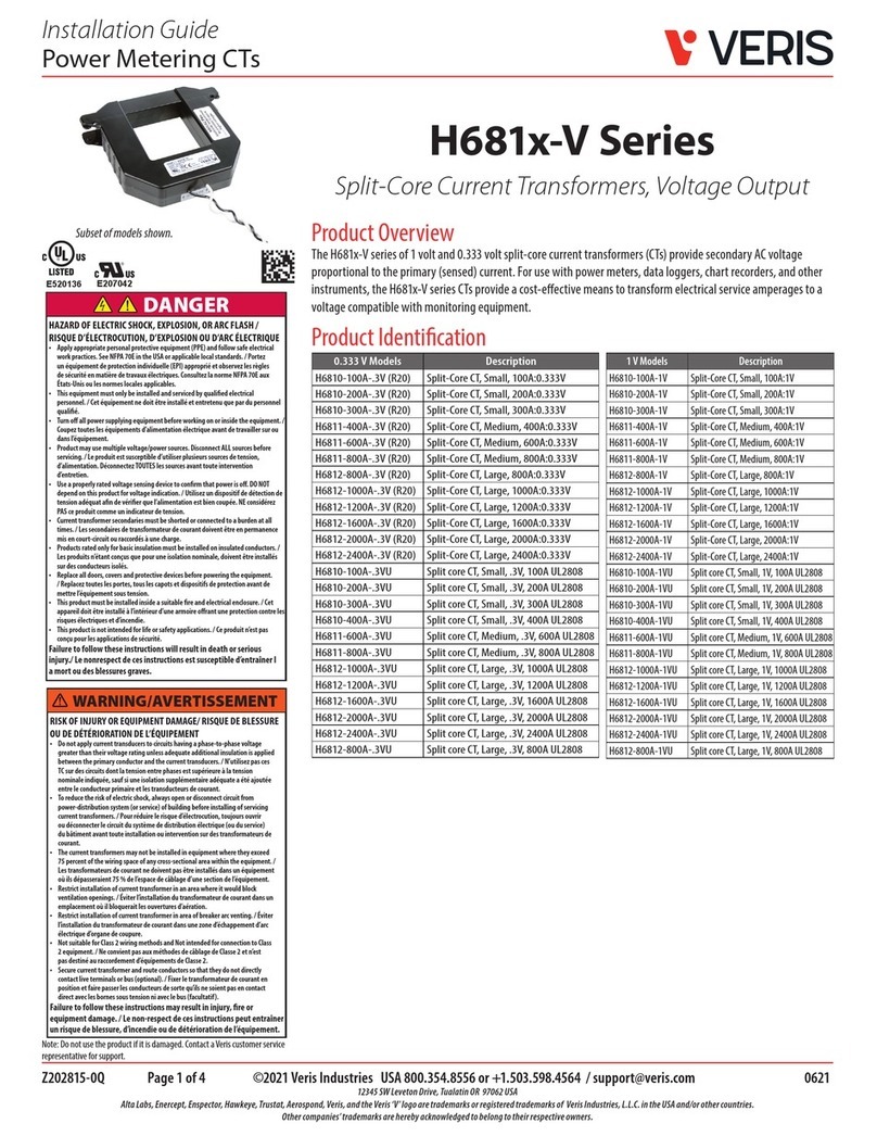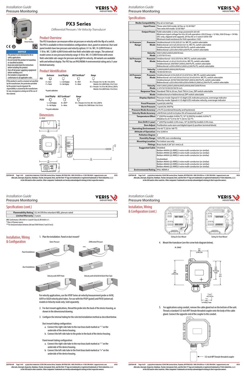
1/16Z207085-0C
Regulatory Information / Información reglamentaria / Informations réglementaires / 法规信息 /
Gesetzlich vorgeschriebene Informationen
2
1
Enercept FLEX
TM E20 Series E20 Series compact power and energy meters (uni-directional, bi-
directional, Modbus and BACnet). To download the Modbus Point Map,
BACnet Object List, Conguration Tool and additional documentation,
visit www.veris.com.
E20 Series Medidores compactos de potencia y energía Serie E20
(unidireccionales, bidireccionales, Modbus y BACnet). Para descargar
elmapa de puntos Modbus, la lista de objetos BACnet, la herramienta
deconguración y documentación adicional, visite www.veris.com.
Série E20 compteur d’énergie et de puissance compacte (uni-directionel,
bi-directionnel, Modbus et BACnet). Pour télécharger Modbus Point
Map, la liste d’objets BACnet, l’outil de conguration ainsi que la
documentation supplémentaire, visitez www.veris.com.
1
E20 系列 紧凑型电力电能表(单向、双向、Modbus和BACnet协议)。
如下载Modbus Point Map、BACnet Object List、Conguration Tool和其
他文件,请访问www.veris.com。
A qualified person is one who has skills and knowledge related to the construction and operation of this
electrical equipment and installations, and has received safety training to recognize and avoid the hazards
involved. NEC Article 100
If this product is used in a manner not specified by the manufacturer, the protection provided by the product
may be impaired. No responsibility is assumed by the manufacturer for any consequences arising out of the
use of this material.
DANGER
HAZARD OF ELECTRIC SHOCK, EXPLOSION, OR ARC FLASH
• This product must be installed inside a suitable fire and electrical enclosure.
• Follow safe electrical work practices. See NFPA 70E in the USA, or applicable local codes.
• This equipment must only be installed and serviced by qualified electrical personnel.
• Do not use this product for life or safety applications.
• Do not install this product in hazardous or classified locations.
• Read, understand and follow the instructions before installing this product.
• Turn off all power supplying equipment before working on or inside the equipment.
• Product may use multiple voltage/power sources.
Disconnect ALL sources before servicing.
• Use a properly rated voltage sensing device to confirm that power is off. DO NOT depend on this product
for voltage indication.
• Current transformer secondaries (current mode) must be shorted or connected to a burden at all times.
• Products rated only for basic insulation must be installed on insulated conductors.
• Replace all doors, covers and protective devices before powering the equipment.
• The installer is responsible for conformance to all applicable codes.
Failure to follow these instructions will result in death or serious injury.
For use in a Pollution Degree 2 or better environment only. A Pollution Degree 2 environment must control conductive
pollution and the possibility of condensation or high humidity. Consider the enclosure, the correct use of ventilation,
thermal properties of the equipment, and the relationship with the environment.
Provide a disconnect device to disconnect the meter from the supply source. Place this device in close proximity to the
equipment and within easy reach of the operator, and mark it as the disconnecting device. The disconnecting device shall
meet the relevant requirements of IEC 60947-1 and IEC 60947-3 and shall be suitable for the application. In the US and
Canada, disconnecting fuse holders can be used. Provide overcurrent protection and disconecting device for supply
conductors with approved current limiting devices suitable for protecting the wiring.
WARNING
LOSS OF CONTROL
• Assure that the system will reach a safe state during and after a control path failure.
• Separate or redundant control paths must be provided for critical control functions.
• Test the effect of transmission delays or failures of communication links.1
• Each implementation of equipment using communication links must be individually and thoroughly tested for proper
operation before placing it in service.
Failure to follow these instructions may cause injury, death or equipment
damage.
Control system design must consider the potential failure modes of control paths and, for certain critical control functions,
provide a means to acheive a safe state during and after a path failure. Examples of critical control functions are emergency
stop and over-travel stop.
1For additional information about anticipated transmission delays or failures of the link, refer to NEMA ICS 1.1 (latest
edition). Safety Guidelines for the Application, Installation, and Maintenance of Solid-State Controls or its equivalent in your
specific country, language, and/or location.
FCC PART 15 INFORMATION
NO
TE: This equipment has been tested by the manufacturer and found to comply with the limits for a class A digital
device, pursuant to part 15 of the FCC Rules. These limits are designed to provide reasonable protection against
harmful interference when the equipment is operated in a commercial environment. This equipment generates,
uses, and can radiate radio frequency energy and, if not installed and used in accordance with the instruction
manual, may cause harmful interference to radio communications. Operation of this equipment in a residential
area is likely to cause harmful interference in which case the user will be required to correct the interference at
his own expense. Modifications to this product without the express authorization of the manufacturer nullify
this statement.
1. The CE mark indicates RoHS2 compliance. Please refer to the CE Declaration of Conformity for additional
details. / La marca CE indica cumplimiento de la RoHS2. Para información adicional, consulte la Declaración
de conformidad con CE. / Le marquage CE indique la conformité RoHS2. Pour plus de détails, veuillez vous
reporter à la Déclaration de conformité CE. / CE认证标志表示符合RoHS2标准。更多详情,请参阅《欧盟
符合性声明》(CE Declaration of Conformity)。/ Das CE-Zeichen steht für die Einhaltung der RoHS2. Für
weitere Details siehe die EG-Konformitätserklärung für die CE-Kennzeichnung.
A
A
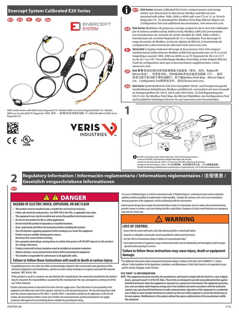
RS-485 connector, strain relief multi-tool, 120 Ω terminating resistor. /
Conector RS-485, herramienta múltiple liberadora de tensión,
resistor de terminación de 120 Ω. / Connecteur RS-485, réducteur de tension,
résistance de terminaison 120 Ω. / RS-485ஏධȂሥקᄂڼቂનȂ120 ΩޤݢᏟධ /
RS-485-Verbindung, Multifunktionswerkzeug zur Zugentlastung,
120 Ω Abschlusswiderstand.
1/22Z207085-0A
SafetyPrecautions /
2
1
EnerceptFLEX
TM
E20 Series
E20Seriescompactpower and engergy meters (uni-directional, bi-
directional,ModbusandBACnet). To download the Modbus Point Map,
BACnetObjectList,Configuration Tool and additional documentation,
visittheVeriswebsite at www.veris.com.
E20Seriescompactpower and engergymeters (uni-directional, bi-
directional,ModbusandBACnet). Todownload the Modbus Point Map,
BACnetObjectList,Configuration Tool and additional documentation,
visittheVeriswebsite at www.veris.com.
E20Seriescompactpower and engergymeters (uni-directional, bi-
directional,ModbusandBACnet). Todownload the Modbus Point Map,
BACnetObjectList,Configuration Tool and additional documentation,
visittheVeriswebsite at www.veris.com.
1.TheCEmarkindicates RoHS2compliance. Please refer to the CEDeclaration ofConformity for additional
details./
1
A
A
ModelName:
TestParameters:
RatedCurrent:
CalibrationDate:
DigitalInput:
RelayTerminal:
TestLoad
Parameter-V,A&F
Vavg
AavgFV
avgA
av
gFVavg
Aavg
F
Parameter-W
hU
PF
0.5Lag
0.8Lead
UPF0
.5La
g0.8Lead
UPF
Notes:
1.TheCertificateshallnotbere
roducedexce
tinfull
without
riorwritten
a
rovaloftheissui
n
authorit
-0.0
4
0.01
230V,1.0
A
0.0
5
±0.
6±0.
6
63.5V,5.0A
FirmwareRevision:
Communication:
DigitalOutput:
-0.0
4
AccuracyClass:
PM5330
V,A,F,Wh
/5A,/1A
18-Apr-1
3
Pass
0.0
4
±0.
5
347V,0.1
A
3410000
1
0.0
1±0.
5±0.100.0
3
±0.
5
:01.02.00
RS485
PermissibleError(%)
0.0
1
ObservedError(%)@60Hz
±0.10
ObservedError(%)@50Hz
0.5La
g
5
0
.
0
40
.0 0.0
5
Pass
Pass
±1.0
0.04
0.0
5
0.03
ClassX.X
0.0
0±0.
5
0.0
1±0.
5
±0.
5
±0.
5
ObservedError(%)-Wh
@60Hz
±0.10
0.0
30.0
1
±0.6
0.010.0
30.01
0.00
0.0
1
ObservedError(%)-Wh
@50Hz
-0.0
50
PermissibleError(%)
±0.
5±
0.
60.0
0
5
0.0
0
5
0
.0
-0.0
5
0.0
1
0.01
0.0
0
0.0
4
±1.
.
Po
w
e
r
L
o
g
i
c
™
P
M
5
3
0
0PM
5
3
0
0
s
e
ri
e
s
p
o
we
r
a
n
d
e
ne
r
g
y
m
e
te
r
T
o
d
o
wnlo
a
d
u
se
rma
n
u
a
ls
a
n
d
o
t
h
e
r
d
o
c
u
m
e
n
t
a
t
io
n
,
vi
s
i
t
ww
w
.s
c
h
n
e
i
d
e
r
-
e
l
ect
r
i
c
.
co
m
.
T
y
p
e
t
h
e
d
e
vi
ce
m
o
d
e
l
(
fo
r
e
.
g
.
,
P
M
5
3
41
)in
t
h
e
s
e
a
rc
h
e
ld
.
R
e
fe
r
t
o
t
h
e
u
s
e
r
g
u
id
e
wh
e
n
y
o
u
se
e
t
h
is
icon
.
A
B
D
A
N
G
E
R
/
P
E
L
I
G
R
O
/
D
A
N
G
E
R
/
G
E
F
R
I
E
S
G
O
D
E
D
E
S
C
A
1
C
e
nt
ra
l
de
me
d
i
d
a
d
e
po
t
e
n
c
i
a
y
e
n
e
rg
ía
d
e
l
a
s
e
ri
e
P
M5
3
0
0
e
s
te
i
co
n
o
.
A
pp
a
re
i
l
de
m
e
s
u
re
d’
é
lec
tri
c
i
t
é
e
t
d’
é
n
e
rg
i
e
s
é
r
i
e
P
M
5
3
0
0
L
e
ist
ung
s
-
u
n
d
E
n
erg
i
e
m
e
s
s
g
e
rä
t
der
Re
ihe
P
M
5
3
0
0
M
od
e
l
/
M
o
d
e
l
o
/
m
o
d
e
l
o
/
м
о
д
е
л
ь
/
P
M
5
3
1
0–
P
M
5
3
3
0–
PM
5
3
3
1–
P
M
5
3
2
0–
P
M
5
3
40–
P
M
5
3
4
1–
H
R
B
67
985
(
P
M5
3
3
0
&
P
M
5
3
3
1
)
/
H
R
B
73
3
03
(
P
M
5
3
1
0
)
/
H
R
B
7
3
3
0
5
(P
M5
3
2
0
)
/
H
R
B
67
9
87
(
P
M
5
3
4
0
&
P
M5
3
4
1)
H
R
B
7
30
70
Co
n
t
a
tor
e
di
p
o
t
e
nza
e
d
a
l
si
t
o
w
w
w
.
s
ch
n
e
id
e
r
-
e
le
ct
r
i
c
.
c
o
m
mo
d
e
l
lo
d
el
d
i
s
p
o
s
i
t
ivo
(a
d
e
s.
P
M5
3
d
iri
ce
r
c
a
.
M
e
d
idor
d
e
pot
ên
c
i
a
e
e
n
e
rg
i
a
s
d
o
c
u
m
e
n
t
o
s,
v
i
s
it
e
o
s
i
te
ww
w
.s
В
а
т
тт
т
P
M
5
3
0
0
Чт
о
б
ы
с
к
а
ч
а
т
ь
р
ук
о
в
одс
т
и
н
ф
о
рм
а
цию
,
по
с
е
т
ит
е
Н
а
б
ер
ит
е
м
о
д
е
ль
у
с
т
р
о
п
о
л
е
по
и
с
к
а
.
Е
сл
и
ув
и
д
и
т
е
р
ук
о
в
о
дс
т
в
о
P
M5
3
0
0
e
l
e
c
tr
i
c
.
c
o
m
P
M5
3
4
1
fty
P
reca
u
tio
n
s
/P
r
e
c
a
u
c
io
n
e
s
d
es
e
g
u
r
id
a
d
/Me
s
u
r
es
d
e
s
é
c
u
r
i
té
H
RB6
9
8
8
7
-
RJ-45connector,strainrelief, jumper./
E20㌱ࡍ⭫࣑৸ᮦф⭫㜳⎁䠅Ԡ༷රᆇ⇥ѝ䭞ޕᩌ㍒ᆇ
㾱л䖭⭘ᡧ઼ަᆳ᮷ẓˈ䈧䇯㾱л䖭⭘ᡧ઼ަᆳ䈧৲㘳
൘ᩌ㍒ᆇ⇥ѝ䭞ޕ䇮༷ර˄ֻྲᆇ⇥ѝ䭞ޕ䇮༷රᆇ⇥ѝ䭞ޕ
ྲⴻ㿱↔മḷˈ䈧৲㘳⭘ᡧᤷইwww.veris.comDŽ
DANGER/ PELIGRO / DANGER / GEFAHR
HAZARDOFELECTRIC SHOCK, EXPLOSION, ORARC FLASH
Applyappropriatepersonalprotective equipment (PPE) and follow safe electrical work
practices.SeeNFPA70E in the USAor applicable local standards.
Turnoffall power supplying this device before working on it.
Donotexceed the device’s ratings for maximum limits.
Donotuse this device for critical control or protection applications where human or
equipmentsafetyrelies on the operation of the control circuit.
Alwaysusegrounded external CTsfor current inputs.
Failuretofollow these instructions will result in death or serious injury.
RIESGODEDESCARGAELÉCTRICA,EXPLOSIÓNO DESTELLO DE ARCO
Utiliceunequipo de protección individual adecuado (EPI) y siga las prácticas de seguridad
detrabajoseléctricos. Consulte la normativa NFPA 70Epara los EE.UU. o la normativa
localaplicable.
Antesdeiniciar cualquier operación con el dispositivo, apague todas sus fuentes de
alimentación.
totalmenteapagado.
Nosobrepaselos límites máximos de los valores nominales del dispositivo.
Noutiliceeste dispositivoen aplicaciones críticas de control o protección en lasque la
seguridaddelas personaso equiposdependa del funcionamiento delcircuito de control.
UtilicesiempreTI externos con terminal a tierra para las entradas de intensidad.
Elincumplimientode estas instrucciones ocasionará la muerte o lesiones de gravedad.
RISQUED’ÉLECTROCUTION,D’EXPLOSIONOU D’ARC ÉLECTRIQUE
Portezunéquipement de protection individuelle (EPI) approprié et observez les règles
desécuritéen matière de travaux électriques. Consultez la norme NFPA 70E aux États-
Unisoules normes locales applicables.
Coupeztoutealimentation avant de travailler sur ou danscet appareil.
Utiliseztoujoursun dispositif de détection de tension à valeur nominale appropriée pour
vousassurerque l’alimentation est coupée.
Nedépassezpas les valeurs nominalesde l’appareil, qui constituent les limites
maximales.
N’utilisezpascet appareilpour lesapplications critiquesde commande ou de protection
danslesquelleslasécurité du personnel ou de l’équipement dépend du fonctionnement
ducircuitde commande.
UtiliseztoujoursdesTC externes mis à la terre pour les entrées de courant.
Lenon-respectde ces instructions entraînera la mort ou des blessures graves.
GEFAHREINESELEKTRISCHEN SCHLAGS, EINER EXPLOSION ODER EINES
LICHTBOGENÜBERSCHLAGS
TragenSiegeeignete persönliche Schutzausrüstung (PSA) und befolgen Sie sichere
ArbeitsweisenfürdieAusführung von Elektroarbeiten. Beachten Sie die Norm NFPA70E (in
denUSA)sowiedie einschlägigen örtlichen Standards.
SchaltenSiejede Spannungsversorgung ab, bevorSie Arbeiten am Gerät vornehmen.
VerwendenSiestets ein genormtes Spannungsprüfgerät, um festzustellen, ob die
Spannungsversorgungwirklichausgeschaltet ist.
ÜberschreitenSienichtdie maximalen Bemessungsgrenzwerte des Geräts.
DiesesGerätdarfnicht für kritische Steuerungs- oder Schutzanwendungen verwendet
werden,beidenen die Sicherheit von Personen und Sachwerten von der Funktion des
Steuerkreisesabhängt.
FürdieStromeingänge sind stets externe, geerdete Stromwandler zu verwenden.
NichtbeachtungdieserAnweisungen führt zu schweren bzw. tödlichenVerletzungen.
E20 Serie kompakte Leistungs- und Energiemessgeräte (unidirektional,
bidirektional, Modbus und BACnet). Die Modbus Point Map, die BACnet
Objektliste, das Kongurations-Tool und zusätzliche Unterlagen können
Sie auf www.veris.com herunterladen.
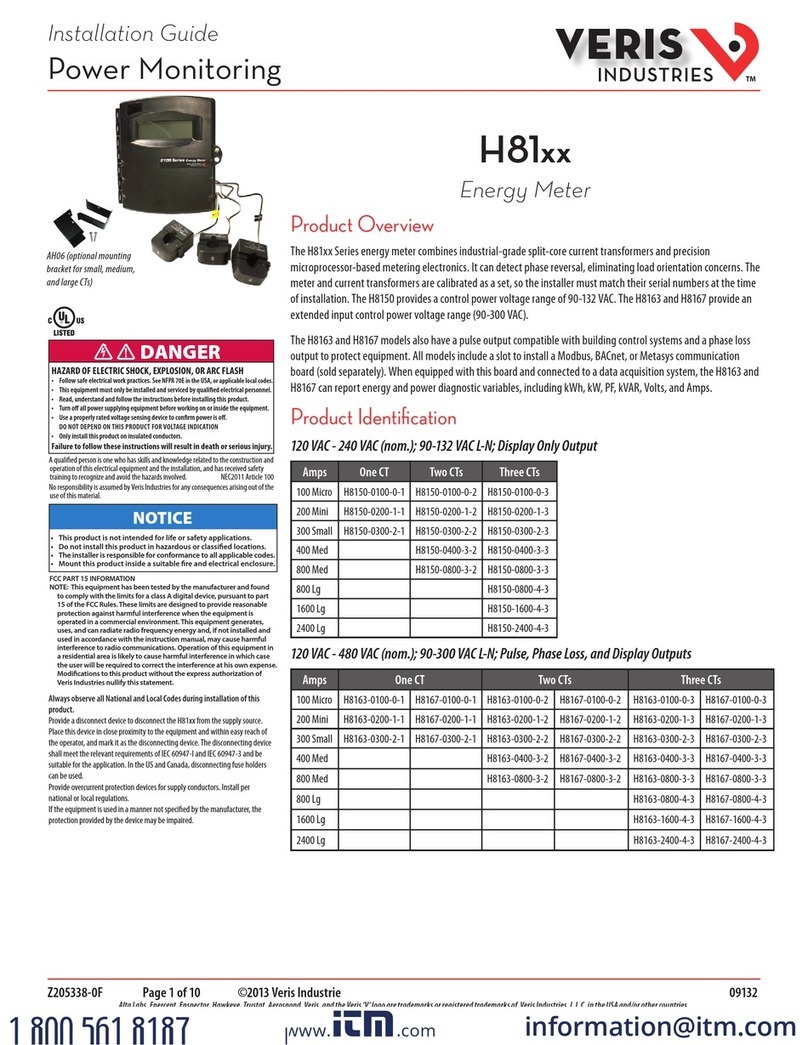
ANSI model shown with E683 Series Rogowski CTs (sold separately) /
Modelo ANSI con Series Rogowski E683 CTs (se venden por separado) /
Modèle ANSI avec la série E683 TC Rogowski (vendu séparément) /
ANSI 型号 – 使用E683系列罗氏线圈 CT (分开售卖) /
ANSI-Modell mit E683 Serie Rogowski CTs (separat erhältlich)
