manuals.online logo
Brands
  1. Home
  2. •
  3. Brands
  4. •
  5. Veris
  6. •
  7. Measuring Instrument
  8. •
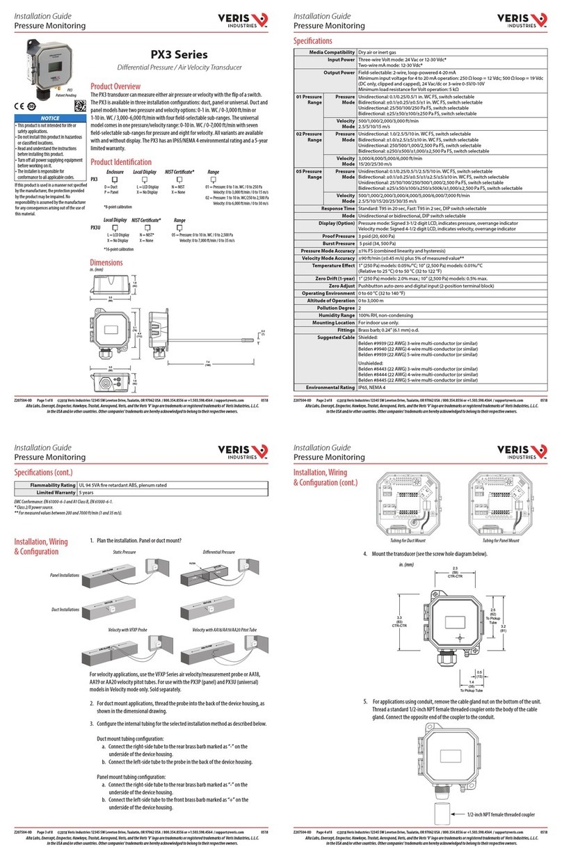
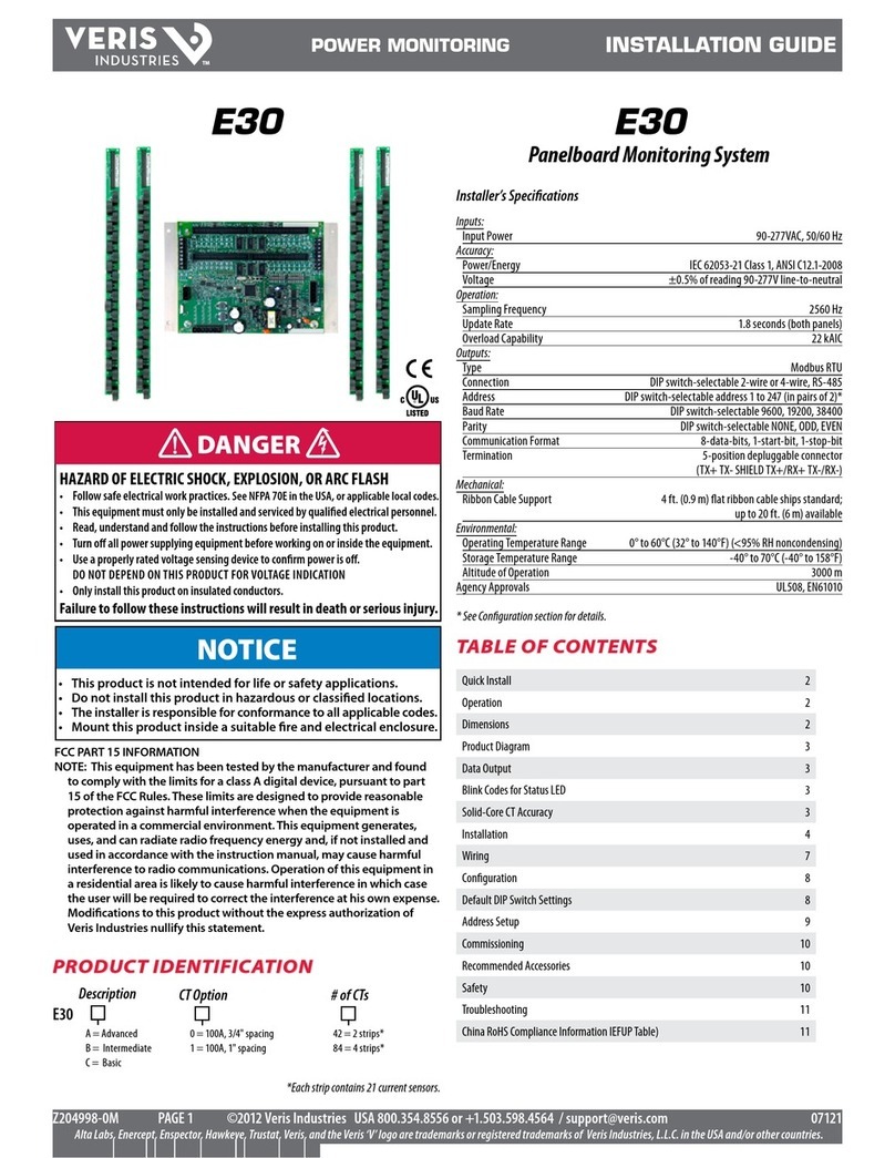
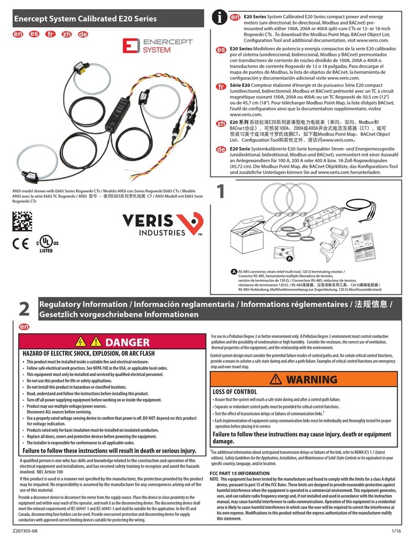
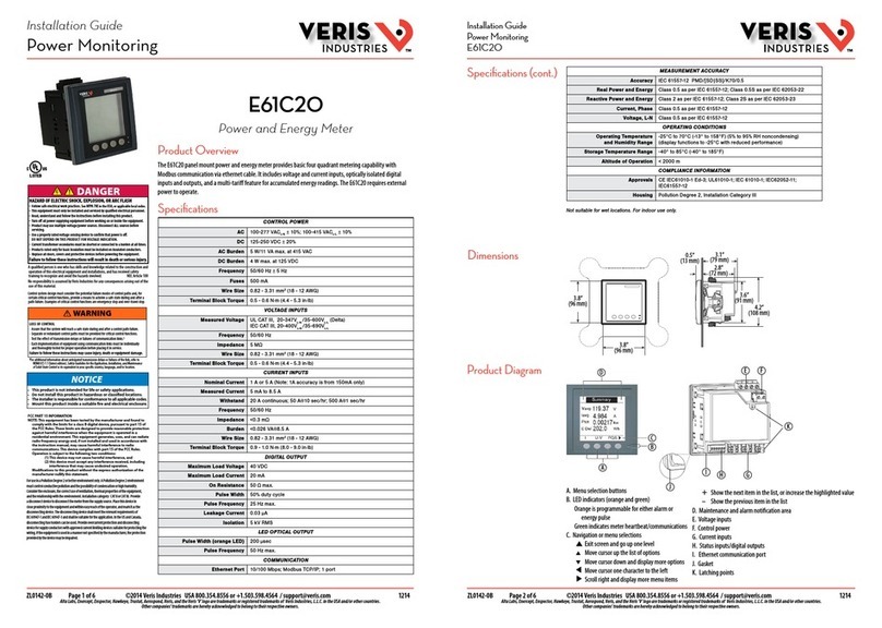
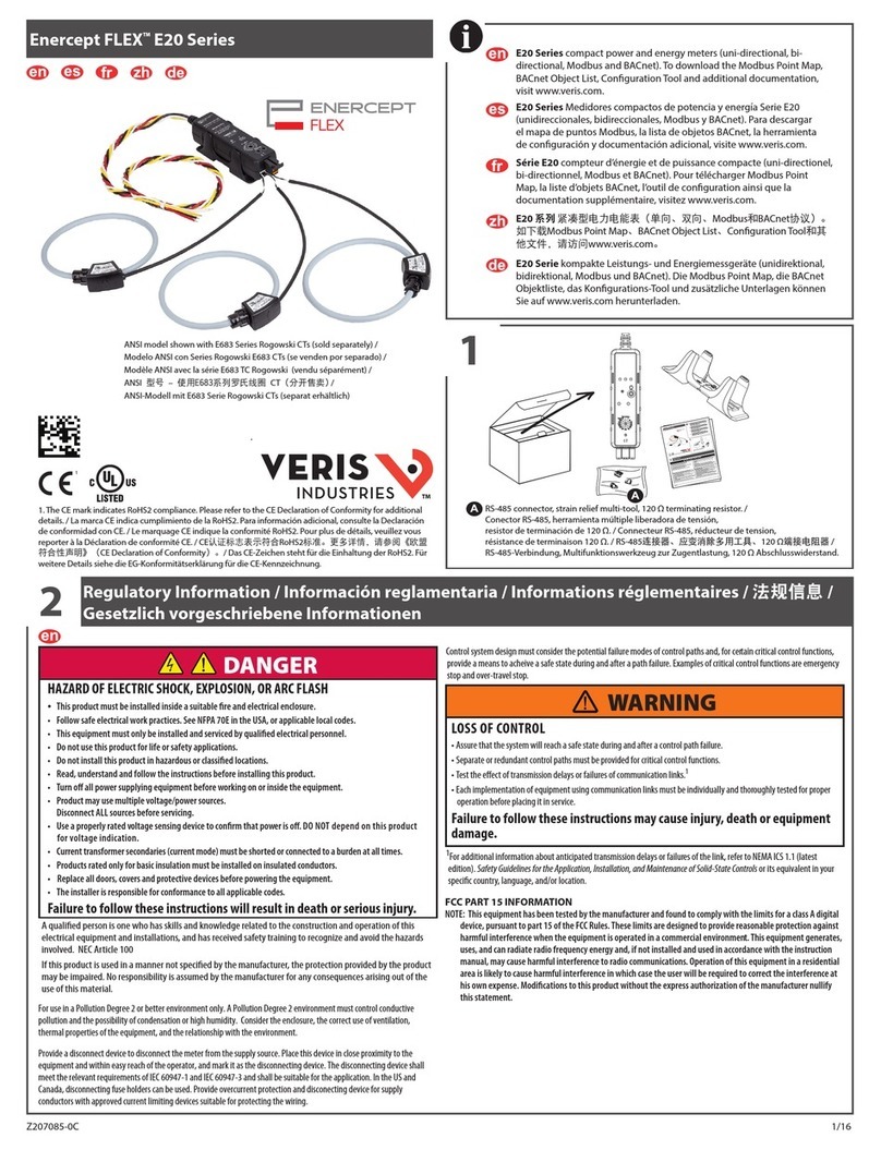
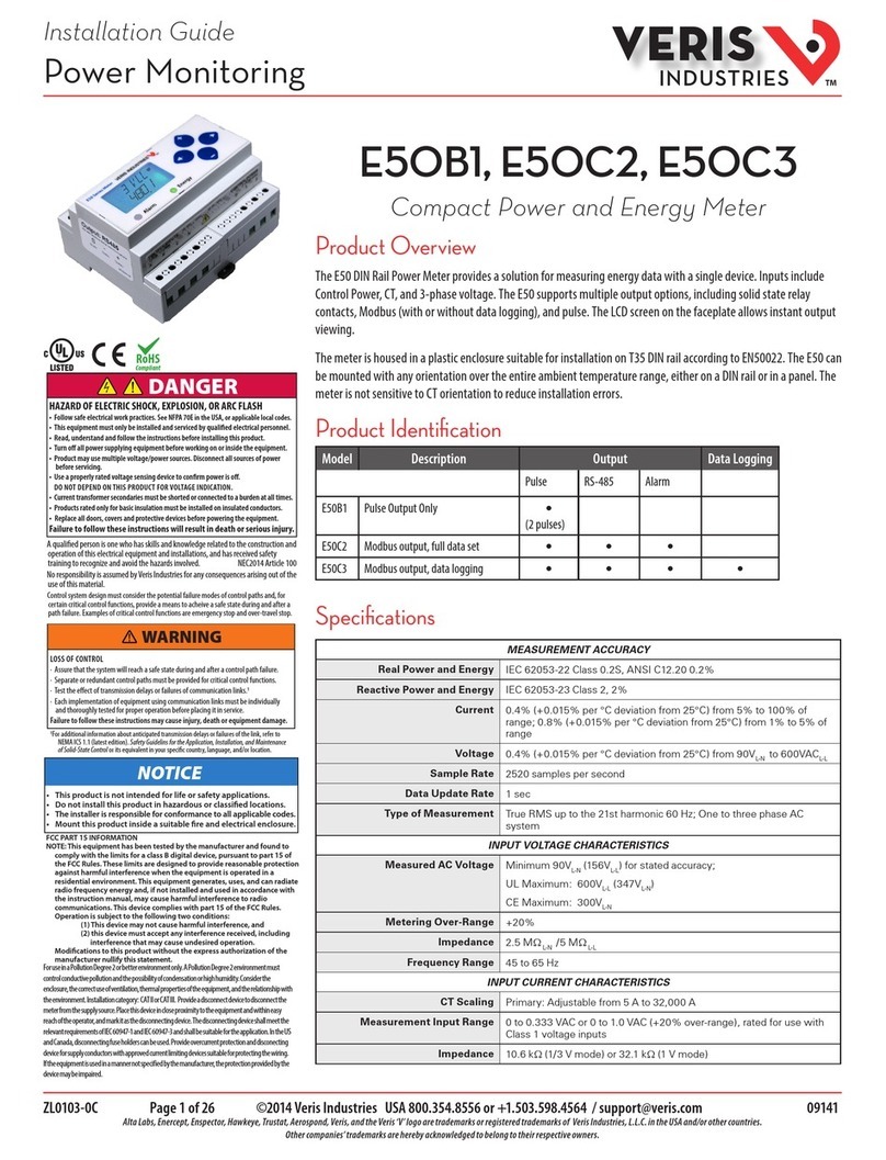
  9. Veris E51C2 User manual

Veris E51C2 User manual

ZL0067-0E Page 1 of 34 ©2018 Veris Industries USA 800.354.8556 or +1.503.598.4564 / suppor[email protected] 0818
Alta Labs, Enercept, Enspector, Hawkeye, Trustat, Aerospond, Veris, and the Veris ‘V’ logo are trademarks or registered trademarks of Veris Industries, L.L.C. in the USA and/or other countries.
Other companies’ trademarks are hereby acknowledged to belong to their respective owners.
For use in a Pollution Degree 2 or better environment only. A Pollution Degree 2
environment must control conductive pollution and the possibility of condensation or
high humidity. Consider the enclosure, the correct use of ventilation, thermal properties
of the equipment, and the relationship with the environment. Installation category:
CAT II or CAT III. Provide a disconnect device to disconnect the meter from the supply
source. Place this device in close proximity to the equipment and within easy reach of
the operator, and mark it as the disconnecting device. The disconnecting device shall
meet the relevant requirements of IEC 60947-1 and IEC 60947-3 and shall be suitable for
the application. In the US and Canada, disconnecting fuse holders can be used. Provide
overcurrent protection and disconecting device for supply conductors with approved
current limiting devices suitable for protecting the wiring. If the equipment is used in a
manner not specied by the manufacturer, the protection provided by the device may
be impaired.
HAZARD OF ELECTRIC SHOCK, EXPLOSION, OR ARC FLASH
• Follow safe electrical work practices. See NFPA 70E in the USA, or applicable local codes.
• This equipment must only be installed and serviced by qualified electrical personnel.
• Read, understand and follow the instructions before installing this product.
• Turn off all power supplying equipment before working on or inside the equipment.
• Any covers that may be displaced during the installation must be reinstalled
before powering the unit.
• Use a properly rated voltage sensing device to confirm power is off.
DO NOT DEPEND ON THIS PRODUCT FOR VOLTAGE INDICATION
Failure to follow these instructions will result in death or serious injury.
A qualied person is one who has skills and knowledge related to the construction and
operation of this electrical equipment and the installation, and has received safety
training to recognize and avoid the hazards involved. NEC Article 100
No responsibility is assumed byVeris Industries for any consequences arising out of the
use of this material.
DANGER
NOTICE
• This product is not intended for life or safety applications.
• Do not install this product in hazardous or classied locations.
• The installer is responsible for conformance to all applicable codes.
• Mount this product inside a suitable re and electrical enclosure.
FCC PART 15 INFORMATION
NOTE: This equipment has been tested by the manufacturer and found to
comply with the limits for a class B digital device, pursuant to part 15 of
the FCC Rules. These limits are designed to provide reasonable protection
against harmful interference when the equipment is operated in a
residential environment. This equipment generates, uses, and can radiate
radio frequency energy and, if not installed and used in accordance with
the instruction manual, may cause harmful interference to radio
communications. This device complies with part 15 of the FCC Rules.
Operation is subject to the following two conditions:
(1) This device may not cause harmful interference, and
(2) this device must accept any interference received, including
interference that may cause undesired operation.
Modifications to this product without the express authorization of the
manufacturer nullify this statement.
WARNING
LOSS OF CONTROL
∙ Assure that the system will reach a safe state during and after a control path failure.
∙ Separate or redundant control paths must be provided for critical control functions.
∙ Test the eect of transmission delays or failures of communication links.1
∙ Each implementation of equipment using communication links must be individually
and thoroughly tested for proper operation before placing it in service.
Failure to follow these instructions may cause injury, death or equipment damage.
1For additional information about anticipated transmission delays or failures of the link, refer to
NEMA ICS 1.1 (latest edition). Safety Guidelines for the Application, Installation, and Maintenance
of Solid-State Control or its equivalent in your specic country, language, and/or location.
Control system design must consider the potential failure modes of control paths and, for
certain critical control functions, provide a means to acheive a safe state during and after a
path failure. Examples of critical control functions are emergency stop and over-travel stop.
TM
Installation Guide
Power Monitoring
The safety of any system incorporating this equipment is the responsibility of the
assembler of the system.
Product Overview
The E51 DIN Rail Power Meter provides a solution for measuring energy data with a single device. Inputs include
Control Power, CTs, and 3-phase voltage. The E51 supports multiple output options, including solid state relay
contacts, Modbus (with or without data logging), and pulse. The LCD screen on the faceplate allows instant output
viewing.
The E51 meter is capable of bidirectional metering. Power is monitored in both directions (upstream and
downstream from the meter). The meter is housed in a plastic enclosure suitable for installation on T35 DIN rail
according to EN 50022. The E51 can be mounted either on a DIN rail or in a panel. Observe correct CT orientation
when installing the device.
E51C2, E51C3
Compact Bi-Directional
Power and Energy Meter
Specications
MEASUREMENT ACCURACY
Real Power and Energy IEC 62053-22 Class 0.2S, ANSI C12.20 0.2%
Reactive Power and Energy IEC 62053-23 Class 2, 2%
Current 0.2% (+0.005% per °C deviation from 25 °C) from 1% to 5% of range;
0.1% (+0.005% per °C deviation from 25 °C) from 5% to 100% of range
Voltage 0.1% (+0.005% per °C deviation from 25 °C) from 90 VacL- N to 600 VacL- L
Sample Rate 2520 samples per second; no blind time
Data Update Rate 1 sec.
Type of Measurement True RMS; one to three phase AC system
INPUT VOLTAGE CHARACTERISTICS
Measured AC Voltage Minimum 90 VL-N (156 VL-L ) for stated accuracy;
UL Maximums: 600 VL-L (347 VL- N); CE Maximum: 300 VL-N
Metering Over-Range +20%
Impedance 2.5 MΩL- N /5 MΩL-L
Frequency Range 45 to 65 Hz
INPUT CURRENT CHARACTERISTICS
CT Scaling Primary: Adjustable from 5 A to 32,000 A
Measurement Input Range 0 to 0.333 Vac or 0 to 1.0 Vac (+20% over-range), rated for use with Class 1
voltage inputs
Impedance 10.6 kΩ (1/3 V mode) or 32.1 kΩ (1 V mode)
Product Identication
Model Description Output Data Logging
Pulse RS-485 Alarm
E51C2 Modbus output, full data set • • •
E51C3 Modbus output, data logging • • • •
ZL0067-0E Page 2 of 34 ©2018 Veris Industries USA 800.354.8556 or +1.503.598.4564 / suppor[email protected] 0818
Alta Labs, Enercept, Enspector, Hawkeye, Trustat, Aerospond, Veris, and the Veris ‘V’ logo are trademarks or registered trademarks of Veris Industries, L.L.C. in the USA and/or other countries.
Other companies’ trademarks are hereby acknowledged to belong to their respective owners.
TM
E51C2, E51C3 Installation Guide
CONTROL POWER
AC 5 VA max.; 90V min.;
UL Maximums: 600 VL-L (347 VL- N); CE Maximum: 300 VL-N
DC* 3 W max.; UL and CE: 125 to 300 VDC
Ride Through Time 100 msec at 120 Vac
OUTPUT
Alarm Contacts N.C., static output (30Vac/dc, 100mA max. @ 25 °C,
derate 0.56 mA per °C above 25 °C)
Real Energy Pulse Contacts N.O., static output (30 Vac/dc, 100 mA max. @ 25°C,
derate 0.56 mA per °C above 25 °C)
RS-485 Port 2-wire, 1200 to 38400 baud, Modbus RTU
MECHANICAL CHARACTERISTICS
Weight 0.62 lb (0.28 kg)
IP Degree of Protection
(IEC 60529)
IP40 front display; IP20 meter
Display Characteristics Back-lit blue LCD
Terminal Block Screw Torque 0.37 to 0.44 ft-lb (0.5 to 0.6 N·m)
Terminal Block Wire Size 24 to 14 AWG (0.2 to 2.1 mm2)
Rail T35 (35mm) DIN Rail per EN 50022
OPERATING CONDITIONS
Operating Temperature Range -30° to 70 °C (-22° to 158 °F)
Storage Temperature Range -40° to 85 °C (-40° to 185 °F)
Humidity Range <95% RH non-condensing
Altitude of Operation 3000 m
Mounting Location Not suitable for wet locations. For indoor use only.
COMPLIANCE INFORMATION
US and Canada CAT III, Pollution Degree 2;
for distribution systems up to 347VL-N /600VacL-L
CE CAT III, Pollution Degree 2;
for distribution systems up to 300VL-N
Dielectric Withstand Per UL 508, IEC/EN 61010-1
Conducted and Radiated
Emissions
FCC part 15 Class B, EN 55011/EN 61000 Class B (residential and light industrial)
Conducted and Radiated
Immunity
EN 61000 Class A (heavy industrial)
US and Canada (cULus) UL 508 (open type device)/CSA 22.2 No. 14-05
Europe (CE) IEC/EN 61010-1
* External DC current limiting is required, see fuse recommendations.
Specications (cont.)
This meter implements the draft SunSpec 1.0 common elements starting at base 1 address 40001, and the proposed SunSpec 1.1
meter model at 40070 (these addresses are not in Modicon notation). See www.veris.com or www.sunspec.org for copies of these
specications.
The SunSpec Alliance logo is a trademark or registered trademark of the SunSpec Alliance.
SunSpec Alliance
Interoperability
Specication
Compliance
ZL0067-0E Page 3 of 34 ©2018 Veris Industries USA 800.354.8556 or +1.503.598.4564 / suppor[email protected] 0818
Alta Labs, Enercept, Enspector, Hawkeye, Trustat, Aerospond, Veris, and the Veris ‘V’ logo are trademarks or registered trademarks of Veris Industries, L.L.C. in the USA and/or other countries.
Other companies’ trademarks are hereby acknowledged to belong to their respective owners.
TM
E51C2, E51C3 Installation Guide
Table of Contents Dimensions 4
Application Example 4
Data Outputs 5
Product Diagram 5
Display Screen Diagram 5
Installation 6
Supported System Types 7
Wiring Symbols 7
Wiring 8
Control Power Diagrams 9
Quick Setup Instructions 10
Solid State Pulse Output 11
User Interface Menu Abbreviations Dened 11
User Interface for Data Conguration 12
Alert/Reset Information 13
User Interface for Setup 15
RS-485 Communications 17
Data Logging (E51C3 Only) 17
Modbus Point Map Overview 18
Standard Modbus Default Settings 19
Modbus Point Map 20
SunSpec Register Blocks 30
Troubleshooting 34
China RoHS Compliance Information (EFUP Table) 34
ZL0067-0E Page 4 of 34 ©2018 Veris Industries USA 800.354.8556 or +1.503.598.4564 / suppor[email protected] 0818
Alta Labs, Enercept, Enspector, Hawkeye, Trustat, Aerospond, Veris, and the Veris ‘V’ logo are trademarks or registered trademarks of Veris Industries, L.L.C. in the USA and/or other countries.
Other companies’ trademarks are hereby acknowledged to belong to their respective owners.
TM
E51C2, E51C3 Installation Guide
Dimensions
4.2”
(107mm)
3.6”
(91mm)
1.5”
(39mm)
2.3”
(59mm)
1.9”
(48mm)
1.8”
(45mm)
3.6“
(91 mm)
4.2“
(107 mm)
0.2“
(4 mm)
3.9“
(99 mm)
2.4“
(61 mm)
++
+
4.3“
(109 mm)
1.2“
(31 mm) 0.3“
(8 mm)
0.4“
(10 mm)
Bottom View (DIN Mount Option) Bottom View (Screw Mount Option)
Main Utility Grid Solar Panels
Imported Power
Exported Power
Application Example
ZL0067-0E Page 5 of 34 ©2018 Veris Industries USA 800.354.8556 or +1.503.598.4564 / suppor[email protected] 0818
Alta Labs, Enercept, Enspector, Hawkeye, Trustat, Aerospond, Veris, and the Veris ‘V’ logo are trademarks or registered trademarks of Veris Industries, L.L.C. in the USA and/or other countries.
Other companies’ trademarks are hereby acknowledged to belong to their respective owners.
TM
E51C2, E51C3 Installation Guide
Signed Power: Real, Reactive, and Apparent 3-phase total and per phase
Real and Apparent Energy Accumulators: Import, Export, and Net; 3-phase total and per phase
Reactive Energy Accumulators by Quadrant: 3-phase totals and per phase
Congurable for CT & PT ratios, system type, and passwords
Diagnostic alerts
Current: 3-phase average and per phase
Volts: 3-phase average and per phase Line-Line and Line-Neutral
Power Factor: 3-phase average and per phase
Frequency
Power Demand: Most Recent and Peak (Import and Export)
Demand Conguration: Fixed, Rolling Block, and External Sync (Modbus only)
Data Logging (E51C3 only)
Real Time Clock: user congurable
10 user congurable log buers: each buer holds 5760 16-bit entries
(User congures which 10 data points are stored in these buers)
User congurable logging interval
(When congured for a 15 minute interval, each buer holds 60 days of data)
Continuous and Single Shot logging modes: user selectable
Auto write pause: read logs without disabling the meter’s data logging mode
Data Outputs
Product Diagram
Alarm Energy


Two 5-character rows
of display text.
Top row alphanumeric;
Bottom row numeric only
The red Alarm LED lights when
any of the 3 phase voltages
drop below the selected thresh-
old. The green Energy LED lights
momentarily each time the
Energy output pulse is active.
CONTROL POWER
0.1A 50/60 Hz
A B C N 1 2
Alarm Energy
NC NO + - S
OUTPUT
Phase Loss
Alarm
Pulse
Modbus
Shield
VA
VB
VC
Neutral
Earth
Control
Power
UL: 90V L-N - 600V L-L CE: 90V L- N - 300V L-N
VOLTAGE INPUTS
CAT III 50/60 Hz
+
–
(X2) A(X1) (X2) B(X1) (X2) C(X1)
IA
IB
IC
X2 X1 X2 X1 X2 X1
CT Inputs 1 or 0.333 VAC
LCD Screen: Buttons:
+
–
(Up)
Select
(Right)
Next
(Down)
Select
(Left)
Back

 Tx
Rx
ERR
♥
Screen Name or Units
Diagnostic Alert
Logo
Numeric Data
Alive Indicator
Transmit Data
Receive Data
Receive Data Error


Export
Import
Display Screen
Diagram
ZL0067-0E Page 6 of 34 ©2018 Veris Industries USA 800.354.8556 or +1.503.598.4564 / suppor[email protected] 0818
Alta Labs, Enercept, Enspector, Hawkeye, Trustat, Aerospond, Veris, and the Veris ‘V’ logo are trademarks or registered trademarks of Veris Industries, L.L.C. in the USA and/or other countries.
Other companies’ trademarks are hereby acknowledged to belong to their respective owners.
TM
E51C2, E51C3 Installation Guide
Installation Disconnect power prior to installation.
Reinstall any covers that are displaced during the installation before powering the unit.
Mount the meter in an appropriate electrical enclosure near equipment to be monitored.
Do not install on the load side of a Variable Frequency Drive (VFD), aka Variable Speed Drive (VSD)
or Adjustable Frequency Drive (AFD).
Observe correct CT orientation.
The meter can be mounted in two ways: on standard 35 mm DIN rail or screw-mounted to the interior surface of the enclosure.
A. DIN Rail Mounting
1. Attach the mounting clips to the underside of the housing by sliding them into the slots from the inside. The stopping pegs
must face the housing, and the outside edge of the clip must be ush with the outside edge of the housing.
2. Snap the clips onto the DIN rail. See the diagram of the underside of the housing (below).
Clip flush with
outside edge
Snap onto
DIN rail
Insert clips from inside
3. To reduce horizontal shifting across the DIN rail, use two Veris AV02 end stop clips.
B. Screw Mounting
1. Attach the mounting clips to the underside of the housing by sliding them into the slots from the outside. The stopping pegs
must face the housing, and the screw hole must be exposed on the outside of the housing.
2. Use three #8 screws (not supplied) to mount the meter to the inside of the enclosure. See the diagram of the underside of the
housing (below).
Screw holes
exposed for
mounting
Insert clips from outside
ZL0067-0E Page 7 of 34 ©2018 Veris Industries USA 800.354.8556 or +1.503.598.4564 / suppor[email protected] 0818
Alta Labs, Enercept, Enspector, Hawkeye, Trustat, Aerospond, Veris, and the Veris ‘V’ logo are trademarks or registered trademarks of Veris Industries, L.L.C. in the USA and/or other countries.
Other companies’ trademarks are hereby acknowledged to belong to their respective owners.
TM
E51C2, E51C3 Installation Guide
Supported System
Types
The meter has a number of dierent possible system wiring congurations (see Wiring Diagrams section). To congure the meter,
set the System Type via the User Interface or Modbus register 130 (if so equipped). The System Type tells the meter which of its
current and voltage inputs are valid, which are to be ignored, and if neutral is connected. Setting the correct System Type prevents
unwanted energy accumulation on unused inputs, selects the formula to calculate the Theoretical Maximum System Power,
and determines which phase loss algorithm is to be used. The phase loss algorithm is congured as a percent of the Line-to-Line
System Voltage (except when in System Type 10) and also calculates the expected Line to Neutral voltages for system types that
have Neutral (12 & 40).
Values that are not valid in a particular System Type will display as “----” on the User Interface or as QNAN in the Modbus registers.
CTs Voltage Connections System Type Phase Loss Measurements Wiring
Diagram
Number
of wires
Qty ID Qty ID Type Modbus
Register 130
User Interface:
SETUP>S SYS
VLL VLN Balance Diagram
number
Single-Phase Wiring
2 1 A 2 A, N L-N 10 1L + 1n AN 1
2 1 A 2 A, B L-L 11 2L AB 2
3 2 A, B 3 A, B, N L-L with N 12 2L + 1n AB AN, BN AN-BN 3
Three-Phase Wiring
3 3 A, B, C 3 A, B, C Delta 31 3L AB, BC, CA AB-BC-CA 4
4 3 A, B, C 4 A, B, C, N Grounded
Wye
40 3L + 1n AB, BC, CA AN, BN, CN AN-BN-CN &
AB-BC-CA
5, 6
To avoid distortion, use parallel wires for control power and voltage inputs.
The following symbols are used in the wiring diagrams on the following pages.
Symbol Description
Voltage Disconnect Switch
Fuse (installer is responsible for ensuring compliance with local requirements. No
fuses are included with the meter.)
Earth ground
X2
X1 Current Transducer
Potential Transformer
Protection containing a voltage disconnect switch with a fuse or disconnect circuit
breaker. The protection device must be rated for the available short-circuit current at
the connection point.
CAUTION
RISK OF EQUIPMENT DAMAGE
• This product is designed only for use with 1V or 0.33V current
transducers (CTs).
• DO NOT USE CURRENT OUTPUT (e.g. 5A) CTs ON THIS PRODUCT.
• Failure to follow these instructions can result in overheating and
permanent equipment damage.
Wiring Symbols
ZL0067-0E Page 8 of 34 ©2018 Veris Industries USA 800.354.8556 or +1.503.598.4564 / suppor[email protected] 0818
Alta Labs, Enercept, Enspector, Hawkeye, Trustat, Aerospond, Veris, and the Veris ‘V’ logo are trademarks or registered trademarks of Veris Industries, L.L.C. in the USA and/or other countries.
Other companies’ trademarks are hereby acknowledged to belong to their respective owners.
TM
E51C2, E51C3 Installation Guide
RISK OF ELECTRIC SHOCK OR PERMANENT EQUIPMENT DAMAGE
CT terminals are referenced to the meter’s neutral and may be at elevated voltages:
· Do not contact meter terminals while the unit is connected
· Do not connect or short other circuits to the CT terminals
Failure to follow these instructions may cause injury, death or equipment damage.
WARNING
Wiring
Observe correct CT orientation.
N L1
X2
X1 White
Black
A
B
C
N
X1
X2
X1
X2
X1
X2
A
B
C
Diagram 1: 1-Phase Line-to-Neutral 2- Wire
System 1 CT
Diagram 2: 1-Phase Line-to-Line 2-Wire
System 1 CT
L1 L2
X2
X1
X2
X1
A
B
C
N
A
B
C
N
White
Black
White
Black
X1
X2
X1
X2
X1
X2
L1 L2
X2
X1
A
B
C
N
A
B
C
White
Black X1
X2
X1
X2
X1
X2
Diagram 3: 1-Phase Direct Voltage Connection 2 CT
L1 L2 L3
X2
X1
A
B
C
N
A
B
C
X2
X1
X2
X1
White
Black
White
Black
White
Black
X1
X2
X1
X2
X1
X2
Diagram 4: 3-Phase 3-Wire 3 CT no PT
Use System Type 11 (2L)
Use System Type 12 (2L + 1n) Use System Type 31 (3L)
Use System Type 10 (1L + 1n)
L1N L2 L3
X2
X1
A
B
C
N
A
B
C
X2
X1
X2
X1
White
Black
White
Black
White
Black
X1
X2
X1
X2
X1
X2
Diagram 5: 3-Phase 4-Wire Wye Direct Voltage Input
Connection 3 CT
Use System Type 40 (3L + 1n)
White
Black
White
Black
White
Black
L1N L2 L3
X2
X1
A
B
C
N
A
B
C
X2
X1
X2
X1
X1
X2
X1
X2
X1
X2
Diagram 6: 3-Phase 4-Wire Wye Connection 3 CT
3 PT
Use System Type 40 (3L + 1n)
ZL0067-0E Page 9 of 34 ©2018 Veris Industries USA 800.354.8556 or +1.503.598.4564 / suppor[email protected] 0818
Alta Labs, Enercept, Enspector, Hawkeye, Trustat, Aerospond, Veris, and the Veris ‘V’ logo are trademarks or registered trademarks of Veris Industries, L.L.C. in the USA and/or other countries.
Other companies’ trademarks are hereby acknowledged to belong to their respective owners.
TM
E51C2, E51C3 Installation Guide
Control Power
Direct Connect Control Power (DC Control Power)
L1N L2 L3 1 2G
L1N L2 L3
1 2G
L1
1 2G
L2 L3
Direct Connect Control Power (Line to Neutral)
Line to Neutral from 90 VAC to 347 VAC (UL) or 300 VAC (CE)
1 2G
Control Power Transformer (CPT) Connection
Direct Connect Control Power (Line to Line)
Line to Line from 90 VAC to 600 VAC (UL). In UL installations the
lines may be oating (such as a delta). If any lines are tied to an
earth (such as a corner grounded delta), see the Line to Neutral
installation limits. In CE compliant installations, the lines must
be neutral (earth) referenced at less than 300 VACL-N
The Control Power Transformer may be wired L-N or L-L. Output to
meet meter input requirements
DC Control Power from 125 VDC to 300 VDC
(UL and CE max.)
Fuse Recommendations
Keep the fuses close to the power source (obey local and national code requirements).
For selecting fuses and circuit breakers, use the following criteria:
• Select current interrupt capacity based on the installation category and fault current capability.
• Select over-current protection with a time delay.
• Select a voltage rating sucient for the input voltage applied.
• Provide overcurrent protection and disconnecting means to protect the wiring. For AC installations, use Veris AH02,
AH03, AH04, or equivalent. For DC installations, provide external circuit protection. Suggested: 0.5 A, time delay fuses.
• The earth connection (G) is required for electromagnetic compatibility (EMC) and is not a protective earth ground.
ZL0067-0E Page 10 of 34 ©2018 Veris Industries USA 800.354.8556 or +1.503.598.4564 / suppor[email protected] 0818
Alta Labs, Enercept, Enspector, Hawkeye, Trustat, Aerospond, Veris, and the Veris ‘V’ logo are trademarks or registered trademarks of Veris Industries, L.L.C. in the USA and/or other countries.
Other companies’ trademarks are hereby acknowledged to belong to their respective owners.
TM
E51C2, E51C3 Installation Guide
These instructions assume the meter is set to factory defaults. If it has been previously congured, check all optional values.
1. Press the +
+or
–
button repeatedly until SETUP screen appears.
2. to the PASWD screen.
3. through the digits. Use the +
+or
–
buttons to select the password (the default is 00000). Exit the screen to the right.
4. Use the +
+or
–
buttons to select the parameter to congure.
5. If the unit has an RS-485 interface, the rst Setup screen is S COM (set communications).
a. to the ADDR screen and through the address digits. Use the +
+or
–
buttons to select the Modbus address.
b. to the BAUD screen. Use the +
+or
–
buttons to select the baud rate.
c. to the PAR screen. Use the +
+or
–
buttons to select the parity.
d. back to the S COM screen.
6.
–
to the S CT (Set Current Transducer) screen. If this unit does not have an RS-485 port, this will be the rst screen.
a. to the CT V screen. Use the +
+or
–
buttons to select the voltage mode Current Transducer output voltage.
b. to the CT SZ screen and through the digits. Use the +
+or
–
buttons to select the CT size in amps.
c. back to the S CT screen.
7.
–
to the S SYS (Set System) screen.
a. to the SYSTM screen. Use the +
+or
–
buttons to select the System Type (see wiring diagrams).
b. back to the S SYS screen.
8. (Optional)
–
to the S PT (Set Potential Transformer) screen. If PTs are not used, then skip this step.
a. to the RATIO screen and through the digits. Use the +
+or
–
buttons to select the Potential Transformer step down
ratio.
b. back to the S PT screen.
9.
–
to the S V (Set System Voltage) screen.
a. to the VLL (or VLN if system is 1L-1n) screen and through the digits. Use the +
+or
–
buttons to select the Line to Line
System Voltage.
b. back to the S V screen.
10. Use the to exit the setup screen and then SETUP.
11. Check that the wrench is not displayed on the LCD.
a. If the wrench is displayed, use the +
+or
–
buttons to nd the ALERT screen.
b. through the screens to see which alert is on.
For the full setup instructions, see the conguration instructions on the following pages.
Quick Setup
Instructions
ZL0067-0E Page 11 of 34 ©2018 Veris Industries USA 800.354.8556 or +1.503.598.4564 / suppor[email protected] 0818
Alta Labs, Enercept, Enspector, Hawkeye, Trustat, Aerospond, Veris, and the Veris ‘V’ logo are trademarks or registered trademarks of Veris Industries, L.L.C. in the USA and/or other countries.
Other companies’ trademarks are hereby acknowledged to belong to their respective owners.
TM
E51C2, E51C3 Installation Guide
The meter has one normally open (N.O.) KZ Form
A output and one normally closed (N.C.) KY
solid-state output. One is dedicated to import
energy (Wh), and the other to Alarm.
The relay used for the Phase Loss contact is N.C.,
with closure indicating the presence of an alarm;
either loss of phase if the meter is powered, or
loss of power if the meter is not. The contacts are
open when the meter is powered and no phase
loss alarm conditions are present.
The solid state pulse outputs are rated for 30
VAC/DC nom.
Maximum load current is 100 mA at 25°C. Derate
0.56 mA per °C above 25°C.
See the Setup section for conguration
information.
Solid-State
Pulse Output
~
=
≤ 100 mA
~
=
≤ 100 mA
Alarm Energy Output
+ – S
Power Source**
3-30 VDC
6-30 VAC
Power Source**
3-30 VDC
6-30 VAC
Over-Current Protective
Device* (not supplied)
* The over-current protective device must be rated for the short circuit current at the
connection point.
** All pulse outputs and communication circuits are only intended to be connected to
non-hazardous circuits (SELV or Class 2). Do not connect to hazardous voltages.
Main Menu
IEC IEEE Description
D D Demand
MAX M Maximum Demand
P W Present Real Power
QVAR Present Reactive Power
SVA Present Apparent Power
A A Amps
UAB, UBC, UAC VAB, VBC, VAC Voltage Line to Line
V VLN Voltage Line to Neutral
PF PF Power Factor
U VLL Voltage Line to Line
HZ HZ Frequency
KSh KVAh Accumulated Apparent
Energy
KQh KVARh Accumulated Reactive
Energy
KPh KWh Accumulated Real Energy
PLOSS PLOSS Phase Loss
LOWPF LOWPF Low Power Factor Error
F ERR F ERR Frequency Error
I OVR I OVR Over Current
V OVR V OVR Over Voltage
Main Menu
IEC IEEE Description
PULSE PULSE kWh Pulse Output Overrun
(conguration error)
_PHASE _PHASE Summary Data for 1, 2, or 3
active phases
ALERT ALERT Diagnostic Alert Status
INFO INFO Unit Information
MODEL MODEL Model Number
OS OS Operating System
RS RS Reset System
SN SN Serial Number
RESET RESET Reset Data
PASWD PASWD Enter Reset or Setup
Password
ENERG ENERG Reset Energy Accumulators
DEMND DEMND Reset Demand Maximums
Import
Export
PULS_ PULS_ Pulse Counter (if equipped)
Q_ Q_ Quadrant 1-4 per IEEE 1459
n n Net
User Interface (UI)
Menu Abbreviations
Dened
The user can set the display mode to either IEC or IEEE notation in the SETUP menu.
ZL0067-0E Page 12 of 34 ©2018 Veris Industries USA 800.354.8556 or +1.503.598.4564 / suppor[email protected] 0818
Alta Labs, Enercept, Enspector, Hawkeye, Trustat, Aerospond, Veris, and the Veris ‘V’ logo are trademarks or registered trademarks of Veris Industries, L.L.C. in the USA and/or other countries.
Other companies’ trademarks are hereby acknowledged to belong to their respective owners.
TM
E51C2, E51C3 Installation Guide
User Interface
_PHAS
APHAS
BPHAS
CPHAS
3 A 3 VLL 3 VLN 3 KW
A A A VABA KW
1
, 2, or
3 Phase
Su
mmary Da
ta
Phase A:
All Systems
Phase B:
2 & 3 Phase
Systems Only
Phase C:
3 Phase
Systems Only
A VLN
Volts Line-Line (U)
(Average of Active
Phases)
APHAS
Amps (A)
(Average of
Active Phases)
Volts Line-Neutral (V)
(Average of Active
Phases)
Total Real
Power (P)
Power Factor
(Average of
Active Phases)
3 KVA
Total Apparent
Power (S)
B A B VBCB KWB VLN
BPHAS
C A C VACC KW
C VLN
CPHAS
A KVA
B KVA
C KVA
A PF
3 PF
B PF
C PF
3KVAR
Total Reactive
Power (Q)
AKVAR
BKVAR
CKVAR
DEMND D KW
Present
Real Power
Demand (P)
M KW MKVARM KVA
Maximum Apparent
Power (S)
Export Demand
Maximum Reactive
Power (Q)
Export Demand
Maximum Real
Power (P)
Export Demand
DKVAR
Present
Reactive Power
Demand (Q)
D KVA
Present
Apparent Power
Demand (S)
DEMND
Demand
>>> Scroll When Idle >>>
Total Import
Real Energy
A +KWh
3 +KWh
B +KWh
C +KWh
Total Export
Real Energy
A -KWh
3 -KWh
B -KWh
C -KWh
_PHAS
M KW MKVARM KVA
Maximum Apparent
Power (S)
Import Demand
Maximum Reactive
Power (Q)
Import Demand
Maximum Real
Power (P)
Import Demand
ENRGY
ENRGY
To:
SETUP
To:
ALERT
HZ
Frequency
Import
Real Energy
3 +KWh
Export
Real Energy
3 -KWh
Signed Net
Real Energy
3 KWh KVAR1
Quadrant 1
Import Reactive
Energy
KVAR2 KVAR3KVAR4KVAh
Signed Net
Apparent Energy
KVAh
Import
Apparent Energy
KVAh
Export
Apparent Energy
PULS1
Pulse Counter 1
(Import Wh)
PULS2
Pulse Counter 2
(Export Wh)
Energy
Accumulato
rs
and Counters Quadrant 2
Import Reactive
Energy
Quadrant 3
Export Reactive
Energy
Quadrant 4
Export Reactive
Energy See SETUP > SPULS > Wh/P
for Pulse Value
IEEE Display Mode
The units for all Power and Energy screens change to preserve resolution as the
accumulated totals increase. For example, energy starts out as Wh, then switches
to kWh, MWh, and eventually GWh as the accumulated value increases.
ZL0067-0E Page 13 of 34 ©2018 Veris Industries USA 800.354.8556 or +1.503.598.4564 / suppor[email protected] 0818
Alta Labs, Enercept, Enspector, Hawkeye, Trustat, Aerospond, Veris, and the Veris ‘V’ logo are trademarks or registered trademarks of Veris Industries, L.L.C. in the USA and/or other countries.
Other companies’ trademarks are hereby acknowledged to belong to their respective owners.
TM
E51C2, E51C3 Installation Guide
_PHAS
APHAS
BPHAS
CPHAS
3 A 3 U 3 V 3 KP
A A A U A KP
1, 2
, or 3 Ph
ase
Summ
ary Data
Phase A:
All Systems
Phase B:
2 & 3 Phase
Systems Only
Phase C:
3 Phase
Systems
Only
A V
Volts Line-Line (U)
(Average of Active
Phases)
APHAS
Amps (A)
(Average of
Active Phases)
Volts Line-Neutral (V)
(Average of Active
Phases)
Total Real
Power (P)
Power Factor
(Average of
Active Phases)
3 KS
Total Apparent
Power (S)
B A B U B KP
B V
BPHAS
C A C U C KPC V
CPHAS
A KS
B KS
C KS
A PF
3 PF
B PF
C PF
3 KQ
Total Reactive
Power (Q)
A KQ
B KQ
C KQ
DEMND D KP
Present
Real Power
Demand
M KP M KQ M KS
Maximum Apparent
Power (S)
Export Demand
Maximum Reactive
Power (Q)
Export Demand
Maximum Real
Power Export
Demand
D KQ
Present
Reactive Power
Demand
D KS
Present
Apparent Power
Demand
DEMND
Demand
>>> Scroll When Idle >>>
Total Import
Real Energy
A +KPh
3 +KPh
B +KPh
C +KPh
Total Export
Real Energy
A -KPh
3 -KPh
B -KPh
C -KPh
_PHAS
M KP M KQ M KS
Maximum Apparent
Power
Import Demand
Maximum Reactive
Power
Import Demand
Maximum Real
Power Import
Demand
ENRGY
ENRGY
To:
SETUP
To:
ALERT
HZ
Frequency
Import
Real Energy
E +KPh
Export
Real Energy
E -KPh
Signed Net
Real Energy
E KPhQ1 Qh
Quadrant 1
Import Reactive
Energy
Q2 Qh Q3 Qh Q4 Qh E KSh
Signed Net
Apparent Energy
E KSh
Import
Apparent Energy
E KSh
Export
Apparent Energy
PULS1
Pulse Counter 1
(Import Ph)
PULS2
Pulse Counter 2
(Export Ph)
Energy
Accumulators
and Counters Quadrant 2
Import Reactive
Energy
Quadrant 3
Export Reactive
Energy
Quadrant 4
Export Reactive
Energy See SETUP > SPULS > Wh/P
for Pulse Value
IEC Display Mode
Volts AB
Volts BC
Volts CA
The units for all Power and Energy screens change to preserve resolution as the
accumulated totals increase. For example, energy starts out as Wh, then switches
to kWh, MWh, and eventually GWh as the accumulated value increases.
User Interface
(cont.)
ZL0067-0E Page 14 of 34 ©2018 Veris Industries USA 800.354.8556 or +1.503.598.4564 / suppor[email protected] 0818
Alta Labs, Enercept, Enspector, Hawkeye, Trustat, Aerospond, Veris, and the Veris ‘V’ logo are trademarks or registered trademarks of Veris Industries, L.L.C. in the USA and/or other countries.
Other companies’ trademarks are hereby acknowledged to belong to their respective owners.
TM
E51C2, E51C3 Installation Guide
SETUP
ALERT
RESET
Back
Display “nOnE” if no alerts
To Setup
Setup
Meter
Reset
Data
Phase Loss
A B C
Low Power Factor
A B C
Frequency Out
of Range
A
Current
Out of Range
Voltage
Out of Range
A B C A B C
INFO MODEL OS SNRS
Serial
Number
Reset
System
Operating
System
ALERT
INFO
PLOSS
--------
A b C
LOWPF
--------
A b C
F ERR
--------
A
I OVR
--------
A b C
V OVR
--------
A b C
PASWD
--------
00000
PASWD
--------
00000
Model
Number
Energy Pulse Output:
Error = Overrun Error
ConF = Configuration Error
PULSE
--------
Error
ENERG
--------
rES
ResetEnergy
Accumulators to 0
Unit
Information
Alert Status
(check if
Wrench on
LCD)
RESET
Enter Reset
Password
Enter Setup
Password
To: ENRGY
To: DEMND
COUNT
--------
rES
Reset Pulse
Counters to 0
DEMND
--------
rES
Reset Demand
Maximums to Present
PASWD – Enter
the Reset Password
(configured in the setu
p menu).
ENERG – Reset all En
ergy
Accumulators (Wh, VAR
h, VAh) to 0.
Press “+” or “-“ to Reset.
DEMND – Reset all
Maximum
Demand (W
, VAR, VA) to the present
Demand. Hit “+” or “-“
to Reset.
COUNT – Reset the pu
lse counters.
Press “+” or “-“ to Reset.
Alert/Reset
Information
ZL0067-0E Page 15 of 34 ©2018 Veris Industries USA 800.354.8556 or +1.503.598.4564 / suppor[email protected] 0818
Alta Labs, Enercept, Enspector, Hawkeye, Trustat, Aerospond, Veris, and the Veris ‘V’ logo are trademarks or registered trademarks of Veris Industries, L.L.C. in the USA and/or other countries.
Other companies’ trademarks are hereby acknowledged to belong to their respective owners.
TM
E51C2, E51C3 Installation Guide
Next
Next
From:
SETUP > PASWD
ADDR
--------
001
BAUD
--------
38400
19200
9600
4800
2400
1200
PAR
--------
nOnE
EvEn
Odd
Set Communications Parameters:
ADDR - Modbus Address: 1 – 247.
+ increments the selected (blinking) digit.
-selects the digit to the left.
BAUD - Baud Rate: 1200 – 38400 Baud
PAR - Parity: Odd, Even, None
+or –to step through the options.
Set Current Transducer:
CT V - CT Input Voltage: + or –to Select 1.0 or .33V.
CT SZ - CT Size: in Amps. Maximum is 32000 Amps.
Set System Configuration:
SYSTM: + or –to step through the following System Type options:
System Reg 130 CTs Description
3L-1n 40 3 Wye Three Phase: A, B, & C with Neutral (Default).
3L 31 3 Delta Three Phase: A, B & C; no Neutral
2L-1n 12 2 Single Split Phase: A & B with Neutral
2L 11 1 Single Phase: A & B; no Neutral
1L-1n 10 1 Single Phase: A to Neutral
System
Type
Current
Transformer
S SYS
Next
S CT
CT V
--------
1.0
.33
CT SZ
--------
100
SYSTM
--------
3L-1n
3L
2L-1n
2L
1L-1n
Back To SETUP
Back
Back
Back S COM
To Setup p. 2 “SPLOS”
Next
S PT
Set Potential Transfomer Ratio:
RATIO – Potential transformer step down is RATIO:1. Default is 1:1
(No PT installed). See Install for wiring diagrams. This value must be
set before the System Voltage (if used).
Potential
Transformer
RATIO
--------
001.00
Back
S V
Back
Sytem
Voltage Next
Set System Voltage:
V LL – The nominal Line to Line Voltage for the system. This is used
by the meter to calculate the theoretical maximum system power, and
as the reference voltage for setting the Phase Loss threshold.
Maximum is 32000 Volts. For system type 1+N (10), this is a Line to
Neutral Voltage, indicated by “V LN”. Note: the meter will reject settings
that are not within the meter’s operating range when divided by the PT
ratio.
V LL
--------
00600
S PWR
Back
Sytem
Voltage
MX KW
--------
103.92
Next
System Power:
MX KW – The theoretical Maximum System Power is calculated by the
meter from the System Voltage, CT size, and System Type. Power
Factor is assumed to be unity. The value of System Power is used to
determine which combinations of pulse weight and duration are valid
and will keep up with the maximum power the meter will see. This value
is read only.
Note: Bold is the Default.
To Setup p. 2 “SPASS”
RS-485
Output
UI for Setup
ZL0067-0E Page 16 of 34 ©2018 Veris Industries USA 800.354.8556 or +1.503.598.4564 / suppor[email protected] 0818
Alta Labs, Enercept, Enspector, Hawkeye, Trustat, Aerospond, Veris, and the Veris ‘V’ logo are trademarks or registered trademarks of Veris Industries, L.L.C. in the USA and/or other countries.
Other companies’ trademarks are hereby acknowledged to belong to their respective owners.
TM
E51C2, E51C3 Installation Guide
Next
Set Passwords:
SETUP - The Password to enter the SETUP menu.
RESET - The Password to enter the RESET menu.
RESET
--------
00000
SPASS
Setup
Passwords
SETUP
--------
00000
Back
Next
SDMND
INTRV
--------
6
5
4
3
2
1
Demand
SEC
--------
00900
Back
Set Demand Interval:
INTRV - The number of Sub-Intervals (1 to 6) in a Demand Interval.
Default is 1 (block demand).
SEC - Sub-Interval length in seconds. Default is 900 (15 minutes).
Set to 0 for external sync-to-comms (Modbus units only).
Next
S DIS
Display
Units
UNITS
--------
IEEE
IEC
Back
Set Display Units: +/- to switch between:
IEEE – VLL VLN W VAR VA Units.
IEC - U V P Q S Units.
To Setup p. 1 “S PWR”
Max
PPS
--------
1
2
5
10
20
50
Pulse
Output
Next
Set Pulse:
The System Type , CT size, PT Ratio, and System Voltage must
all be configured before setting the Pulse Energy. If any of these
parameters are changed, the meter will hunt for a new Pulse
Duration, but will not change the Pulse Energy. If it cannot find a
solution, the meter will display the wrench, show “ConF” in the
ALARM -> PULSE screen, and enable Energy pulse output
configuration error bit in the Modbus Diagnostic Alert Bitmap (if
equipped).
Wh/P - Set Pulse Energy: In Watt Hours (& VAR Hours, if
present) per Pulse. When moving down to a smaller energy, the
meter will not allow the selection if it cannot find a pulse duration
that will allow the pulse output to keep up with Theoretical
Maximum System Power (see S_PWR screen). When moving
up to a larger energy, the meter will jump to the first value where
it can find a valid solution.
mS/P – Minimum Pulse Duration Time: This read only value
is set by the meter to the slowest duration (in mS per closure)
that will keep up with the Theoretical Maximum System Power.
The open time is greater than or equal to the closure time. The
maximum Pulses Per Second (PPS) is shown in yellow.
mS/P
--------
500
250
100
50
25
10
SPULS
Back
Wh/P
--------
10000
1000
100
10
SPLOS
Back
IMBAL
--------
0.25
Next
VOLTS
--------
0.10
Set Phase Loss:
VOLTS - Phase Loss Voltage: The fraction of the system
voltage below which Phase Loss Alarm is on. For system
types with neutral, the Line to Neutral voltage is also
calculated and tested. If the System Voltage is 600 and the
fraction is set to 0.10, then the Phase Loss threshold will be
60 volts.
IMBAL - Phase Loss Imbalance: The fractional difference
in Line to Line voltages above which Phase Loss Alarm is
on. For system types with neutral, the Line to Neutral
voltages are also tested. For system types 1+N (10) and 2
(11) , imbalance is not tested.
Phase
Loss
Back To SETUP
To Setup page 1 “S COM”
UI for Setup
(cont.)
ZL0067-0E Page 17 of 34 ©2018 Veris Industries USA 800.354.8556 or +1.503.598.4564 / suppor[email protected] 0818
Alta Labs, Enercept, Enspector, Hawkeye, Trustat, Aerospond, Veris, and the Veris ‘V’ logo are trademarks or registered trademarks of Veris Industries, L.L.C. in the USA and/or other countries.
Other companies’ trademarks are hereby acknowledged to belong to their respective owners.
TM
E51C2, E51C3 Installation Guide
Daisy-chaining Devices to the Power Meter
The RS-485 slave port allows the power meter to be connected in a daisy chain with up to 63 2-wire devices.
–
+
S
120 Ω terminator on the rst and last
device of the daisy chain
Shield wire
Notes
• The terminal’s voltage and current ratings are compliant with the requirements of the EIA RS-485 communications
standard.
• The RS-485 transceivers are ¼ unit load or less.
• RS-485+ has a 47 k pull up to +5V, and RS-485- has a 47 k pull down to Shield (RS-485 signal ground).
• Wire the RS-485 bus as a daisy chain from device to device, without any stubs. Use 120  termination resistors at each
end of the bus (not included).
• Shield is not internally connected to Earth Ground.
• Connect Shield to Earth Ground somewhere on the RS-485 bus.
For all terminals:
• When tightening terminals, apply the correct torque: 0.37 to 0.44
ft·lb (0.5-0.6 N·m).
• Use 14-24 gauge (2.1-0.2 mm2) wire.
RS-485
Communications
The E51C3 includes a data logging feature that records 10 meter parameters, each in its own buer.
Configuration
Use register 150 to set the data logging time subinterval. Writing to the storage buer is triggered by the subinterval timer. The
default subinterval is 15 minutes (at a 15 minute interval setting, the buers hold 60 days of data). An external timer can be used
over Modbus by setting this register to 0.
Use register 159 to turn on data logging and select either Single Shot or Continuous mode. (default is data logging on, Continuous
mode). In Single Shot mode, the meter records data until the buer is full. When the buer is full, the meter stops recording
new readings. Data for this time period is kept, but newer energy information is lost. In Continuous mode, the meter continues
to record energy data as long as the meter is operating. The buer can only hold 5760 entries at one time, however, so when the
number of records exceeds 5760, the oldest entry is deleted to make room for the newest.
Registers 169-178 contain the pointers to 10 data storage buers. Each buer is user-congurable with the Modbus address of the
16-bit data output to be stored. 32-bit data, such as oating point data or 32-bit integer energy accumulators, require two buers.
However, the lower 16 bits of an integer energy accumulator can be stored in a single buer (optional).
When the E51C3 is rst installed, the buers contain QNAN data, with a value of 0x8000. This data is considered invalid. If the
buer is reset at any point, all entries in the buers are overwritten with this 0x8000 value, indicating that it is invalid. All invalid
data is overwritten as the meter lls the buer with new data entries.
Reading Data
Use register 158 to choose which buer to read. When this register value is set to 0, the meter is in data logging mode. Changing
this value from 0 to (1 through 10)switches the meter to reading mode and selects a buer to read. Data from the selected buer
appears in registers 8000 to 13760.
Data Logging
(E51C3 only)
Red
Black
Gray
0.37 to 0.44 ft-lb
(0.5 to 0.6 N-m)
Use 14 to 24 gauge wire
ZL0067-0E Page 18 of 34 ©2018 Veris Industries USA 800.354.8556 or +1.503.598.4564 / suppor[email protected] 0818
Alta Labs, Enercept, Enspector, Hawkeye, Trustat, Aerospond, Veris, and the Veris ‘V’ logo are trademarks or registered trademarks of Veris Industries, L.L.C. in the USA and/or other countries.
Other companies’ trademarks are hereby acknowledged to belong to their respective owners.
TM
E51C2, E51C3 Installation Guide
Read/Write Collision
If the demand sub-interval timeout occurs while the user is reading a page (register 158 ≠ 0), the log data will be held in RAM
until the next demand subinterval. At that time, both the saved data from the previous cycle and the new data will be written to
the log, whether the page register has been set back to 0 or not. Error bits in the Log Status Register (160) track these conditions.
Subsequent log writes will proceed normally. Provided the log read is concluded in less time than the demand sub-interval, this
mechanism handles the occasional collision and prevents the user from reading data as the buer is being updated.
The Log Status Register has additional error ag bits that indicate whether logging has been reset or interrupted (power cycle,
etc.) during the previous demand sub-interval, and whether the Real-Time Clock has been changed (re-initialized to default date/
time due to a power-cycle or modied via Modbus commands).
The E51C2 Full Data Set (FDS) model features data outputs such as demand calculations, per phase signed watts VA and VAR,
import/export Wh and VAh, and VARh accumulators by quadrant. The E51C3 Data Logging model includes the FDS and adds log
conguration registers 155-178 and log buer reading at registers 8000-13760. The meter supports variable CTs and PTs, allowing
a much wider range of operation from 90V x 5A up to 32000V x 32000A. To promote this, the meter permits variable scaling of the
16-bit integer registers via the scale registers. The 32-bit oating point registers do not need to be scaled.
Integer registers begin at 001 (0x001). Floats at 257 (0x101). Conguration registers at 129 (0x081). Values not supported in a
particular System Type conguration report QNAN (0x8000 in Integer Registers, 0x7FC00000 in Floating Point Registers). Register
addresses are in PLC style base 1 notation. Subtract 1 from all addresses for the base 0 value used on the Modbus RS-485 link.
Supported Modbus Commands
Note: ID String information varies from model to model. Text shown here is an example.
Command Description
0x03 Read Holding Registers
0x04 Read Input Registers
0x06 Preset Single Register
0x10 Preset Multiple Registers
0x11
Report ID
Return string:
byte0: address
byte1: 0x11
byte2: #bytes following w/out crc
byte3: ID byte = 247
byte4: status = 0xFF if the operating system is used; status = 0x00 if the reset system is used
bytes5+: ID string =“Veris Industries E51xx Power Meter Full Data Set” or“Veris Industries E51xx Power Meter - RESET
SYSTEM RUNNING RSVersion x.xxx”last 2 bytes: CRC
0x2B
Read Device Identication, BASIC implementation (0x00, 0x01 and 0x02 data), Conformity Level 1.
Object values:
0x01:“Veris Industries”
0x02:“ E51xx”
0x03:“Vxx.yyy”, where xx.yyy is the OS version number (reformatted version of the Modbus register #7001, (Firmware
Version, Operating System).
If register #7001 == 12345, then the 0x03 data would be“V12.345”).
Legend
The following table lists the addresses assigned to each data point. For oating point format variables, each data point appears
twice because two 16-bit addresses are required to hold a 32-bit oat value. Negative signed integers are 2’s complement.
Modbus Point Map
Overview
Data Logging
(E51C3 only), cont.
ZL0067-0E Page 19 of 34 ©2018 Veris Industries USA 800.354.8556 or +1.503.598.4564 / suppor[email protected] 0818
Alta Labs, Enercept, Enspector, Hawkeye, Trustat, Aerospond, Veris, and the Veris ‘V’ logo are trademarks or registered trademarks of Veris Industries, L.L.C. in the USA and/or other countries.
Other companies’ trademarks are hereby acknowledged to belong to their respective owners.
TM
E51C2, E51C3 Installation Guide
R/W R=read only
R/W=read from either int or oat formats, write only to integer format.
NV Value is stored in non-volatile memory. The value will still be available if the meter experiences a power loss and reset.
Format
UInt Unsigned 16-bit integer.
SInt Signed 16-bit integer.
ULong Unsigned 32-bit integer; Upper 16-bits (MSR) in lowest-numbered / rst listed register (001/002 = MSR/LSR).
SLong Signed 32-bit integer; Upper 16-bits (MSR) in lowest-numbered / rst listed register (001/002 = MSR/LSR).
Float 32-bit oating point; Upper 16-bits (MSR) in lowest-numbered / rst listed register (257/258 = MSR/LSR). Encoding is
per IEEE standard 754 single precision.
Units Lists the physical units that a register holds.
Scale
Factor
Some Integer values must be multiplied by a constant scale factor (typically a fraction), to be read correctly.This is done to allow
integer numbers to represent fractional numbers.
Range Denes the limit of the values that a register can contain.
Standard Modbus
Default Settings
Setting Value Modbus
Register
Setup Password 00000 
Reset Password 00000 
System Type 40 (3 + N) Wye 130
CT Primary Ratio (if CTs are not included) 100A 131
CT Secondary Ratio 1V 132
PT Ratio 1:1 (none) 133
System Voltage 600 V L-L 134
Max. Theoretical Power
(Analog Output: full scale (20mA or 5V))
104 kW 135
Display Mode 1 (IEEE units) 137
Phase Loss 10% of SystemVoltage (60V), 25% Phase to Phase Imbalance 142, 143
Pulse Energy 1 (kWh/pulse) 144
Demand: number of sub-intervals per interval 1 (block mode) 149
Demand: sub-interval length 900 sec (15 min) 150
Modbus Address 001 
Modbus Baud Rate 19200 baud 
Modbus Parity None 
Log Read Page 0 158
Logging Conguration Register 0 159
Log Register Pointer 1 3 (Import Real Energy MSR) 169
Log Register Pointer 2 4 (Import Real Energy LSR) 170
Log Register Pointer 3 5 (Export Real Energy MSR) 171
Log Register Pointer 4 6 (Export Real Energy LSR) 172
Log Register Pointer 5 29 (Real Demand) 173
Log Register Pointer 6 30 (Reactive Demand) 174
Log Register Pointer 7 31 (Apparent Demand) 175
Log Register Pointer 8 155 (Month/Day) 176
Log Register Pointer 9 156 (Year/Hour) 177
Log Register Pointer 10 157 (Minutes/Seconds) 178
Modbus Point Map
Overview (cont.)
ZL0067-0E Page 20 of 34 ©2018 Veris Industries USA 800.354.8556 or +1.503.598.4564 / suppor[email protected] 0818
Alta Labs, Enercept, Enspector, Hawkeye, Trustat, Aerospond, Veris, and the Veris ‘V’ logo are trademarks or registered trademarks of Veris Industries, L.L.C. in the USA and/or other countries.
Other companies’ trademarks are hereby acknowledged to belong to their respective owners.
TM
E51C2, E51C3 Installation Guide
Modbus Point Map
E51C2 FDS
E51C3 Log
Register
R/W NV Format Units Scale Range Description
Integer Data: Summary of Active Phases
• • 001 R NV SLong kWh E-2147483647 to
+2147483647 Real Energy: Net (Import - Export) MSR
Accumulated
Real Energy
(Ph)
Clear via reset
register 129
• • 002 LSR
• • 003 R NV ULong kWh E 0 to 0xFFFFFFFF Real Energy: Quadrants 1 & 4
Import
MSR
• • 004 LSR
• • 005 R NV ULong kWh E 0 to 0xFFFFFFFF Real Energy: Quadrants 2 & 3
Export
MSR
• • 006 LSR
• • 007 R NV ULong kVARh E 0 to 0xFFFFFFFF Reactive Energy - Quadrant 1:
Lags Import Real Energy (IEC) Inductive (IEEE)
MSR
Accumulated
Reactive Energy
(Qh):
Quadrants 1 + 2
= Import
Quadrants 3 + 4
= Export
• • 008 LSR
• • 009 R NV ULong kVARh E 0 to 0xFFFFFFFF Reactive Energy - Quadrant 2:
Leads Export Real Energy (IEC) Inductive (IEEE)
MSR
• • 010 LSR
• • 011 R NV ULong kVARh E 0 to 0xFFFFFFFF Reactive Energy - Quadrant 3:
Lags Export Real Energy (IEC) Capacitive (IEEE)
MSR
• • 012 LSR
• • 013 R NV ULong kVARh E 0 to 0xFFFFFFFF Reactive Energy - Quadrant 4:
Leads Import Real Energy (IEC) Capacitive (IEEE)
MSR
• • 014 LSR
• • 015 R NV SLong kVAh E-2147483647 to
+2147483647 Apparent Energy: Net (Import - Export) MSR Accumulated
Apparent
Energy (Sh):
Import and
Export
correspond
with Real
Energy
• • 016 LSR
• • 017 R NV ULong kVAh E 0 to 0xFFFFFFFF Apparent: Quadrants 1 & 4
Import
MSR
• • 018 LSR
• • 019 R NV ULong kVAh E 0 to 0xFFFFFFFF Apparent: Quadrants 2 & 3
Export
MSR
• • 020 LSR
• • 021 R SInt kW W -32767 to +32767 Total Instantaneous Real (P) Power
• • 022 R SInt kVAR W 0 to 32767 Total Instantaneous Reactive (Q) Power
• • 023 R UInt kVA W 0 to 32767 Total Instantaneous Apparent (S) Power (vector sum)
• • 024 R SInt Ratio 0.0001 -10000 to +10000 Total Power Factor (total kW / total kVA)
• • 025 R UInt Volt V 0 to 32767 Voltage, L-L (U), average of active phases
• • 026 R UInt Volt V 0 to 32767 Voltage, L-N (V), average of active phases
• • 027 R UInt Amp I 0 to 32767 Current, average of active phases
• • 028 UInt Hz 0.01 4500 to 6500 Frequency
• • 029 R SInt kW W -32767 to +32767 Total Real Power Present Demand
• • 030 SInt kVAR W -32767 to +32767 Total Reactive Power Present Demand
• • 031 R SInt kVA W -32767 to +32767 Total Apparent Power Present Demand
• • 032 R NV SInt kW W -32767 to +32767 Total Real Power Max. Demand
Import
Reset via register
129
• • 033 R NV SInt kVAR W -32767 to +32767 Total Reactive Power Max. Demand
• • 034 R NV SInt kVA W -32767 to +32767 Total Apparent Power Max. Demand
• • 035 R NV SInt kW W -32767 to +32767 Total Real Power Max. Demand
Export• • 036 R NV SInt kVAR W -32767 to +32767 Total Reactive Power Max. Demand
• • 037 R NV SInt kVA W -32767 to +32767 Total Apparent Power Max. Demand
• • 038 R UInt Reserved, returns 0x8000 (QNAN)
• • 039 R NV ULong 0 to 0xFFFFFFFF Pulse Counter 1
(Import Real Energy)
MSR Contact Closure Counters.Valid for both pulse
inputs and outputs. E51Cx counts are shown in
(). See register 144 - Energy Per Pulse for the
Wh per pulse count.
• • 040 LSR
• • 041 R NV ULong 0 to 0xFFFFFFFF Pulse Counter 2
(Export Real Energy)
MSR
• • 042 LSR

This manual suits for next models

1

Other Veris Measuring Instrument manuals

Veris Enercept System Calibrated E20 Series User manual

Veris

Veris Enercept System Calibrated E20 Series User manual

Veris H681-V Series User manual

Veris

Veris H681-V Series User manual

Veris E61C20 User manual

Veris

Veris E61C20 User manual

Veris E50B1 User manual

Veris

Veris E50B1 User manual

Veris PX3 Series User manual

Veris

Veris PX3 Series User manual

Veris H8150-0100-0-1 User manual

Veris

Veris H8150-0100-0-1 User manual

Veris H81xx User manual

Veris

Veris H81xx User manual

Veris E30 series User manual

Veris

Veris E30 series User manual

Veris Enercept FLEX E20 Series User manual

Veris

Veris Enercept FLEX E20 Series User manual

Veris E30 series User manual

Veris

Veris E30 series User manual

Veris H704-42 User manual

Veris

Veris H704-42 User manual

Veris HW2 Series User manual

Veris

Veris HW2 Series User manual

Popular Measuring Instrument manuals by other brands

Stahl ConSig 8010 operating instructions

Stahl

Stahl ConSig 8010 operating instructions

LaserLine DigiLevel Compact manual

LaserLine

LaserLine DigiLevel Compact manual

Tecnogas HT-89 Operation manual

Tecnogas

Tecnogas HT-89 Operation manual

GSi 18 user manual

GSi

GSi 18 user manual

GW Instek GFC-8270H manual

GW Instek

GW Instek GFC-8270H manual

Elen NDA 100/3-2 TH Series user manual

Elen

Elen NDA 100/3-2 TH Series user manual

Katronic KATflow 210 operating instructions

Katronic

Katronic KATflow 210 operating instructions

Hanna Instruments HI96816 instruction manual

Hanna Instruments

Hanna Instruments HI96816 instruction manual

GMC-I Prosys CP 2005 operating instructions

GMC-I Prosys

GMC-I Prosys CP 2005 operating instructions

Foster + Freeman ECCO2 user manual

Foster + Freeman

Foster + Freeman ECCO2 user manual

Banner A-GAGE High-Resolution MINI-ARRAY MAHE6A instruction manual

Banner

Banner A-GAGE High-Resolution MINI-ARRAY MAHE6A instruction manual

Anritsu MS2830A Operation manual

Anritsu

Anritsu MS2830A Operation manual

Alcatel adixen ASD 2001 user manual

Alcatel

Alcatel adixen ASD 2001 user manual

Hioki 9605 instruction manual

Hioki

Hioki 9605 instruction manual

Alfano AStrO LVF A-165 user manual

Alfano

Alfano AStrO LVF A-165 user manual

HBK B&K 2245 user guide

HBK

HBK B&K 2245 user guide

Kimo CT 110 user manual

Kimo

Kimo CT 110 user manual

Autonics PSAN Series manual

Autonics

Autonics PSAN Series manual

manuals.online logo
manuals.online logoBrands
  • About & Mission
  • Contact us
  • Privacy Policy
  • Terms and Conditions

Copyright 2025 Manuals.Online. All Rights Reserved.