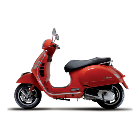
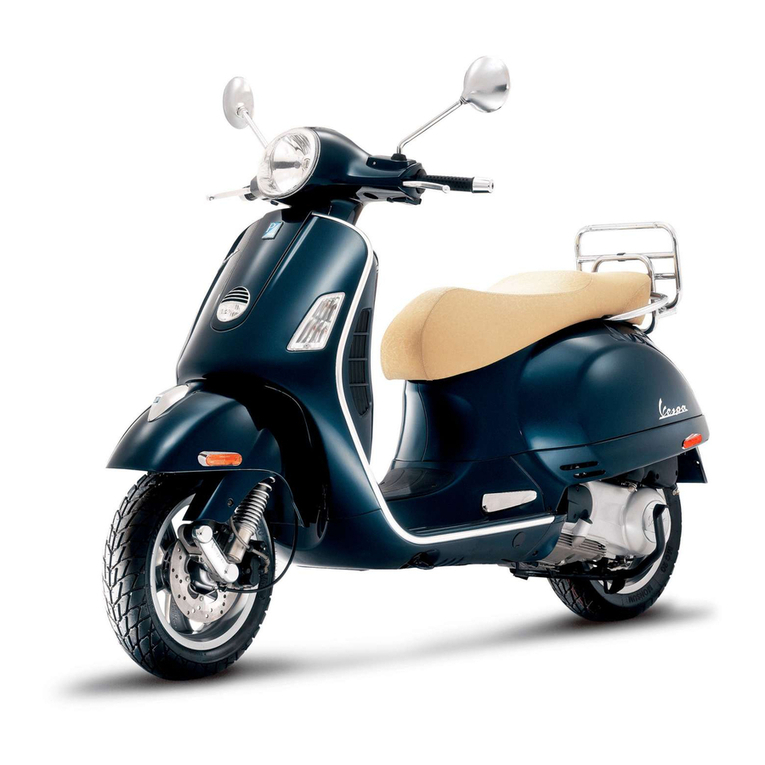
VESPA GTS 300 HPE User manual

Vespa would like to thank you
for choosing one of its products. We have prepared this manual to help you to get the very best from your vehicle. Please read it carefully before riding
the vehicle for the first time. It contains information, tips and precautions for using your vehicle It also describes features, details and devices to assure
you that you have made the right choice. We believe that if you follow our suggestions, you will soon get to know your new vehicle well and that it will
continue to give you satisfactory service for many years to come. This booklet forms an integral part of the vehicle; should the vehicle be sold, it must
be transferred to the new owner.
Vespa Gts 300 hpe
Ed. 02_10/2022 Cod. 1Q000963 (IT-FR-DE-ES-NL-EN -PT-EL)

The instructions given in this manual are intended to provide a clear, simple guide to using your vehicle; details are also given of routine maintenance
procedures and regular checks that should be carried out on the vehicle at an Authorised PIAGGIO Dealer or Service Centre. The booklet also
containsinstructionsforsimplerepairs.Anyoperationsnotspecificallydescribedinthisbookletrequiretheuseofspecialtoolsand/orparticulartechnical
knowledge: to carry out these operations refer to any authorised PIAGGIO Dealer or Service Centre.
2

Personal safety
Failure to completely observe these instructions will result in serious risk of personal
injury.
Safeguarding the environment
Sections marked with this symbol indicate the correct use of the vehicle to prevent dam-
aging the environment.
Vehicle intactness
The incomplete or non-observance of these regulations leads to the risk of serious
damage to the vehicle and sometimes even the invalidity of the guarantee.
The signs that you see on this page are very important. They are used to highlight parts
of the booklet that should be read with particular care. The different symbols are used
to make each topic in the manual simple and quick to locate.
3

4

INDEX
GENERAL RULES....................................................................... 7
General rules............................................................................ 8
VEHICLE...................................................................................... 9
Dashboard................................................................................ 10
Analogue instrument panel....................................................... 11
Indicator unit............................................................................. 15
Digital lcd display...................................................................... 17
*MODE* button...................................................................... 32
Starter switch............................................................................ 33
Locking the steering wheel.................................................... 34
Releasing the steering wheel................................................ 35
Switch direction indicators........................................................ 35
Horn button............................................................................... 36
Light switch............................................................................... 36
Start-up button.......................................................................... 37
Engine stop switch.................................................................... 38
System ABS.............................................................................. 38
System ASR.............................................................................. 40
The immobilizer system............................................................ 47
Immobilizer device enabled indicator led.............................. 47
Remote control.......................................................................... 48
Remote control battery replacement..................................... 57
USB port................................................................................... 59
OBD port................................................................................... 60
Saddle opening to access the helmet compartment by re-
mote control........................................................................... 60
Saddle opening..................................................................... 61
Rear top box opening............................................................ 61
Saddle opening for emergency access..................................... 61
Bag clip..................................................................................... 62
Identification.............................................................................. 62
USE.............................................................................................. 65
Checks...................................................................................... 66
Refuelling.................................................................................. 66
Shock absorbers adjustment.................................................... 69
Running in................................................................................. 70
Starting up the engine............................................................... 70
Precautions........................................................................... 72
Difficult start up......................................................................... 73
Engine stop............................................................................... 74
Catalytic silencer....................................................................... 74
Stand......................................................................................... 75
Automatic transmission............................................................. 76
Safe driving............................................................................... 76
MAINTENANCE........................................................................... 81
Engine oil level.......................................................................... 82
Engine oil level check............................................................ 82
Engine oil top-up................................................................... 83
Warning light (insufficient oil pressure)................................. 83
Engine oil change.................................................................. 83
Hub oil level.............................................................................. 84
Tyres......................................................................................... 87
Spark plug dismantlement........................................................ 88
Removing the air filter............................................................... 89
Cooling fluid level...................................................................... 89
Checking the brake oil level...................................................... 91
Battery....................................................................................... 92
Use of a new battery............................................................. 93
Long periods of inactivity.......................................................... 94
Fuses........................................................................................ 95
Lamps....................................................................................... 101
Front light group........................................................................ 103
Head light adjustment............................................................ 103
Front direction indicators........................................................... 104
Rear optical unit........................................................................ 105
Rear turn indicators................................................................... 105
5
Number plate light..................................................................... 106
Rear-view mirrors...................................................................... 106
Front and rear disc brake.......................................................... 107
Puncture.................................................................................... 108
Inactivity of the vehicle.............................................................. 109
Cleaning the vehicle.................................................................. 110
Troubleshooting........................................................................ 113
TECHNICAL DATA...................................................................... 117
Data.......................................................................................... 118
SPARE PARTS AND ACCESSORIES........................................ 125
Warnings................................................................................... 126
SCHEDULED MAINTENANCE.................................................... 129
Scheduled servicing table......................................................... 130
Recommended products........................................................... 132
SPECIAL FITTINGS..................................................................... 133
Luggage rack............................................................................ 134
Windshield................................................................................ 135
6

Vespa Gts 300 hpe
Chap. 01
General rules
7

General rules (01_01)
The vehicle is equipped with the "Canister", main component of the system for the
control of evaporative emissions, compliant with the current standards.
01_01
A. Fuel pump
B. Fuel tank
C. Two-way fuel vapour breather valve
D. Canister
E.Air purge pipe into atmosphere
F.One-way electronic fuel vapour purge control valve (controlled by ECU)
G. Vacuum connection
H. Throttle body
I. Air induction fitting
L. Injector
8
1 General rules

Vespa Gts 300 hpe
Chap. 02
Vehicle
9

Dashboard (02_01, 02_02)
02_01
10
2 Vehicle

02_02
Key:
A= Instrument cluster
B= Saddle opening button
C= Emergency stop switch RUN-OFF
D= Front brake lever
E= Throttle grip
F= ASR system activation/deactivation button
G= Starter button
H= Starter switch
I= Bag hook
L= Passive recognition area (remote control, TAG with integrated transponder)
M= Horn button
N= Turn indicator switch
O= Rear brake lever
P= MODE Joystick
Q= Light switch
Analogue instrument panel (02_03, 02_04, 02_05, 02_06)
Instrument cluster (GTS)
11
2 Vehicle

02_03
12
2 Vehicle

02_04
Key:
A= Speedometer (km/h)
B= Speedometer (mph)
C= Warning lights
D= Digital display
Instrument cluster (Super-SuperSport)
13
2 Vehicle

02_05
14
2 Vehicle

02_06
Key:
A= Speedometer (km/h)
B= Speedometer (mph)
C= Warning lights
D= Digital display
02_07
Indicator unit (02_07, 02_08)
The main warning lights on the instrument cluster are described below.
WARNING LIGHTS TABLE
Warn
ing
light Description Colour Indication
A Fuel reserve warning light Amber Refuelling required
B ABS warning light Amber ABS management
C Immobilizer warning light Red Immobilizer management
15
2 Vehicle

Warn
ing
light Description Colour Indication
D Insufficient engine oil pressure warning light Red Required level check and top up
E Turn signal indicator lamp Green Turn indicators activation
F MIL warning light Amber Injection system failure
G High beam warning light Blue High-beam light activation
02_08
MIL - Injection system failure warning light
This warning light will light if a fault occurs in the engine electronic control system
during vehicle operation.
WARNING
STEADY LIT MIL WARNING LIGHT: YOU CAN CONTINUE DRIVING, AVOIDING
SEVERE ENGINE EFFORTS OR HIGH SPEED. CONTACT AN AUTHORISED
SERVICE CENTRE AS SOON AS POSSIBLE TO PERFORM THE APPROPRIATE
CHECKS.
FLASHINGMILWARNINGLIGHT:USINGTHEVEHICLEFORALONGTIMEWITH
THE MIL WARNING LIGHT FLASHING MAY DAMAGE THE CATALYST, THE EN-
GINE OR THE VEHICLE. CONTACT AN AUTHORISED SERVICE CENTRE AS
SOON AS POSSIBLE TO PERFORM THE APPROPRIATE CHECKS.
16
2 Vehicle

02_09
Digital lcd display (02_09, 02_10, 02_11, 02_12, 02_13, 02_14,
02_15, 02_16, 02_17, 02_18, 02_19, 02_20, 02_21, 02_22, 02_23,
02_24, 02_25, 02_26, 02_27, 02_28, 02_29, 02_30, 02_31, 02_32,
02_33, 02_34, 02_35, 02_36)
The digital display provides all the information necessary for safe riding and allows
you to customize the vehicle parameters.
17
2 Vehicle

02_10
18
2 Vehicle

02_11
A= Multifunctional panel
B= Incoming call icon - Optional (*)
C= ASR warning light
D= Clock (24h format) / Trip time
E= Side stand icon - Start inhibited icon
F= Listening to music icon - Optional (*)
G= Total/partial odometer
H= GSM signal strength icon - Optional (*)
I= Coolant temperature gauge
L= Smartphone battery level icon - Optional (*)
M= SMS message on the smartphone icon - Optional (*)
N= Provision for tyres low pressure icon
O= Information panel
P= Icon for scheduled maintenance service to be carried out (Service warning light)
Q= Icon for missed call on smartphone - Optional (*)
R= Icon for the connection between the PIAGGIO app on the smartphone and the
VMP control unit on the vehicle - Optional (*)
S= Fuel gauge
T= Bluetooth connection with smartphone active icon - Optional (*)
(*): NOTE: The function with asterisk is only available with the presence of the
PMP3 device (Piaggio Multimedia Platform) and may vary according to the ver-
sion purchased.
19
2 Vehicle

02_12
Toswitch on and view the digital display,enabletheremotecontrol (see paragraph
"Remote control"), press button «A» and wait for the green LED «C» to flash.
02_13
Press and release the starter switch; the message "Welcome" is displayed.
Turn the switch to the «ON» position.
02_14
MAINTENANCE ICON (SERVICE WARNING LIGHT)
This function indicates the scheduled maintenance interventions. For each time the
ignition key is turned to "ON", once the instrument panel has performed the initial
check, if the value of the remaining kilometres until the next intervention is less than
300 Km (186.41 mi), the indicated icon will flash for 5 seconds.
Once the scheduled service mileage is reached, each time the key is turned to "ON",
the icon remains solidly lit until the scheduled service is carried out.
To perform the maintenance operations, contact an Authorised Service Centre.
20
2 Vehicle
Table of contents
Other VESPA Scooter manuals

VESPA
VESPA 42 L2 Guide

VESPA
VESPA 150 Installation guide

VESPA
VESPA Sprint Installation guide

VESPA
VESPA LX 50 4T User manual

VESPA
VESPA SPIRIT 150 3V ABS User manual

VESPA
VESPA 1962 150 Operating manual

VESPA
VESPA GT 200 Instruction manual

VESPA
VESPA 150 Installation guide

VESPA
VESPA LX Series User manual

VESPA
VESPA S 50 4T 2V 2012 User manual

VESPA
VESPA GTS 300 i.e. User manual

VESPA
VESPA PX 125 T5 Installation guide

VESPA
VESPA PK 50 User manual

VESPA
VESPA LXV 125 3V ie 2013 User manual

VESPA
VESPA GTV 250 i.e. 2008 Guide

VESPA
VESPA LX 125ie 3Valvole User manual

VESPA
VESPA 232 L.2 Installation guide

VESPA
VESPA GTS Super 300 User manual

VESPA
VESPA GT 125 Instruction manual

VESPA
VESPA 946 User manual