Subject to modifications.© Vestamatic GmbH
Art.-Nr.: 8600 001 GB 4416 A00 • Vestamatic GmbH • Dohrweg 27 • D-41066 Mönchengladbach • www.vestamatic.com
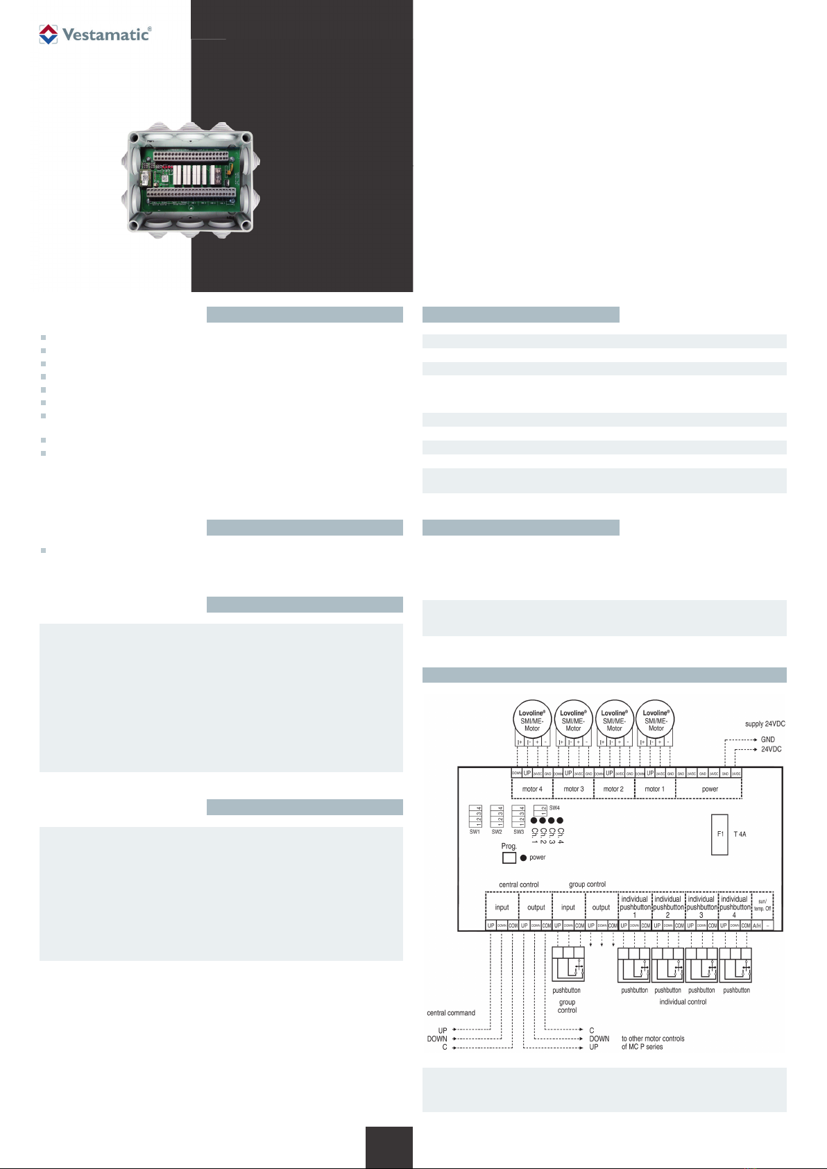
MC P4 LoVo / VRS
3/4
G
Functions, programming and cancelling the wall-mounted radio transmitter
The disposal of electrical equipment and batteries in household waste is strictly
forbidden.
The symbol (dustbin crossed out, in line with WEEE Appendix IV)
indicates
separate collection of electrical and electronic products in EU countries. Do
not dispose of the device or battery in your household waste. Ask your town
or local council about the return and collection systems available in your
area to dispose of this product.
É
Disposal of waste
Programming the wall-mounted radio transmitter
Now open the MC P4 LoVo VRS programming mode.
Example: Programming the wall-mounted radio transmitter to “Ch. 1” = motor 1:
Press the motor control Prog. button until the red “Ch.1” LED flashes. Now press the
ON/UP Q or OFF/DOWN q button on the transmitter.
The 4 red LEDs on the motor control will light up (for 1 second) to indicate that pro-
gramming was successful. Motor 1 channel can now be operated.
Briefly press the ON/UP Q or OFF/DOWN q button = inching mode
Press the ON/UP Q or OFF/DOWN q button for more than 3 seconds = self-locking
To program more channels/transmitter, proceed appropriately.
Cancelling the wall-mounted radio transmitter settings
Now open the MC P4 LoVo VRS programming mode. Press
the motor control Prog. button until the channel (red LED)
that you wish to cancel flashes.
Now press the Prog. button (Fig. C) on the back of the wall-
mounted radio transmitter, the red LED flashes. Now press
the ON/UP Q or OFF/DOWN q button for at least 5 sec-
onds before releasing the button again. The 4 red LEDs on
the motor control will light up (for 1 second) to indicate that
the settings have been cancelled.
Figure C
IDS Function
The IDS (Intelligent Decentralised Sunshade control) feature enables the sun- and
temperature dependant control signals on the central controls to be disabled when
a button is pressed on the decentralised controls. No additional installation work is
required.
In operating mode 4 the IDS-Function enables you to suppress sun- and temperature
dependent extract or extend commands while all other central commands, such as for
privacy and safety protection use are continuously executed. To enable this function
connect a switch to terminal “sun/temp”.
In operating modes 9 and 10, the sun- or temperature-dependent central commands
are masked by pressing the group or individual button. All further sun- and tempera-
ture-dependent retract/extend commands will then be masked for 4 hours. Each addi-
tional operation via the group command or individual command will result in the sun-
or temperature-dependent central commands being masked for a further 4 hours.
After the set period has elapsed, the motor control will be reset automatically and all
sun- and temperature-dependent central controls will then be executed as normal.
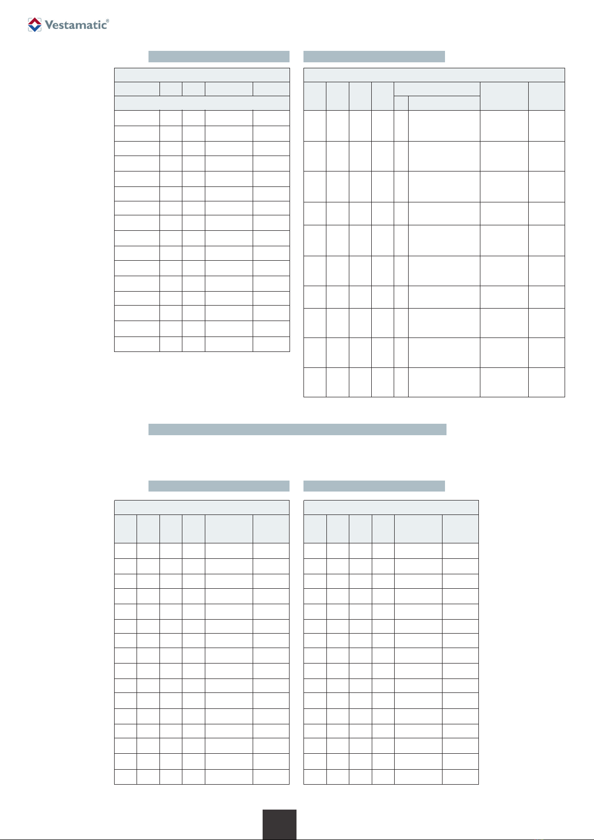
Functional description
Operating mode 1: The group/single command will be stored after 2s;
group/individual control of up to 2s will run the sunshade for the
duration of the command (dead man’s operation).
A central command will run the sunshade for the duration of the
command (dead man’s operation).
Operating mode 2: The group/single command will be stored after 5s;
group/individual control of up to 5s will run the sunshade for the
duration of the command (dead man’s operation).
A central command will run the sunshade for the duration of the
command (dead man’s operation).
Operating mode 3: The group/single command will be stored immediately.
A central command will run the sunshade for the duration of the
command (dead man’s operation).
Operating mode 4: The group/single command will be stored after 2s;
group/individual control of up to 2s will run the sunshade for the
duration of the command (dead man’s operation).
Sun- and temperature dependent central commands can be
suppressed by means of a switch at the terminals “sun/temp”.
Operating mode 5: Special function 1
Operating mode 6: Special function 2
Operating mode 7: The group/single command will be stored immediately.
The central command will be stored immediately.
Operating mode 8: The group/single command will be stored after 2s;
group/individual control of up to 2s will run the sunshade for the
duration of the command.
The central command will be stored after 2s; central operation
of up to 2s will run the sunshade for the duration of the com-
mand.
Operating mode 9: The group/single command will be stored after 2s;
group/individual control of up to 2s will run the sunshade for the
duration of the command (dead man’s operation).
Sun- and temperature-dependent central commands can be sup-
pressed for 4 hours by pressing the group or individual button.
Operating mode 10: The group/single command will be stored immediately.
Sun- and temperature-dependent central commands can be sup-
pressed for 4 hours by pressing the group or individual button.
NOTE FOR OPERATING MODES 9 AND 10!
Pressing the group button will block all 4 outputs for sun- and tempera-
ture-dependent central commands for 4 hours simultaneously. Pressing
an individual button will only block that particular output from sun- and
temperature-dependent central commands for 4 hours.
I
WARNING!
The operating modes 4 to 6, 9 and 10 may only be used in conjunc-
tion with Vestamatic controls with IDS functionality.
Ä
The following descriptions are valid for all MC P4 LoVo versions.
i
3/4
G
RESET-Deleting all radio transmitters
Press the motor control Prog. button for at least 10 seconds. The 4 red LEDs on
the motor control will light up (for 1 second) to indicate that deleting was successful.
Installation note:
While installing the wall remote, please
ensure that the arrow on the back is facing
the ceiling.
i
NOTE:
STOP by pressing the opposite button.
I