CONGRATULATIONS!
ThankyouforpurchasingtheVestaxVMC-180MixingController.Wesuggestthat
youreadthroughthisowner'smanualthoroughlysothatyoumayenjoythefulluse
ofthisproductsafelyandintheknowledgeofallitsspecialfeaturesandsuitable
applications.
CONTENTS
CAUTION 2
IMPORTANTSAFEGUARDS
3
FEATURES 4
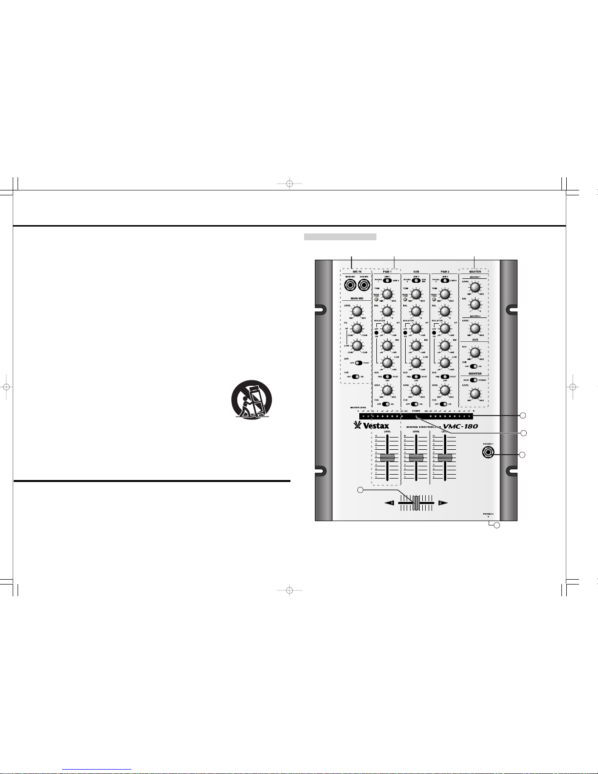
FUNCTIONS 5
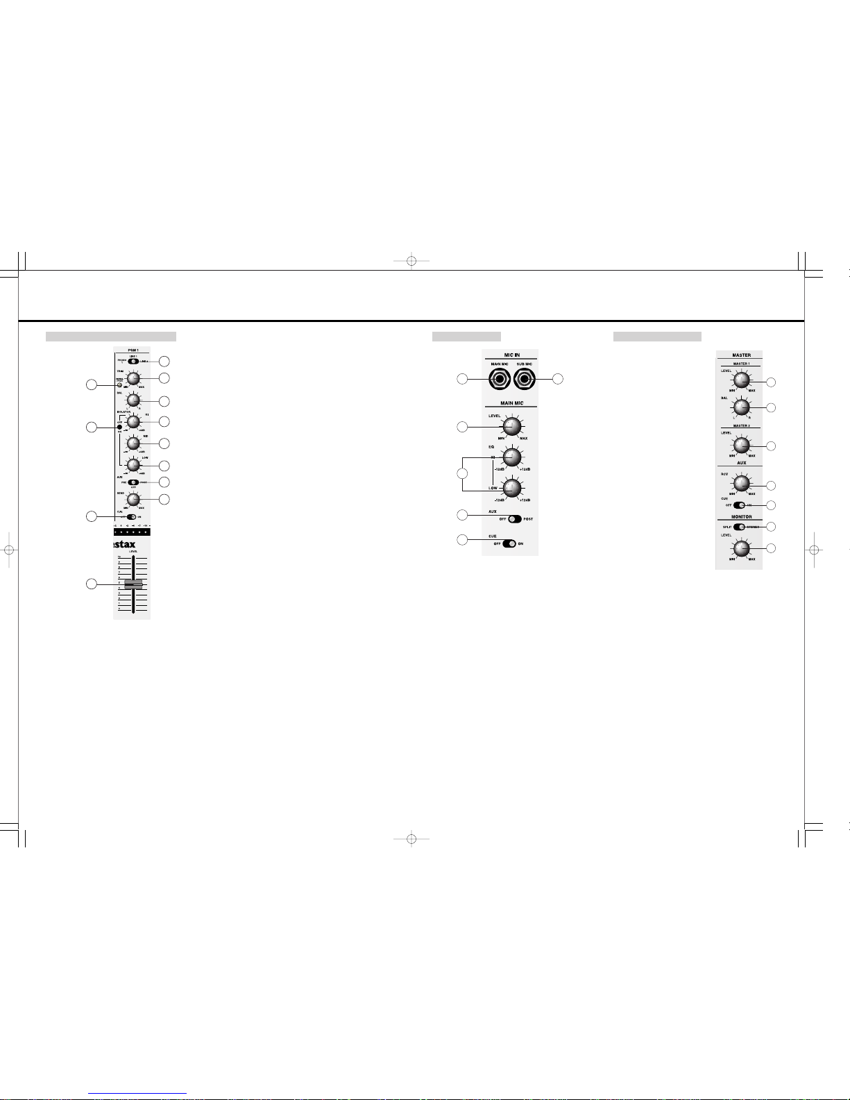
PROGRAMINPUTSECTION
6
MIC.MASTERSECTION
7
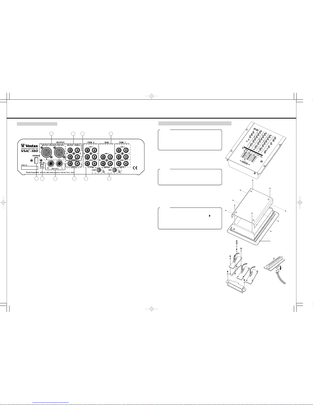
REARPANELSECTION
8
HOWTOCHANGETHEFADERUNIT
9
CONNECTIONS 11
SPECIFICATIONS 12
-2- -3-
CAUTION
RISKOFELECTRICSHOCKDONOTOPEN
CAUTl0N:TOREDUCETHERlSKOFELECTRlCSHOCK
DONOTREMOVECOVER(ORBACK)
NOUSER-SERVICEABLEPARTSINSIDE
REFERSERVlCINGT0QUALIFIEDSERVlCEPERSONNEL
Thelightningflashwitharrowheadsymbol,withinanequilateral triangle,is
intendedtoalerttheusertothepresenceofuninsulateddangerousvoltage
withintheproduct'senclosurethatmaybeofsufficientmagnitudetoconsitutea
riskofelectricshocktopersons.
Theexclamationpointwithinanequilateraltriangleisintendedtoalerttheuser
tothepresenceofimportantoperatingandmaintenance(servicing)instructions
intheliteratureaccompanyingtheappliance.
T0REDUCETHERISK0FFIRE0RELECTRlCSHOCK,DONOT
EXPOSETHISAPPLIANCET0 RAIN0RM0ISTURE.
IMPORTANTSAFEGUARDS
READBEFOREOPERATINGEQUIPMENT
Thisproductwasdesignedandmanufacturedtomeetstrictqualityandsafety
standards.Thereare,however,someinstallationandoperationprecautions
whichyoushouldbeparticularlyawareof.
1.Readinstructions-Allthesafetyandoperating
instructions should be read before the
applianceisoperated.
2.Retaininstructions-Thesafetyandoperating
instructions should be retained for future
reference.
3.HeedWarnings-Allwarningsontheappliance
and in the operating instructions should be
adheredto.
4.Follow Instructions-All operating and use
instructionsshouldbefollowed.
5.Cleaning-Do not use liquid cleaners or
aerosol cleaners. Use a damp cloth for
cleaning.
6.Attachments-Do not use attachments not
recommended by the product manufacturer
astheymaycausehazards.
7.WaterandMoisture-Donotusethisproduct
near water-for example, near a bath tub,
washbowl,kitchensink,orlaundrytub,ina
wetbasement,ornearaswimmingpool,and
thelike.
8.Accessories-Donotplacethisproductonan
unstable cart, stand, tripod, or table. The
productmayfall,causingseriousinjurytoa
child or adult, and serious damage to the
appliance. Use only with a cart,. stand,
tripod,bracket,ortablerecommendedbythe
manufacturer, or sold with product. Any
mountingoftheapplianceshouldfollowthe
manufacturer'sinstructions,andshouldusea
mounting accessory recommended by the
manufacturer.
9.Thisproductshouldneverbeplacednearor
overaradiatororheatregister.Thisproduct
shouldnotbeplacedinabuilt-ininstallation
such as a bookcase or rack unless proper
ventilationisprovidedorthemanufacturer's
instructionshavebeenadheredto.
10.Power sources-This product should be
operatedonlyfromthetypeofpowersource
indicatedonthemarkinglabel.Ifyouarenot
sure of the type of power supply to your
home,consultyourappliancedealerorlocal
powercompany.
11.Lightning-For added protection of this
productduringalightningstorm,orwhenitis
leftunattendedandunusedforlongperiods
oftime,unplugitfromthewalloutlet.Thiswill
prevent damage to the product due to
lightningandpower-linesurges.
12.Overloading-Do not overload wall outlets
andextensioncordsas this canresultina
riskoffireorelectricshock.
13.ObjectandLiquidEntry-Neverpushobjects
of any kind into this product through
openings as they may touch dangerous
voltage points or short-out parts that could
resultina fire or electricshock.Neverspill
liquidofanykindontheproduct.
14.Servicing-Donotattempttoserviceproduct
yourselfasopeningorremovingcoversmay
expose you to dangerous voltage or other
hazards. Refer all servicing to qualified
personnel.