Vestax PMC-05ProSL VCA User manual

O
JUN.2004PMC05ProSLJ○
1
Vestax Corporation
PMC05ProSL-E 04.7.13 11:22 AM ページ 1

OWNER'S MANUAL
PMC05ProSL-E 04.7.13 11:22 AM ページ 2

CONGRATULATIONS!
ThankyouforpurchasingtheVestaxPMC05ProSLMixingController.Wesuggest
thatyoureadthroughthisowner'smanualthoroughlysothatyoumayenjoythefull
use of this product safety and in the knowledge of all its special features and
suitablyapplications.
CONTENTS
CAUTION 2
IMPORTANTSAFEGUARDS 3
FEATURES 4
FUNCTION
S 5
TOPPANELSECTION 5
SAMPLER/DELAYSECTION
7
FRONTPANELSECTION 8
REARPANELSECTION 9
HOWTOUSETHESAMPLER/DELAY
10
HOWTOCHANGETHEFADERUNIT
13
HOWTOCHANGEINPUTSELECTSWITCH
14
CONNECTION 15
SPECIFICATION 15
-2-
CAUTION
RISKOFELECTRICSHOCKDONOTOPEN
CAUTl0N:TOREDUCETHERlSKOFELECTRlCSHOCK
DONOTREMOVECOVER(ORBACK)
NOUSER-SERVICEABLEPARTSINSIDE
REFERSERVlCINGT0QUALIFIEDSERVlCEPERSONNEL
Thelightningflashwitharrowheadsymbol,withinanequilateral triangle,is
intendedtoalerttheusertothepresenceofuninsulateddangerousvoltage
withintheproduct'senclosurethatmaybeofsufficientmagnitudetoconsitutea
riskofelectricshocktopersons.
Theexclamationpointwithinanequilateraltriangleisintendedtoalerttheuser
tothepresenceofimportantoperatingandmaintenance(servicing)instructions
intheliteratureaccompanyingtheappliance.
T0REDUCETHERISK0FFIRE0RELECTRlCSHOCK,DONOT
EXPOSETHISAPPLIANCET0 RAIN0RM0ISTURE.
1.Re
ins
ap
2.Re
ins
re
3.He
an
ad
4.Fo
ins
5.Cl
ae
cle
6.At
re
as
7.W
ne
wa
we
the
8.Ac
un
pr
ch
ap
tri
m
mo
ma
mo
ma
PMC05ProSL-E 04.7.13 11:22 AM ページ 3

-3-
IMPORTANTSAFEGUARDS
READBEFOREOPERATINGEQUIPMENT
Thisproductwasdesignedandmanufacturedtomeetstrictqualityandsafety
standards.Thereare,however,someinstallationandoperationprecautions
whichyoushouldbeparticularlyawareof.
1.Readinstructions-Allthesafetyandoperating
instructions should be read before the
applianceisoperated.
2.Retaininstructions-Thesafetyandoperating
instructions should be retained for future
reference.
3.HeedWarnings-Allwarningsontheappliance
and in the operating instructions should be
adheredto.
4.Follow Instructions-All operating and use
instructionsshouldbefollowed.
5.Cleaning-Do not use liquid cleaners or
aerosol cleaners. Use a damp cloth for
cleaning.
6.Attachments-Do not use attachments not
recommended by the product manufacturer
astheymaycausehazards.
7.WaterandMoisture-Donotusethisproduct
near water-for example, near a bath tub,
washbowl,kitchensink,orlaundrytub,ina
wetbasement,ornearaswimmingpool,and
thelike.
8.Accessories-Donotplacethisproductonan
unstable cart, stand, tripod, or table. The
productmayfall,causingseriousinjurytoa
child or adult, and serious damage to the
appliance. Use only with a cart,. stand,
tripod,bracket,ortablerecommendedbythe
manufacturer, or sold with product. Any
mountingoftheapplianceshouldfollowthe
manufacturer'sinstructions,andshouldusea
mounting accessory recommended by the
manufacturer.
9.Thisproductshouldneverbeplacednearor
overaradiatororheatregister.Thisproduct
shouldnotbeplacedinabuilt-ininstallation
such as a bookcase or rack unless proper
ventilationisprovidedorthemanufacturer's
instructionshavebeenadheredto.
10.Power sources-This product should be
operatedonlyfromthetypeofpowersource
indicatedonthemarkinglabel.Ifyouarenot
sure of the type of power supply to your
home,consultyourappliancedealerorlocal
powercompany.
11.Lightning-For added protection of this
productduringalightningstorm,orwhenitis
leftunattendedandunusedforlongperiods
oftime,unplugitfromthewalloutlet.Thiswill
prevent damage to the product due to
lightningandpower-linesurges.
12.Overloading-Do not overload wall outlets
andextensioncordsasthiscanresultina
riskoffireorelectricshock.
13.ObjectandLiquidEntry-Neverpushobjects
of any kind into this product through
openings as they may touch dangerous
voltage points or short-out parts that could
resultinafireorelectricshock.Neverspill
liquidofanykindontheproduct.
14.Servicing-Donotattempttoserviceproduct
yourselfasopeningorremovingcoversmay
expose you to dangerous voltage or other
hazards. Refer all servicing to qualified
personnel.
PMC05ProSL-E 04.7.13 11:22 AM ページ 4

5
4
12
13
6
FEATURES
-4-
FU
TO
15.Damage Requiring Service-Unplug this
product from the wall outlet and refer
servicingtoqualifiedservicepersonnelunder
thefollowingconditions:
a.When the power-supply cord or plug is
damaged.
b.If liquid has been spilled or objects have
fallenintotheproduct.
c.Iftheproducthasbeenexposedtorainor
water.
d.Iftheproductdosenotoperatenormallyby
followingtheoperatinginstructions.Adjust
onlythosecontrolsthatarecoverdbythe
operating instructions as an improper
adjustmentofother,controlsmayresultin
damage and will often require extensive
workbyaqualifiedtechniciantorestorethe
producttoitsnormaloperation.
e.Iftheproducthasbeendroppedorcabinet
hasbeendamaged.
f. Whentheproductexhibitsadistinctchange
in performance this indicates need for
service.
16.Replacement Parts-When replacement
parts are required, be sure the service
technician has used replacement parts
specified by the manufacturer or have the
same characteristics as the original parts.
Unauthorizedsubstitutionsmayresultinfire,
electricshockorotherhazards.
17.Safety Check-Upon completion of any
serviceorrepairstoproduct,asktheservice
technician to perform safety checks to
determine that the product is in proper
operatingcondition.
18.CartsandStands-Theapplianceshouldbe
used only with a cart stand that is
recommendedbymanufacturer.
19.An appliance and cart combination should
bemovedwithcare.Quickstops,excessive
force, and uneven surfaces may cause the
applianceandcartcombinationtooverturn.
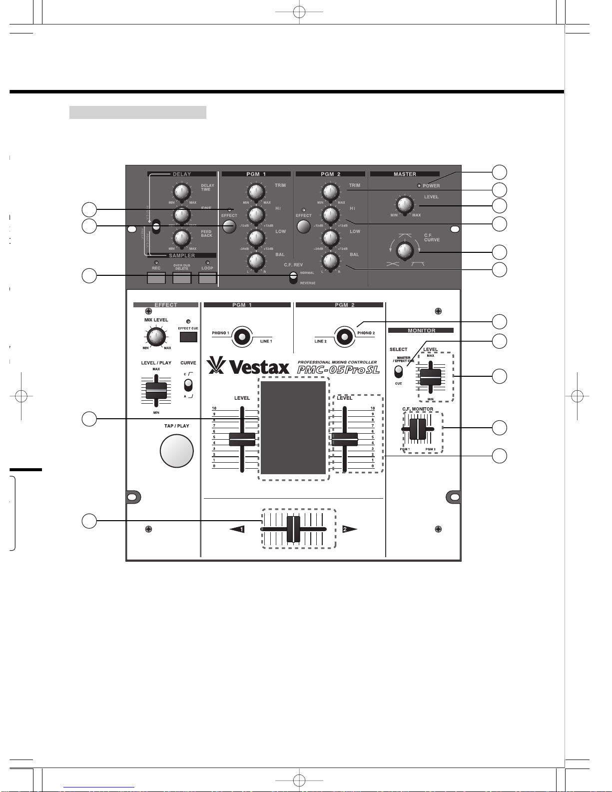
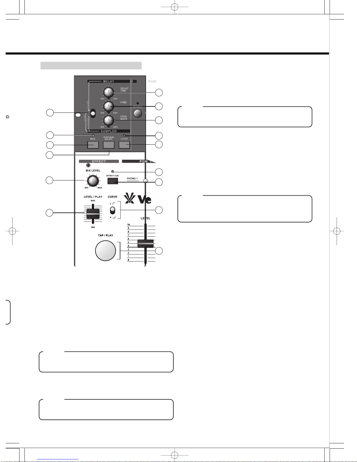
●This machine includes SAMPLER and a DELAY
function .
You can use delay sounds or sampling loop by pushing
the EFFECT switch on the each PGM input channel and
MIC input channel without connecting other effectors.
●You can use over-dubbing for the sampler function.
It is possible to record other phrases in piles in the
phrase which sample recording was carried out.
Therefore, the possibility of DJ plays on the stage grows
further.
Moreover, it is also convenient for DJ play or practice of
scratch.
●By introducing double panel structure, the attachment
screw of the fader circumference on the front panel
causing trouble in the case of scratch performance and
the slot on the panel were eliminated.
The fader location reflecting professional DJ's opinion
realizes high performance.
●The VCA system is adopted as the crossfader section
which serves as an important point in the case of
scratch performance.
Since this system does not go through a sound signal in
the crossfader itself, it realizes a long-life and high-
quality sound.
VCA system: Use a photo-coupler (element which
exchanges brightness change of LED to volume
change), and detect change of the position of the fader
electrically.
Unlike the conventional system, by not letting a
sound signal pass to the fader itself, there is no
degradation of tone quality.
●The input select switch can be set up in the operation
direction(vertical,holizontal, slant)
●Each input is equipped with the equalizer of two bands
of HI and LOW.
Fine compensation for tone quality is possible.
●CF reverse switch is enable to exchange the side PGM1
to PGM2 quickly.
●The curve property of a crossfader can be changed by
the volume on a top panel.
Moreover, you can change a curve property into three
steps by the switch on a fader unit.
●PMC-05pro3 has a select switch for headphone monitor.
It is possible to monitor the signal inputted and the
signal outputted by changing each other.
Since you can monitor master output with lowered
MASTER LEVEL volume, it is convenient to practice
even at night.
qTR
Th
cha
INP
adj
thr
wPG
Th
eac
PMC05ProSL-E 04.7.13 11:22 AM ページ 5

3
2
9
7
8
1
10
16
14
15
11
5
4
12
13
6
-5-
FUNCTIONS
TOPPANELSECTION
ent
ice
rts
the
rts.
ire,
ny
ice
to
per
be
is
uld
ive
the
.
r
on
ds
M1
by
ee
r.
he
ed
ce
qTRIM (PGM1/PGM2)
This pot adjusts the input level of each PGM
channel. Foroptionalacousticquality,set the
INPUT FADER to a position of 7 or 8 then;
adjusttheTRIMsothatasufficientsignalisfed
throughthechannelwithoutdistortion.
wPGM EQ (PGM1/PGM2)
ThispotadjuststheHIandLOWfrequenciesfor
eachPGMchannel.
ePGM BALANCE (PGM1/PGM2)
This pot adjusts the stereo balance level for
eachPGMChannel.Canalsobeusedtoadjust
an unbalanced stereo image. From a center
position a clockwise rotation will increase the
volume of channel R over L. Whereas, a
counter clockwise rotation will increase the
volumeofchannelLoverR.
PMC05ProSL-E 04.7.13 11:22 AM ページ 6

17
21
22
26
29
23
CURVESELECTSW
○
a
○
a
○
b
○
c
○
c
L
L
E
E
V
POSITION POSITIONPOSITION
C.F.
CURVE
○
b
-6-
SA
!7 SA
Thi
sam
Mo
(be
cro
effe
!8 DE
Itis
(0.5
TA
Th
late
!9 FIN
Iti
(0m
rCROSSFADER REVERSE SWITCH
Thisswitchreversestheactionofthecrossfader
byswitchingPGM1and2.
tPGM EFFECT (program effect) SWITCH
It is the switch which sends the signal of each
PGMchanneltobuilt-insampler/delay.Ifitis
pushed,asignalwillbesenttosampler/delay
section,andPGMEFFECTindicatorwilllightup.
yPGM EFFECT INDICATOR
The light will be switched on if PGM EFFECT
SWITCHofeachPGMchannelispushed.
uPOWER INDICATOR
It is the indicator which tells power is supplyed.
PleaseconfirmthatthisindicatorisONbeforeuse.
iMASTER LEVEL
Itisthevolumewhichadjuststhelevelofthesignal
outputtedfromOUTPUTJACKofarearpanel.
oCF CURVE VOLUME
Itisthevolumewhichsetsupthecurveproperty
ofaC.F.CURVE(crossfadercurve).
(a)Curveforalongmix
If CROSSFADER volume is moved, the
volumelevelchangesgentlywithPGM-1and
PGM-2signalinterchangingeachother.
(b)Itisthemiddlecurveof(a)and(c)
(c)Curveforscratchperformance
ThevolumeofCROSSFADERriseupmost
rapidly.
!0 INPUT SELECT SWITCH
Thisswitchisusedtoselecttheinput(LINEor
PHONO)tobesenttoeachPGMchannel.The
upper most position will select PHONO input.
Thisselectorswitchcanalsobeusedtoperform
forTRANSFORMERSCRATCH.Theoperation
directionofthisswitchisselectable.Tochange
theoperationaldirectionofthisswitchremove,
thetoppanelandmakethenecessarythetop
panel.
!1 INPUT FADER (PGM1/PGM2)
This fader is used to adjust the input level of
eachPGMchannel.Theinputfadercurvecan
bechangedusingaswitchlocatedontheunit
itself. This fader is a detachable for making
easyreplacement.Ensurethatyoureplacewith
anIF-05PCVwhen itwillwornout. Formore
comprehensive instructions please refer to the
"HOWTOCHANGETHEFADERUNIT"section
ofthisuserguide.
!2 INPUT LEVEL METER
TheLEDlevelmetersindicatethesignallevelof
eachPGMchannel.
!3 CROSSFADER
Whentheinput level of PGM1andPGM2are
properly set, PGM1 will be heard with the
crossfader set to the left side. PGM2 will be
heardwiththecrossfadersettotherightside.
Whenthe crossfaderisset inthecenter,both
programswillbeheard.Thisisdetachablefader
fortheeasyreplacementwith"CF-PCV"whenit
iswornout.Itistheswitchwhichchoosesthe
signal (PHONO and LINE) inputted into each
PGMchannel.
!4 MONITOR LEVEL
Itisthefaderwhichadjuststhevolumeofthe
headphoneconnectedtoPHONESjack.
!5 C.F.MONITOR FADER5
It is the fader which chooses the signal
monitored by headphone. Depends on the
positionofaknob,thesignalbalanceofPGM-1
andPGM-2changeslikeCROSSFADER.
!6 MONITOR SELECT SWITCH
Itistheswitchwhichchangesthemonitorform
ofheadphone.
MASTER/EFFECT CUEWhen a EFFECT
CUEswitchisOFF,itcanactasthemonitorof
the signal outputted from LINE OUT jack
.Moreover,whenaEFFECTCUEswitchisON,
itcanactasthemonitoronlyforofthesignal
outputtedfrombuilt-insampler/delay.
CUEItcanactasthemonitorofthesignalof
PGM-1 or PGM-2 chosen by C.F.MONITOR
fader.WhenC.FMONITORfaderissetupinthe
center position, you can monitor the signal of
bothPGM-1andPGM-2.
No
Wh
up
No
Wh
up
Notes
Even if C.F.REVERSE switch is set to the
"REVERSE"side,C.F.MONITORvolumeisnot
REVERSE(ed).
PMC05ProSL-E 04.7.13 11:22 AM ページ 7

18
19
25
24
28
27
30
20
17
21
22
26
29
23
31
-7-
SAMPLER/DELAYSECTION
!7 SAMPLER/DELAY SELECT SWITCH
Thisswitchselectstheeffecterfunctiontoeither
samplerordelay.
Moreover, in the sampler side, either Pre I.F.
(before a inputfader) or Post C.F. (after a
crossfader) can be chosen which signal is
effectedwiththesameswitch.
!8 DELAY TIME
Itisthevolumewhichsetsupdelaytimeroughly
(0.5msec-1450msec).
TAP/PLAYswitchcanalsosetupthedelaytime.
Thepriorityisgiventothedirectionoperatedat
latest.
!9 FINE
Itisthe volumewhichsetsupdelay time finely
(0msec-90msec).
@0 FEEDBACK
It is the volume which adjusts the amount of
feedbacks(timeofrepeat).Thenumberoftimes
becomes1timewhenthepotturnedtotheleft,
andthenumberoftimesincreaseswhenthepot
turnstotheright.
@1 REC SWITCH
Itistheswitchwhichoperatesstopandstartof
recording. REC indicator lights up during
recording.Overdubbingwillbestartedwhenthis
REC switch is pushed during LOOP playback.
Themaximumrecordingtimeis23.8seconds.If
itrecords11.9secondsandmore,youcannot
use overdubbing function. If 11.9 seconds and
23.8 seconds are approached, an indicator will
blink.
@2 REC INDICATOR
It is the indicator which tells a recording
operation. If recording time passes over 8.9
seconds,itwillwarnwithindicatorstartingblink
and tells approaching marginal time (11.9
seconds)ofoverdubbing.Moreover,ifitpasses
over 20.8 seconds , it will warn with indicator
startingblinkagainofapproaching23.8seconds
ofthelongestrecordingtime.
@3 OVERDUB DELETE SW
Itistheswitchwhichdeletesthephraseofover-
dubbing. If this OVERDUB DELETE switch is
pushedduringLOOPplayback,itwillleaveonly
thephraserecordedfirstandthephraseofover
dubbingwillbedeleted.
@4 LOOP SWITCH
ItistheswitchwhichoperatesLOOPmode.Ifa
switchispushed,itwillbesetasloopplayback
mode and LOOP indicator will light up.If this
LOOP switch is pushed during loop playback,
loop playback stops and it will be in a loop
playback standby.(Loop playback mode is not
canceledatthistime.)IfthisLOOPswitchis
pushed during loop playback standby, loop
playbackmodewillbecanceled.
@5 LOOP INDICATOR
It is the indicator which tells ON/OFF in loop
playbackmode.Whenloopplaybackmodeis
ON,anindicatorlightsup.
ore
the
tion
elof
are
the
l be
ide.
both
ader
enit
the
ach
the
gnal
the
M-1
orm
CT
rof
jack
ON,
gnal
lof
OR
the
l of
Notes
WhenSAMPLER/DELAYSELECTswitchisset
uptootherthanDELAYmode,itdosenotwork.
Notes
WhenSAMPLER/DELAYSELECTswitchisset
uptootherthanDELAYmode,itdosenotwork.
Notes
WhenSAMPLER/DELAYSELECTswitchisset
uptootherthanDELAYmode,itdosenotwork.
Notes
WhenSAMPLER/DELAYSELECTSWITCHis
setuptootherthanSAMPLERmode,itdose
notwork.
he
ot
PMC05ProSL-E 04.7.13 11:22 AM ページ 8

43
40
-8-
RE
FRONTPANELSECTION
@6 MIX VOLUME
Itisthevolumewhichadjuststhemasteroutput
levelofSAMPLER/DELAY.Whenyouwantto
monitor the signal outputted from SAMPLER /
DELAY by headphone, please set this volume
minimum.
@7EFFECT CUE SWITCH
ItistheswitchformonitorsoundofSAMPLER/
DELAY by headphone. When the switch is
pushed,MONITORSELECTswitchischangedto
aMASTER/EFFECTCUEsides,youcanmonitor
ofthesignaloutputtedfromSAMPLER/DELAY.
Whenaswitchison,EFFECTCUEindicatorlights
up.
@8 EFFECT CUE INDICATOR
It is the indicator which tells ON/OFF state of
EFFECT CUE switch. The light is up when a
EFFECTCUEswitchison.
@9 LEVEL/PLAY VOLUME
Itisthevolumewhichadjuststheeffectlevelof
SAMPLER/DELAY. In the SAMPLER mode,
the fader operates start/stop of a phrase of
sampling. If volume is raised, it will start
playbackwiththelevelaccordingtothescaleof
thevolume,andifitissetatminimum,playback
willstop.
#0 CURVE SWITCH
Itistheswitchwhichsetsupthevolumecurve
propertyofLEVEL/PLAYvolume.Atthetimeof
the"C"side,levelofsoundincreaserapidly.And
atthe"A"side,thelevelincreaseloosely.Itis
convenientifyouuseproperlyintherighttimeof
DELAYmodeandSAMPLERmode.
#1 TAP SWITCH
In the DELAY mode, switch works to set up
delay time. And the button blinks according to
theset-updelaytime.IntheSAMPLERmode,it
worksasaswitchforstarting.Duringplayback,
thebuttonlightsup.
#2 MIC input jack
ItistheinputjackforMIC.
#3 MIC EFFECT SWITCH
Itistheselectswitchwhichsendsthesignalofa
MIC channel to built-in SAMPLER/ DELAY. If it
pushed, a signal will be sent to SAMPLER /
DELAY, and MIC EFFECT SEND indicator will
lightup.
#4 MIC EFFECT INDICATOR
LED will light up when MIC EFFECT switch is
pushed.
#5It is the volume which adjusts the level of the
microphoneconnectedtoMICinputjack.
#6Itisajackonlyforheadphone.Pleaseusethe
stereoheadphoneoverimpedance8ohms.
MIN MAX
LEVEL
EFFECT
MIC IN
MIC
36
32
34
33
35
MIC LEVEL VOLUME
PHONES (headphone) jack
#7 FO
It i
wo
you
isc
up
#8 LIN
Itis
pla
pla
sup
#9 PH
Iti
tur
add
hea
$0 MA
Itis
(In
con
LIN
$1 GN
Itis
turn
hum
turn
PMC05ProSL-E 04.7.13 11:22 AM ページ 9

DC 15V
INPUT - PGM 1INPUT - PGM 2
POWER
LINE 2
PHONO 2
1
2
GND 2
LRLR
LINE 1
FOOT SW
(REC)
PHONO 1
GND 1
LR
OUTPUT
MADE IN CHINA UNDER LICENCE
OF VESTAX TOKYO, JAPAN
SERIAL NO.
43
42 41 3738 39
40
-9-
REARPANELSECTION
lof
de,
of
tart
of
ack
rve
of
nd
Itis
eof
up
to
e,it
ck,
the
the
#7 FOOT SWITCH JACK
It is the jack for a foot switch. The foot pedal
worksasaRECswitchonthefrontpanel.When
youwanttorecordscratchplaywithouthands,it
isconvenient.Pleaseusethefootpedaltomake
up(short)whenpushed.
#8 LINE INPUT JACK
ItisajackforCDplayer,CD-R/RWplayer,MD
player,theTAPEdeck,DATandVTR,andaDVD
player.TheRCApinplug(unbalancedinput)is
supported.
#9 PHONO INPUT JACK
Itisajackfora turntable. Please connect the
turntable to which MM cartridge was set. In
addition,inuseofaMCtypecartridge,optional
headamplifierisneeded.
$0 MASTER OUT JACK
Itisajackforamplifier,masterconsole,etc.
(In the case of the amplifier for audios, please
connect with an input jack with the notation of
LINEorAUX.)
$1 GND TERMINAL
Itistheterminalthatconnectstheearthwireofa
turntable. In order to decrease a noise and a
hum,pleasebesuretoconnectwhenyouusea
turntable.
$2 POWER JACK
It is the jack that connects a power supply
adapter. Please connect the original adapter
(DC-15A).
$3 POWER SWITCH
It is on/off-switch of a power supply. When a
power supply switch is on, POWER indicator
lightsuponthefrontpanel.
Notes
Incase youoperatethisswitch,pleasemake
sure to lower volumes, of connected power
amplifier,orthepoweristurnedoff.
Keepinmindthatthereisapossibilityofitnot
onlyhavingabadinfluenceonpoweramplifier
on a speaker, but also a noise entering, and
damaging itself in case a power supply is
turnedon.
PMC05ProSL-E 04.7.13 11:22 AM ページ 10

-10-
HOW TO USE THE SAMPLER/DELAY
Delay
PleasecheckbeforeoperationthatsoundhascomeoutfromaMIXERortheconnectedspeaker.
1.Set it as DELAY mode
SAMPLER/DELAY SELECT switch is set to a "DELAY"
side.
2. Set up delay time
StrikeTAPswitchseveraltimes,listeningtomusicsource
ifyouwanttosetdelaybythespeakerorheadphone.(At
thistime,thebuttonblinksaccordingtothetempothatthe
buttonstruck.)
3. Choose the channel to which
an effect is applied
ItchecksthatpushedPGMEFFECTswitchofthechannel
(PGM-1or2)youwanttoeffect,
andcheckPGMEFFECTindicatorislightsupandlisten
totheeffectsoundbypushingEFFECTCUESWITCH.
(caution:IftheLEVEL/PLAYVOLUMEisminimum,you
can't monitor effect sound. Please set LEVEL/PLAY
VOLUMEtosuitablelevel.)
4. Apply the effect.
An original sound (sound which had come out of the
speakerfromthefirst),andaddtheeffectsoundbyraising
MIX volume and LEVEL/PLAY volume. At this time, if
CURVEswitchissettothe"A"side,effectsoundcanbe
mixedgradually.
SAM
NOR
PMC05ProSL-E 04.7.13 11:22 AM ページ 11

-11-
Y"
rce
(At
the
nel
ten
you
AY
the
ing
, if
be
1. Set it as SAMPLER mode.
SAMPLER/DELAYSELECTswitchissettoa"PRE-I.F"
or"PRE-C.F"side.Youcanrecordthesignalpassedbefore
inputfader on PRE-I.F,and the signal passed before
crossfaderonPREC.F.
2. Select the channel to record
PleasepushPGMEFFECTswitchofthechannel(PGM-1
or 2) you want to record. And check PGM EFFECT
indicatorlightsup.
3. Record
REC switch is pushed hearing the output sound from
headphoneoraspeaker,andrecordingisstarted.
Recording will be stopped if a REC switch is pushed
again. (Keep in mind that you can't use overdubbing
functionwhenyourecordover11.9seconds.)
RECINDICATORblinkswhenthelimitofoverdubbingis
coming. If you continue the recordings over the limit of
over dubbing, indicator blinks again when the limit of
recordingtimeiscoming.
4. PLAYBACK
SetMIXvolumetosuitablelevel.
PlaybackstartsatthesametimeLEVEL/PLAYVOLUME
is raised. By pushing LOOP switch, loop playback will
starts.
SAMPLER
NORMALRECORDING
PMC05ProSL-E 04.7.13 11:22 AM ページ 12

fig.a
fig.c
TOPP
MAIN
-12-
OVERDUBBING
1.Turn on loop playback mode
Push LOOP switch and set to loop playback mode.
(PleasecheckthattheLOOPindicatorisonatthistime.)
2. Start loop playback
LEVEL/PLAYvolumeisraisedandplaybackisstarted.
3. Select the channel to record
Push switch that you want to record and check the
EFFECTindicatorison.
4. Over dubbing
Duringloopplayback,pushRECswitchatthepointyou
wanttostartoverdubbing.Overdubbingwillbestoppedif
aRECswitchispushedagain.(Incaseascratchplayis
recorded,whenbothhandsarefull,itisconvenientthata
footpedalisconnectedtoFOOTjackandyoucanuseit
asaRECswitch.)
5. Playback
WhenyouraiseMIXfaderwithLEVEL/PLAYvolumebeing
raised,playbackstartsatthesametime.
■Ho
①A
L
L
②A
N
f
③A
p
u
p
④
c
c
⑤
⑥
⑦
s
HO
PMC05ProSL-E 04.7.13 11:22 AM ページ 13

fig.a fig.b
fig.d
fig.c
DRIVER
DRIVER
Insertthe
multi-cable
connecter
Setswitchto"PMC"position
TOPPANEL
MAINPANEL
KNOB
-13-
de.
.)
the
you
dif
yis
ta
eit
ing
■Howtoremoveatoppanel
①Asshowninfig-a,pleaseremovetheknobofINPUT
LEVEL volume,CROSS FADER volume, MONITOR-
LEVELvolume,C.F.MONITORvolume,andLEVEL/
PLAYvolume.(Atotalofsixpieces)
②Asshowninfig-a,pleaseuseaplusscrewdriver(size:
No.1),andremovethescrewoffourpointswhichis
fixingthetoppanel.
③Asshown in fig-b,pleaseremove the screwof two
points which is fixing the fader panel, and raise
upwards the whole fader unit, after removing a top
panel.
④Please pull and remove the connector which has
connectedthemainpartsidewiththefaderunit.(Be
carefulnottobendthepinofaconnectorinthiscase)
⑤Removethefaderknobofnewfaderunit.
⑥Attachmulti-cableconnectortonewfaderunit.
⑦Positionthenewfaderunitcarefullyandsecurewith
screws.
HOWTOCHANGETHEFADERUNIT
PMC05ProSL-E 04.7.13 11:22 AM ページ 14

PHONO
LINE
fig.e fig.f
DRIVER
-14-
CO
SPE
①removethetoppanelinthesameprocedure.
②Removethetwoscrewswhichfixtheswitchpanel,fix
the switch panel, and remove the switch unit from
positioninmixer.(Seefig-e)
③Changethedirection,andthesecurewithscrews.
④Replacethetoppanelandsecurewithscrews.
INP
OU
EQ
etc
FOOTSW(REC)
①removethetoppanelinthesameprocedure.
②Removethetwoscrewswhichfixtheswitchpanel,fix
the switch panel, and remove the switch unit from
positioninmixer.(Seefig-e)
③Carefully remove the multi cable connector from the
switchunit(Seefig-f)
④Attachmulticableconnectortonewswitchunit.
⑤Positiontheswitchunitcarefully,andthesecurewiththe
screws.
Howtochangeinputselectswitch
Howtochangethedirectionoftheswitch
removethe
multi-cableconnector
PMC05ProSL-E 04.7.13 11:22 AM ページ 15

-15-
CONNECTION
SPECIFICATION
PHONOIN:PGM-1〜2(RCAPIN/UNBLANCEDdBv)
LINEIN:PGM-1〜2(RCAPIN/UNBLANCEDdBv)
MICIN:(Φ6.3PHONE/UNBLANCEDdBv)INPUT
OUTPUT
EQ
etc.
MASTEROUT
EQUALIZER :HI
:LOW
:MID
FREQUENCYRESPONS :LINE
S/NRATIO :LINE
CROSSTALK :C.F.
THD
POWERSUPPLY
POWER
WEIGHT
SIZE(W×H×D)
NOMINALINPUTLEBEL
-50dBv
-45dBv
-10dBv
IMPEDANCE
3kΩ
45kΩ
10kΩ
20Hz〜20kHz ±1dB
75dB≧
80dB≧
<0.01%
DC-15A 500mA
10W
4kg
(W×H×D)103×320×262(mm)
NOMINALOUTPUTLEBEL
-10dBv
10kHz(±12dB) SHELVINGTYPE
60Hz(+12,-24dB)UPEAKINGTYPET:-∞
IMPEDANCE
220Ω
PHONO1 PHONO2
LINE1 LINE2
FOOTSW(REC)FOOTSW(REC)FOOTSW(REC)
the
the
tor
PMC05ProSL-E 04.7.13 11:22 AM ページ 16
Other manuals for PMC-05ProSL VCA
1
Table of contents
Other Vestax Recording Equipment manuals

Vestax
Vestax QFO LE User manual

Vestax
Vestax TR-1 User manual

Vestax
Vestax DSG-200 User manual

Vestax
Vestax DCR-2500F User manual

Vestax
Vestax VCI-100MKII User manual

Vestax
Vestax GE-31A User manual

Vestax
Vestax DDG-X2 User manual

Vestax
Vestax VCM-100 User manual

Vestax
Vestax DSG-300 User manual

Vestax
Vestax QFO User manual