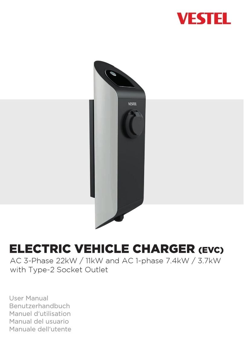
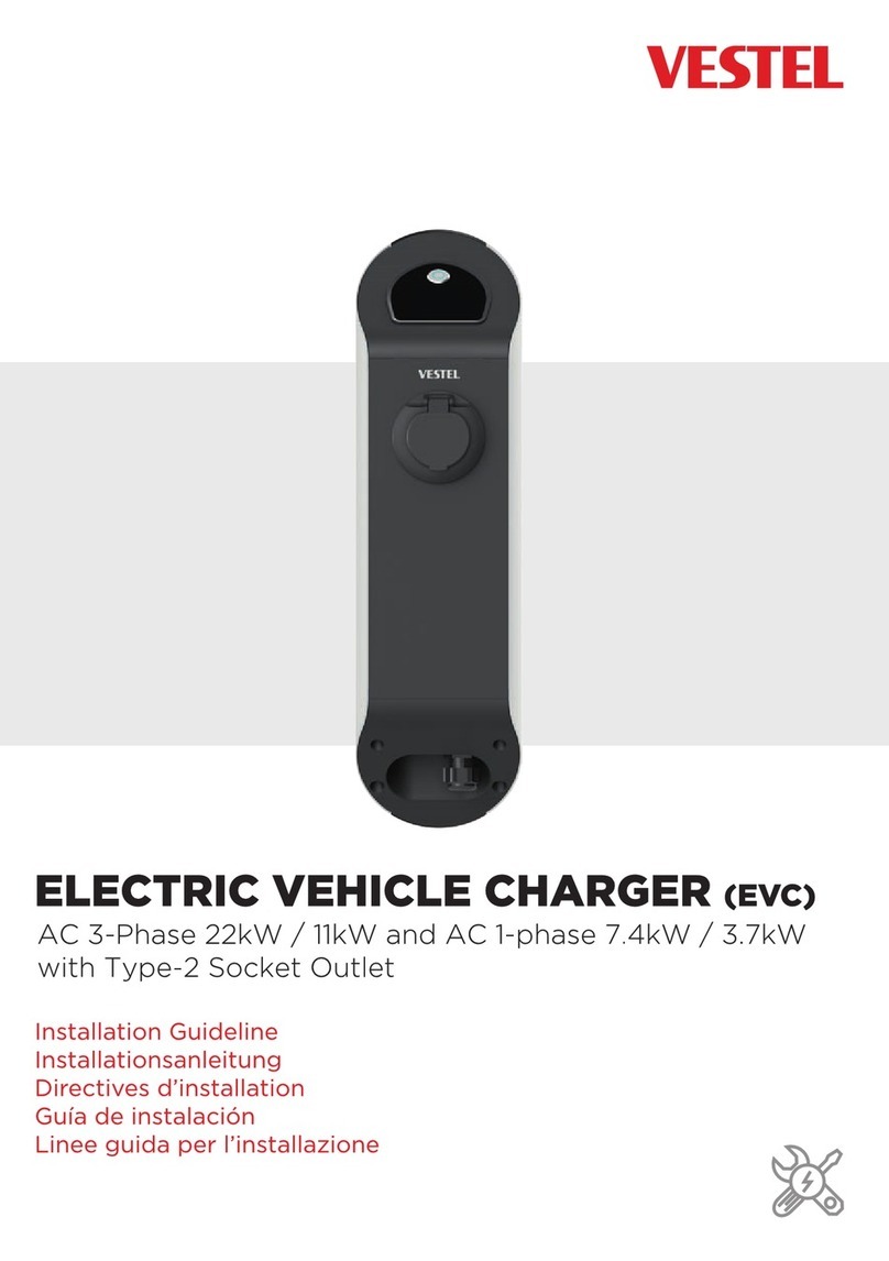
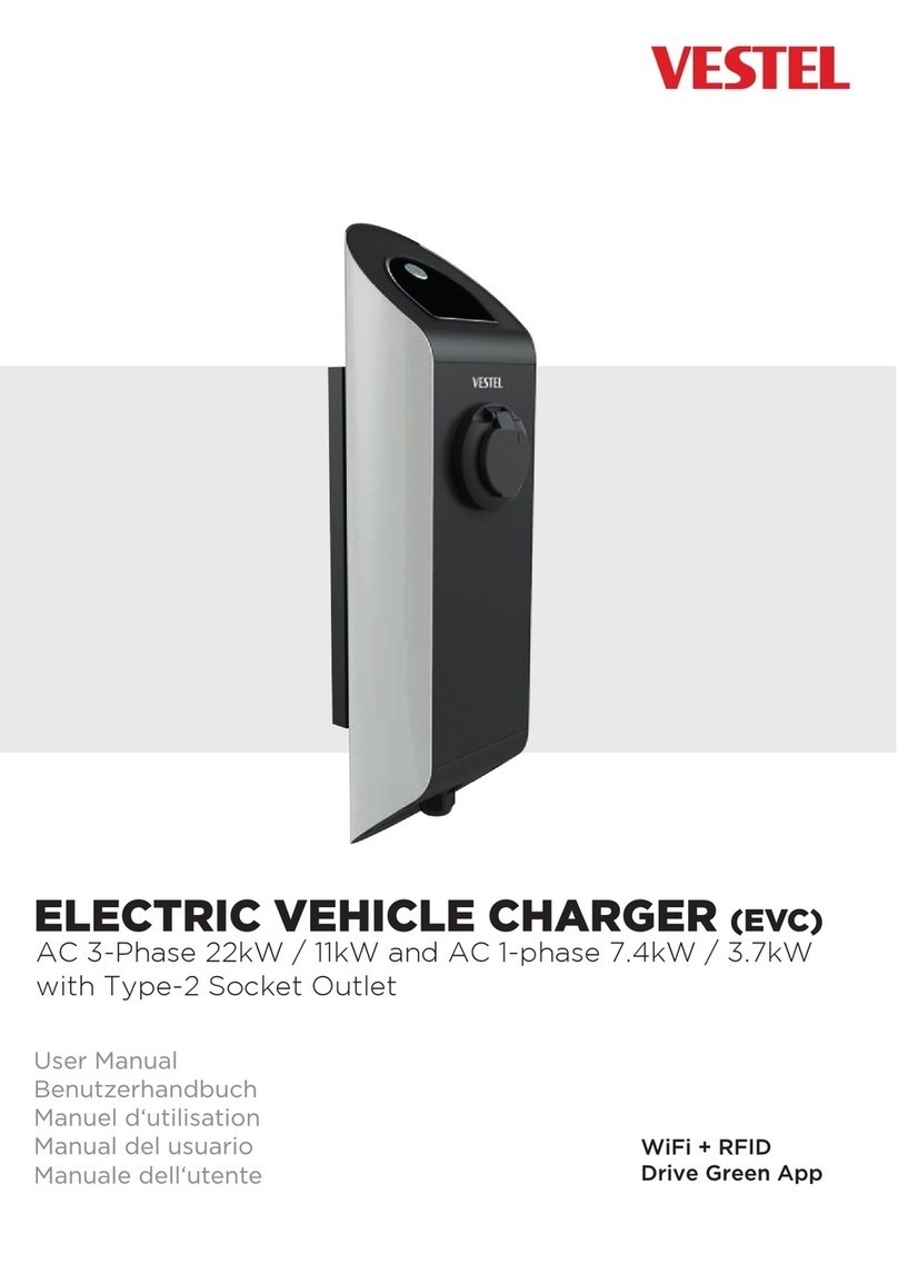
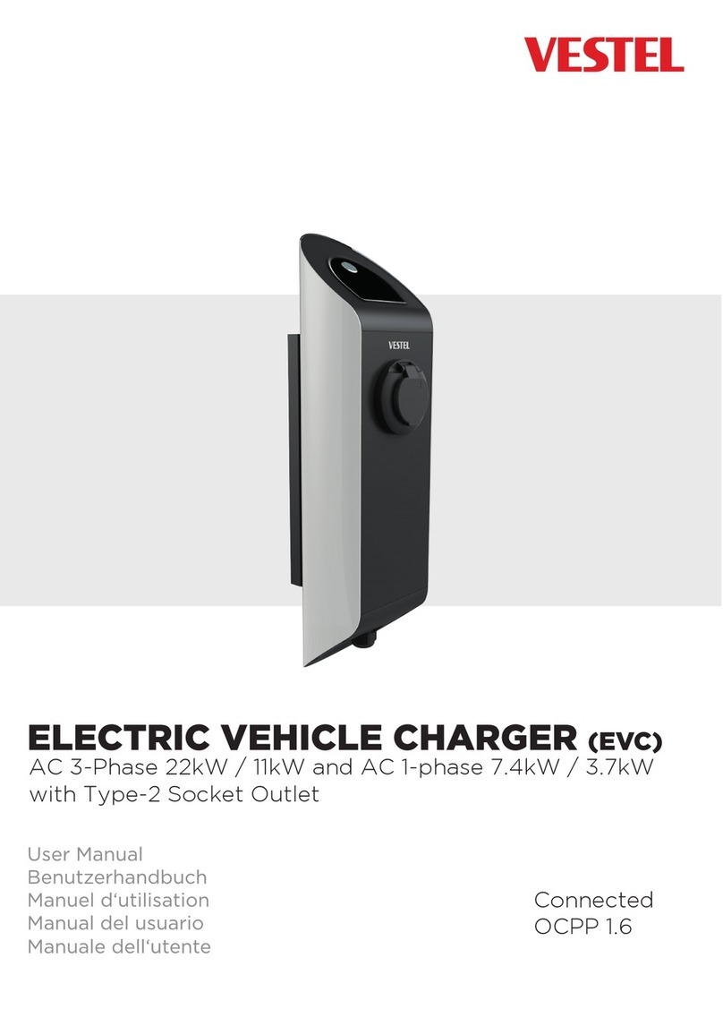
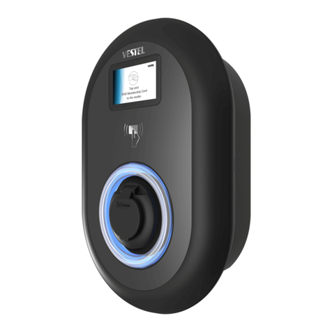
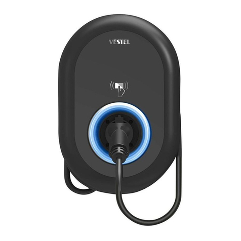
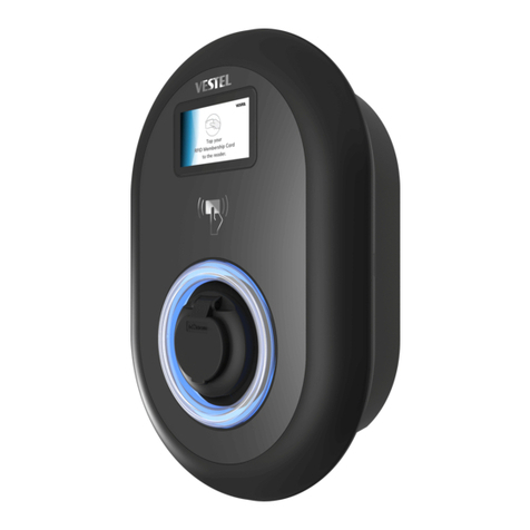
VESTEL EVC04-AC7 User manual

ELECTRIC VEHICLE CHARGER
User Manual
Benutzerhandbuch
Manuel Utilisateur
Manual de usuario
Manuale dell’utente
Instrukcja obsługi
Brugermanual
Brukermanual
Ohjekirja
Användarmanual
Lietotāja rokasgrāmata
Vartotojo vadovas
Használati utasítás
Uživatelský manuál
Kullanım Kılavuzu
Ръководство за употреба
Посібник користувача
Руководство пользователя

English - 1 -
SAFETY PRECAUTION
CAUTION
RISK OF ELECTRIC SHOCK
CAUTION: VESTEL ELECTRIC VEHICLE CHARGER DEVICE SHALL BE
MOUNTED BY A LICENSED OR AN EXPERIENCED ELECTRICIAN
AS PER ANY REGIONAL OR NATIONAL ELECTRIC REGULATIONS
AND STANDARDS IN EFFECT.
WARNINGS
WARNING : Danger of injury or electric shock. Prior to connecting AC mains cable or EV
charger electric supply, disconnect the power on AC mains side or the load centre.
WARNING REGARDING
1) Prior to mounting your charging station and the charger on the pole, read these instructions.
2) Do not mount your charging station in close proximity to heating appliances.
3) Use the wall mounting screws and other accessories.
4) This appliance is classified as indoor and outdoor mount compatible.
Compatible Chargers
EVC04-AC7
EVC04-AC7A
EVC04-AC7A-T2P
EVC04-AC7A-T2S
EVC04-AC7A-T1P
EVC04-AC22
EVC04-AC22A
EVC04-AC22A-T2P
EVC04-AC22A-T2S
Tools for Mounting:
•(1x) Drill
•(1x) Drill bit Ø10mm
•(1x) Hammer (Steel Handle)
•(1x) Torks Safety Allen Wrench
•(1x) M6 Scew Driver
•(1x) 13mm open end wrench (for Steel dowel)
•(1x) Side Cutter
•(1x) Volt Indicator
•(1x) Sleeve Tightening Apparatus or Wrench

English - 2 -
MOUNTING INSTRUCTIONS
1. Mount the stand on the concrete oor. (Figure.1)
895
1150
Figure 1
2. Highlight the location where the stand will be mounted with a pen and drill a hole, then place the part
from the top to the stand. (Figure.2)
Figure 2

English - 3 -
3. Pull the cable to the stand with a rope (guide). First hammer the in the screws to the drilled holes with
the hammer and then x the screws with a wrench and x them on the concrete oor. (Figure.3)
Figure 3
4. In order to mount the stand and the cabling work, the appliance’s cover must be opened. Remove the
screws as shown in Figure 4 and open the cover of the product, replace the ttings by following the steps
in the gure. (Figure 4.a 4.b 4.c 4.d).
Figure 4
Figure 4a Figure 4b Figure 4c Figure 4d

English - 4 -
5. As seen in Figure 5, first attach the mounting part, then mount on the stand. Then mount the appli-
ance by screwing and fixing on the mounting part.
M6x12 Screw (ZN İnbus), Tightening Torque: 4 Nm ± 1 Nm
Figure 5
6. After attaching the mounting part on the stand, adjust the cable that will be mounted as seen in Fig-
ure.6.
11cm
Figure 6

English - 5 -
7. Pass the cable through the charger’s sleeve and based on the product’s phase (Single Phase 3-Phase)
connect the cable as shown in the installation manual.
Figure 7
8. After connecting the appliance cables, tighten the sleeve as shown in Figure 8.
Figure 8

English - 6 -
9. If the appliance will be mounted on the stand as standalone, the empty holes can be closed with D6 (4
pcs) and D53 (1 pcs). (Figure.9)
Figure. 9
10. After mounting the appliance on the stand, it will look like below. (Figure. 10)
Figure. 10

Deutsch - 1 -
SICHERHEITSHINWEISE
ACHTUNG
STROMSCHLAGGEFAHR
ACHTUNG: DAS VESTEL-LADEGERÄT FÜR ELEKTROFAHRZEUGE DARF
NUR VON EINER ZUGELASSENEN UND ERFAHRENEN
ELEKTROFACHKRAFT IN ÜBEREINSTIMMUNG MIT ALLEN
GELTENDEN REGIONALEN UND NATIONALEN VORSCHRIFTEN
UND NORMEN FÜR ELEKTROFAHRZEUGE MONTIERT WERDEN.
WARNUNGEN
WARNUNG: Stromschlag- oder Verletzungsgefahr. Trennen Sie die Stromversorgung vom
Netz oder vom Ladegerät, bevor Sie das Netzkabel und das EV-Ladegerät anschließen.
MONTAGEHINWEISE
1) Lesen Sie diese Anweisungen, bevor Sie die Ladestation und das Ladegerät am Pfosten montieren.
2) Installieren Sie die Ladestation nicht in der Nähe von Heizgeräten.
3) Verwenden Sie die angegebenen Pfostenbefestigungsschrauben und anderes Zubehör.
4) Dieses Gerät ist für die Montage im Innen- und Außenbereich ausgelegt.
Kompatible Ladegeräte
EVC04-AC7
EVC04-AC7A
EVC04-AC7A-T2P
EVC04-AC7A-T2S
EVC04-AC7A-T1P
EVC04-AC22
EVC04-AC22A
EVC04-AC22A-T2P
EVC04-AC22A-T2S
Für die Montage benötigtes Werkzeug:
• (1x) Bohrmaschine
• (1x) Bohrspitze Ø10mm
• (1x) Hammer (mit Stahlgriff)
• (1x) Torx-Sicherheits-Inbusschlüssel
• (1x) M6-Schraubendreher
• (1x) 13mm Maulschlüssel (für Stahldübel)
• (1x) Seitenmeißel
• (1x) Spannungsprüfer
• (1x) Hülsencrimpgerät oder
Schraubenschlüssel
Deutsch - 2 -
MONTAGESCHRITTE
1. Befestigen Sie den Ständer an der gewünschten Stelle auf dem Betonboden. (Abbildung 1)
895
1150
Abbildung 1
2. Bestimmen Sie mit einem Stift die Stelle, an der der Ständer montiert werden soll, und bohren Sie mit
dem Bohrer ein Loch. Führen Sie dann die Hose wie abgebildet von oben in den Ständer ein. (Abbil-
dung 2)
Abbildung 2

Deutsch - 3 -
3. Ziehen Sie das Kabel mit einem Seil (Führung) zum Ständer. Schlagen Sie die Schrauben zuerst mit
einem Hammer in die Bohrlöcher, ziehen Sie die Schrauben dann mit einem Schraubenschlüssel fest
und befestigen Sie den Ständer am Betonboden. (Abbildung 3)
Abbildung 3
4. Für die Montage und Verkabelung des Produkts muss die Abdeckung des Produkts geöffnet werden.
Entfernen Sie die Schrauben, wie in Abbildung 4 gezeigt, und öffnen Sie die Abdeckung des Produkts.
Bringen Sie die Befestigungen wieder an, indem Sie den Schritten in der Abbildung folgen. (Abbildung
4.a 4.b 4.c 4.d)
Abbildung 4
Abbildung 4a Abbildung 4b Abbildung 4c Abbildung 4d

Deutsch - 4 -
5. Montieren Sie, wie in Abbildung 5 gezeigt, zuerst das Montageteil am Ständer. Befestigen Sie dann das
Produkt durch Verschrauben am Ständer.
M6x12 Schraube (ZN Inbus), Anzugsdrehmoment: 4 Nm ± 1 Nm
Abbildung 5
6. Stellen Sie nach der Montage des Montageteils am Ständer das zu montierende Kabel wie in Abbil-
dung 6 gezeigt ein.
11cm
Abbildung 6

Deutsch - 5 -
7. Führen Sie das Kabel durch den Stecker des Ladegeräts und schließen Sie das Kabel gemäß der Pha-
se Ihres Produkts (1 Phase, 3 Phase) an, wie im Installationshandbuch angegeben.
Abbildung 7
8. Ziehen Sie nach dem Verdrahten des Produkts die Muffe wie in Abbildung 8 gezeigt fest.
Abbildung 8

Deutsch - 6 -
9. Soll das Produkt einzeln auf dem Ständer montiert werden, können die rückseitigen Leerlöcher mit
D6 (4 Stück) und D53 (1 Stück) verschlossen werden. (Abbildung 9)
Abbildung 9
10. Sobald das Produkt auf dem Ständer montiert ist, sieht es wie folgt aus. (Abbildung 10)
Abbildung 10

Français - 1 -
PRÉCAUTIONS DE SÉCURITÉ
ATTENTION
RISQUE DE CHOC ÉLECTRIQUE
ATTENTION: L'INSTALLATION DU CHARGEUR DE VÉHICULE
ÉLECTRIQUE VESTEL NE DOIT ÊTRE EFFECTUÉE QUE PAR UN
ÉLECTRICIEN TITULAIRE D'UNE LICENCE ET EXPÉRIMENTÉ,
CONFORMÉMENT À TOUS LES RÈGLEMENTS ET NORMES
APPLICABLES EN MATIÈRE D'ÉLECTRICITÉ AUX NIVEAUX
RÉGIONAL ET NATIONAL.
AVERTISSEMENTS
AVERTISSEMENT: Danger de choc électrique ou de blessure. Avant de connecter le câble
secteur CC et le chargeur EV à l’alimentation, déconnectez l'alimentation du secteur CC ou du
centre de charge.
AVERTISSEMENTS DE MONTAGE
1) Veuillez lire ces descriptions avant de monter votre station de charge et votre chargeur sur le poteau.
2) N'installez pas la station de charge à proximité des appareils de chauffage.
3) Utilisez les vis de fixation et autres accessoires spécifiés sur le poteau.
4) Cet appareil est conçu pour une installation intérieure et extérieure.
Chargeurs Compatibles
EVC04-AC7
EVC04-AC7A
EVC04-AC7A-T2P
EVC04-AC7A-T2S
EVC04-AC7A-T1P
EVC04-AC22
EVC04-AC22A
EVC04-AC22A-T2P
EVC04-AC22A-T2S
Outils Requis pour l'Assemblage:
•(1x) Perceuse
•(1x) Foret Ø10mm
•(1x) Marteau (Poignée en Acier)
•(1x) Clé Allen de sécurité Torx
•(1x) M6 Tournevis
* (1x) Clé à Bouche Ouverte de 13 mm (pour Cheville en Acier)
•(1x) Ciseau Latéral
•(1x) Testeur de Tension
•(1x) Dispositif de Serrage de Raccord ou Wrenche

Français - 2 -
ÉTAPES DE MONTAGE
1. Fixez le support sur le sol en béton où vous le souhaitez. (Figure.1)
895
1150
Figure 1
2. Déterminez l'endroit où monter le support à l'aide d'un crayon et percez un trou à l'aide d'une per-
ceuse, puis passez le pied au support d'en haut comme indiqué. (Figure.2)
Figure 2

Français - 3 -
3. Tirez le câble sur le support avec une corde (guide). Clouez d'abord les vis dans les trous percés avec un
marteau, puis serrez les vis avec une clé et xez le support au sol en béton. (Figure.3)
Figure 3
4. Pour installer le support et le câblage du produit, le couvercle du produit doit être ouvert. Retirez les vis
comme indiqué à la figure 4 et ouvrez le capot du produit, remplacez les raccords en suivant les étapes
de la gure. (Figure 4.a 4.b 4.c 4.d).
Figure 4
Figure 4a Figure 4b Figure 4c Figure 4d

Français - 4 -
5. Montez d'abord la pièce de montage sur le support comme indiqué sur la Figure. Ensuite, fixez le
produit en le vissant dans la pièce montée sur le support.
M6x12 Vis (ZN Inbus), Couple de Serrage: 4 Nm ± 1 Nm
Figure 5
6. Après avoir monté la pièce de montage sur le support, configurez le câble comme indiqué à la Figure
6.
11cm
Figure 6

Français - 5 -
7. Faites passer le câble dans le raccord du chargeur et connectez-le en fonction de la phase de votre
produit (1 phase, 3 phases), comme indiqué dans le manuel d'installation.
Figure 7
8. Après avoir fait les connexions de câble du produit, serrez le raccord comme indiqué dans la Figure 8.
Figure 8

Français - 6 -
9. Si le produit doit être monté individuellement sur le support, les trous vides à l'arrière peuvent être
fermés avec D6 (4 Pièces) et D53 (1 Pièce). (Figure.9)
Figure.9
10. Après avoir monté le produit sur le support, il ressemblera à ce qui suit. (Figure.10)
Figure.10

Español - 1 -
PRECAUCIONES DE SEGURIDAD
ATENCIÓN
RIESGO DE DESCARGA
ELÉCTRICA:
ATENCIÓN: MONTAJE DEL CARGADOR DE VEHÍCULO ELÉCTRICO
DE VESTEL SOLAMENTE SE DEBE REALIZAR POR UN
ELECTRICISTA CON LICENCIA Y EXPERIENCIA Y DE
ACUERDO CON TODOS LOS CÓDIGOS Y NORMAS ELÉCTRICOS
REGIONALES Y NACIONALES APLICABLES.
ADVERTENCIAS
ADVERTENCIA:Peligro de descarga eléctrica o lesión. Antes de conectar el cable de red CA
y la alimentación del cargador EV (Vehículo Eléctrico) desconecte la alimentación de la red
eléctrica desde lado CA o lado centro de carga.
ADVERTENCIAS DE MONTAJE
1) Antes de montar su estación de carga y su dispositivo de carga en el poste, debe leer estas explicacio-
nes.
2) No monte la estación de carga cerca de dispositivos de calefacción.
3) Utilice los tornillos y otros accesorios especificados para el montaje en el poste.
4) Este dispositivo fue clasificado como adecuado para la instalación en interior y exterior del edificio.
Cargadores Compatibles
EVC04-AC7
EVC04-AC7A
EVC04-AC7A-T2P
EVC04-AC7A-T2S
EVC04-AC7A-T1P
EVC04-AC22
EVC04-AC22A
EVC04-AC22A-T2P
EVC04-AC22A-T2S
Herramientas Necesarias para Montaje
•(1x) Taladro
•(1x) Broca de Ø10mm
•(1x) Martillo (Con Mango de Acero)
•(1x) Llave Allen de Seguridad de Par
•(1x) M6 Destornillador
•(1x) 13mm llave de boca abierta (para Espiga de Acero)
•(1x) Alicate de Corte Diagonal
•(1x) Probador de Tensión
•(1x) Aparato para Fijar Unión o Llave Inglesa
Other manuals for EVC04-AC7
3
This manual suits for next models
8
Table of contents
Languages:
Other VESTEL Automobile Accessories manuals

VESTEL
VESTEL EVC04 Series Instruction sheet

VESTEL
VESTEL EVC04-AC7 Instruction sheet

VESTEL
VESTEL EVC06-DC Series User manual

VESTEL
VESTEL AC11 Series Instruction sheet

VESTEL
VESTEL AC11 Series Instruction sheet

VESTEL
VESTEL EVCO4 Series User manual

VESTEL
VESTEL Charging station02-AC Series User manual

VESTEL
VESTEL EVC04 Series Instruction sheet

VESTEL
VESTEL EVC02-AC22 Series User manual

VESTEL
VESTEL EVC04 Series User manual