VESTEL MB300 User manual

MB300 IDTV
SERVICE MANUAL

1
Table of Contents
1. INTRODUCTION ..................................................................................................................................................2
2. TUNER ...................................................................................................................................................................3
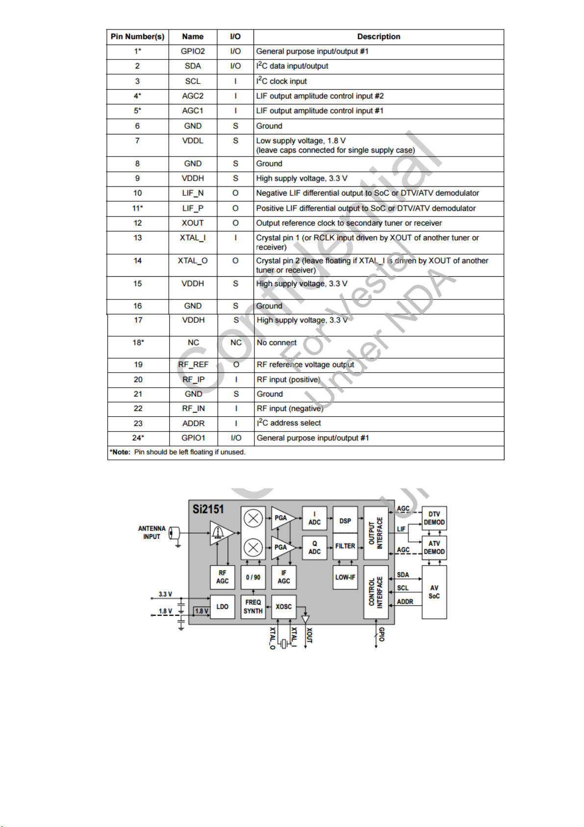
A.Digital and Analog TV Tuner: (Si2151 / U6) ...............................................................................................................3
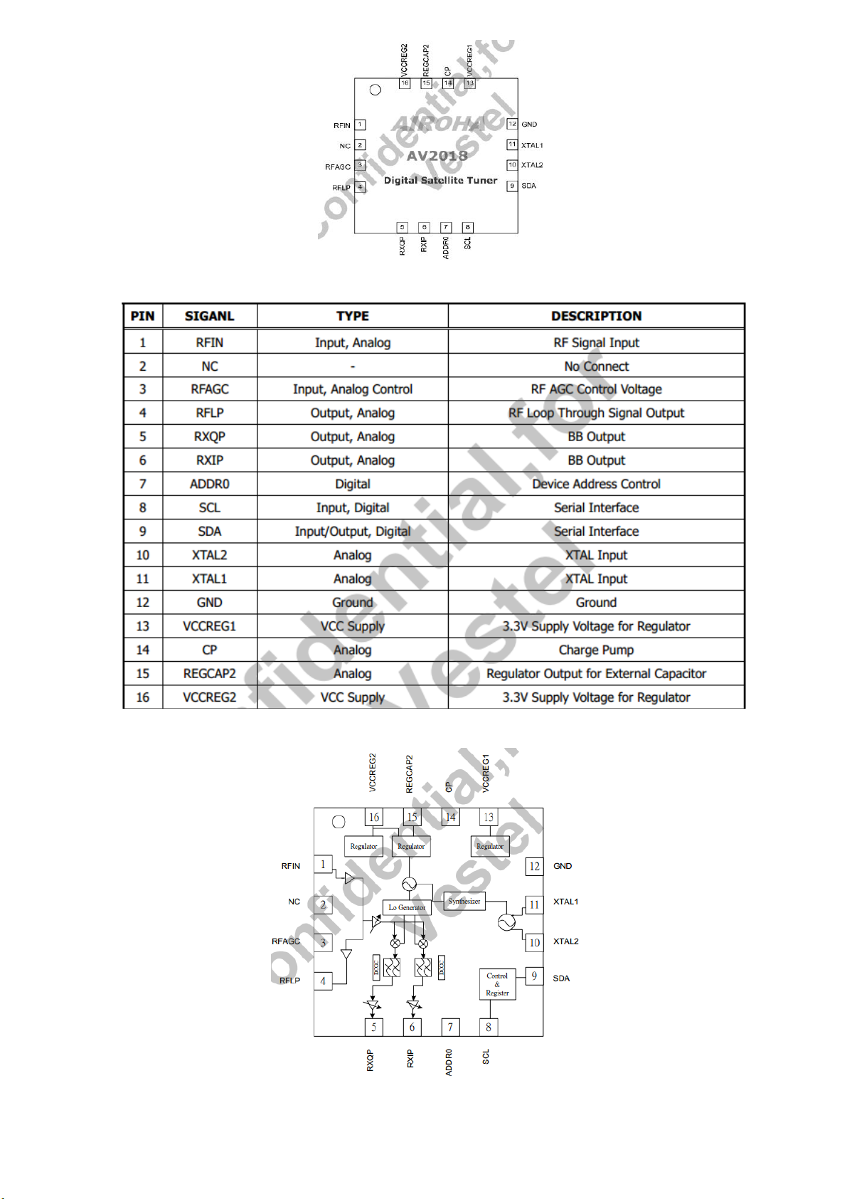
B. Digital Satellite Tuner (AV2018 / U27)....................................................................................................................... 5
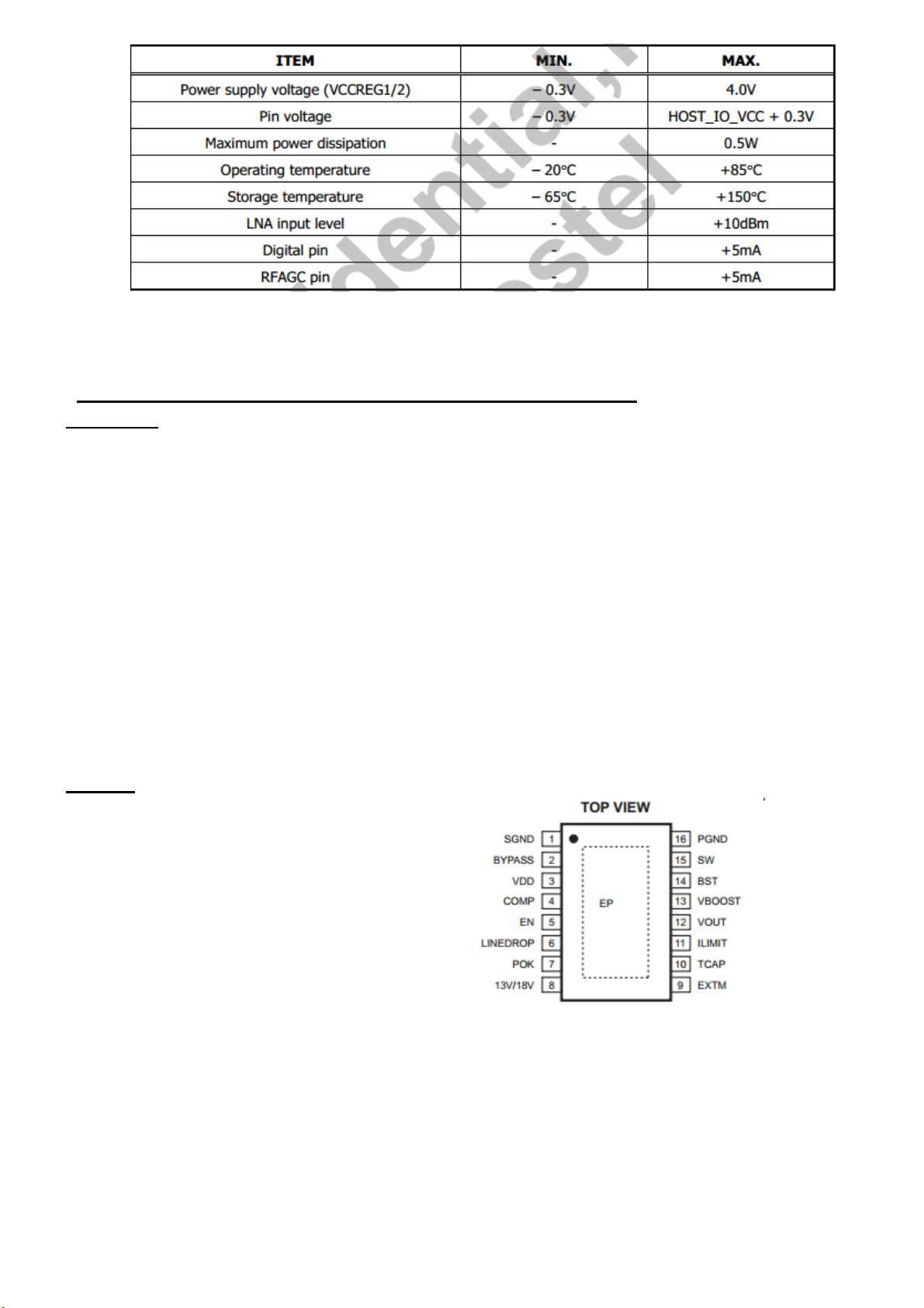
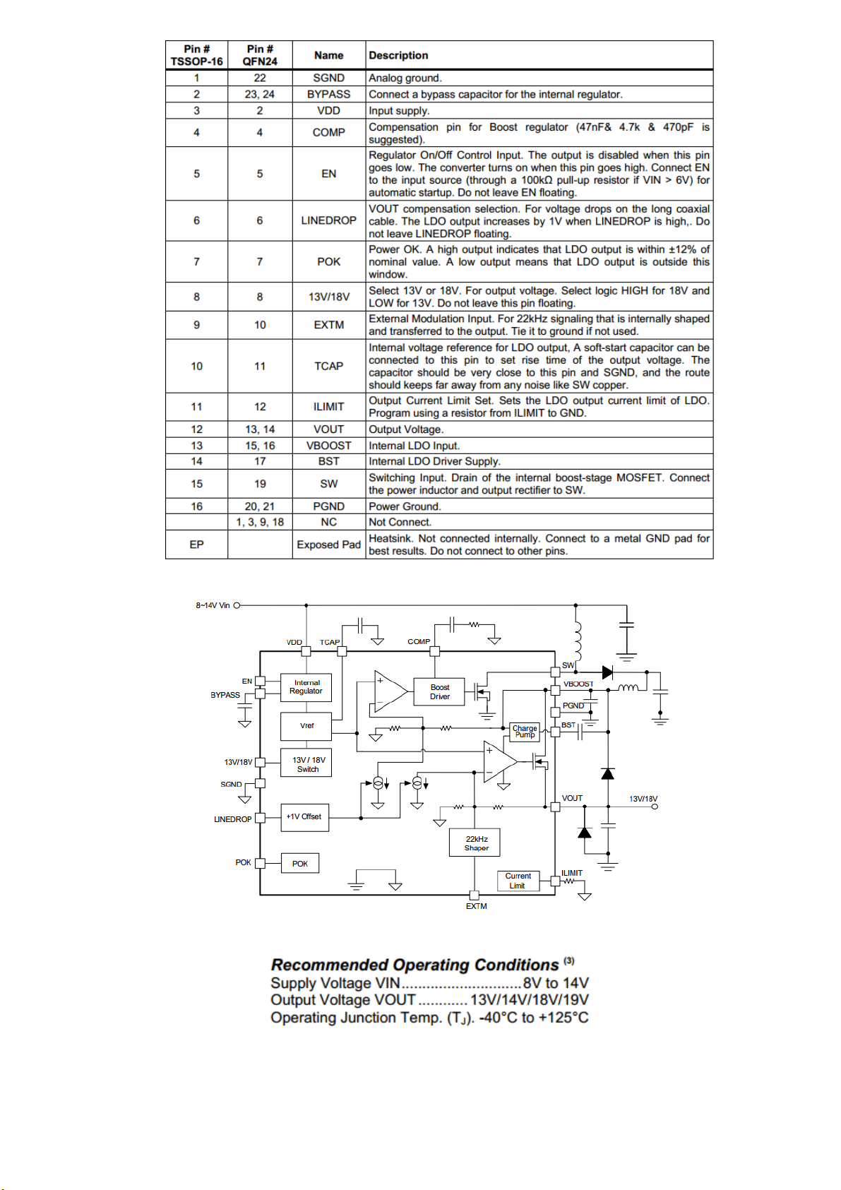
3. LNB SUPPLY AND CONTROL IC (MPS8126 / U26) ........................................................................................ 7
4. DEMODULATOR STAGE (Si2169 / U5)............................................................................................................. 9
5. AUDIO AMPLIFIER STAGES ........................................................................................................................... 13
A.MAIN AMPLIFIER (AD82587D / U13) (10W) ............................................................................................................13
B. SUBWOOFER AMPLIFIER (AD82586C / U14) (12 W)................................................................................................16
C. HEADPHONE AMPLIFIER (AD22657B / U23) ............................................................................................................ 18
D.SUBWOOFER PREAMPLIFIER (AD22657B / U22) ..................................................................................................... 20
E. SCART AUDIO AMPLIFIER (TL062 / U12) ..................................................................................................................21
6. POWER STAGE................................................................................................................................................... 23
A.NTGS3446 (Q47) ...................................................................................................................................................... 24
B. FDS4685 (Q41) ......................................................................................................................................................... 24
C. TPS54528 (U30)........................................................................................................................................................ 24
D.TPS54628 (U28)........................................................................................................................................................ 26
E. TPS54821 (U29-U35)................................................................................................................................................28
F. RT7278G (U44)......................................................................................................................................................... 30
G.APL5910 (U31-U32-U33).......................................................................................................................................... 32
H.LM1117 (U36) ..........................................................................................................................................................34
7. MICROCONTROLLER (MEDIATEK MT5827P / U1) ..................................................................................... 35
8. VIDEO BACK-END PROCESSOR (MSTAR – MST7410FE / U3) .................................................................. 47
9. 4Gb DDR3 SDRAM (K4B4G1646D / U7-U8-U9-U10-U11) ............................................................................. 50
10. 32Mb SPI FLASH (W25Q32FVSSIG / U4) ........................................................................................................ 52
11. EMMC MEMORY (MTFC16GAKAECN-2MWT / U24) .................................................................................. 55
12. USB INTERFACE................................................................................................................................................ 58
TPS2553 (U16-U17-U18-U19-U39) ..........................................................................................................................58
13. RESET IC (MAX809 / U41) ................................................................................................................................ 60
14. SOFTWARE UPDATE ........................................................................................................................................ 61
15. TROUBLESHOOTING........................................................................................................................................ 64
A.No Backlight Problem .............................................................................................................................................. 64
B. CI Module Problem ..................................................................................................................................................65
C. StayIng In Standby Mode .........................................................................................................................................66
D.IR Problem................................................................................................................................................................67

2
E. Keypad Touchpad Problems ....................................................................................................................................68
F. USB Problems........................................................................................................................................................... 68
G.No Sound Problem ...................................................................................................................................................69
H.Standby On/Off Problem .........................................................................................................................................70
İ. No Signal Problem....................................................................................................................................................70
16. GENERAL BLOCK DIAGRAM ......................................................................................................................... 73
1.INTRODUCTION
17MB300 main board is driven by Mediatek SOC. This IC is a single chip Android TV with built in digital
tuner solution that supports channel decoding, MPEG decoding, and media-center functionality enabled by a
high performance AV CODEC and CPU. This IC also supports 4K2K (UHD).
Key Features:
Worldwide multi-standard analog TV demodulator
ATSC/DVB-T/DVB-C demodulators
True 120Hz Full HD MJC
Powerful CPU core
D graphic support OpenGL ES 3.0, DirectX DX11
A transport de-multiplexer
A muti-standard video decoder (including VP9)
Rich format audio codec
H.264 encoder
HDMI 1.4a/2.0 receiver with 3D support
MHL 2.0 & Standby Charging
2D/3D converter
Ethernet MAC+PHY
Local dimming (LED backlight)
TCON
Panel overdrive control
four-link LVDS, mini-LVDS, V-by-one, EPI
Supported Peripherals are:
1 RF input VHF I, VHF III, UHF
1 Satellite input
1 Side AV (CVBS, R/L_Audio)
1 SCART socket(Common)
1 YPbPr / Back S-Video(Common)
1 PC input(Common)
4 HDMI input(2xHDMI1.4 and 2xHDMI2.0) (Common)
1 Common interface(Common)
1 Optic S/PDIF output(Common)
1 Stereo audio input for PC(Common)
1 Subwoofer output(Common)
1 Headphone(Common)
1x USB3.0 and 2xUSB2.0
1 Ethernet-RJ45

3
2.TUNER
A. DIGITAL AND ANALOG TV TUNER: (SI2151 / U6)
Description
The Si2151 is Silicon Labs' sixth-generation hybrid TV tuner supporting all worldwide terrestrial and cable
TV standards. Requiring no external balun, SAW filters, wirewound inductors or LNAs, the Si2151 offers the
lowest-cost BOM for a hybrid TV tuner. Also included are an integrated power-on reset circuit and an option
for single power supply operation. As with prior-generation Silicon Labs TV tuners, the Si2151 maintains very
high linearity and low noise to deliver superior picture quality and a higher number of received stations when
compared to other silicon tuners. The Si2151 offers increased immunity to WiFi and LTE interference,
eliminating the need for external filtering. For the best performance with next-generation digital TV standards,
such as DVB-T2/C2, the Si2151 delivers industry-leading phase noise performance.
Features
Worldwide hybrid TV tuner
-Analog TV: NTSC, PAL/SECAM
-Digital TV: ATSC/QAM, DVBT2/T/C2/C, ISDB-T/C, DTMB
-1.7 MHz, 6 MHz, 7 MHz, 8 MHz, and 10 MHz channel bandwidths
-42-1002 MHz frequency range
Industry-leading margin to A/74, NorDig, DTG, ARIB, EN55020, OpenCable™, DTMB
Lowest BOM for a hybrid TV tuner
-No balun, SAW filters, or external inductors required
-Increased ESD protection on 4pins
Best-in-class real-world reception
-Lowest phase noise
-High Wi-Fi and LTE immunity
Low power consumption
-3.3 V and 1.8 V power supplies
-Integrated 1.8 V LDO for 3.3 V single supply operation
Integrated power-on reset circuit
Standard CMOS process
3x3 mm, 24-pin QFN package
RoHS compliant
Figure 1: Pin Assignment

4
Table 1: Pin Description
Figure 2: Functional Block Diagram

5
Table 2: Recommended Operating Conditions
B. DIGITAL SATELLITE TUNER (AV2018 / U27)
Description
The AV2018 is a highly integrated silicon tuner for DVB-S2 standard. It integrates a synthesizer, crystal
oscillator, LDO, loop through path, and a direct conversion receiver including LNA, RF variable gain
amplifiers, Mixer, programmable channel filter, and PGA.
The low noise figure of the receiver and loop through path eliminates the need of an external LNA. The
integrated crystal oscillator can provide a reference clock for demodulator. The LDO supplies all the internal
blocks the only an external voltage source is required. The AV2018 requires only a small number of external
components, thus enables very competitive design.
The AV2018 implements an automatic gain control mechanism that only an analog control signal from the
demodulator is required to from a close-loop gain control. The mechanism will arrange the gain of the receiver
blocks to achieve best performance according to the control signal voltage. The embedded automatic calibration
mechanism provides precise control of channel filter bandwidth and DC offset, no additional calibration
procedure is required.
Features
Input RF Frequency: 950Mhz to 2150Mhz
Single +3.3V power Supply
Embedded LNA, Mixer, VCO, crystal oscillator, and LDO
Low Noise Figure: 5 dB, typical
Embedded DC offset Cancellation Circuit
Programmable channel filter with bandwith from 4MHz to 40MHz
Automatic gain control
Embedded RF signal loop through path
Single-ended I/Q interface
QFN3*3mm 16pin package

6
Figure 3: Pin Assigment
Table 3: Pin Description
Figure 4: Functional Block Diagram

7
Table4: Absolute Maximum Ratings
3.LNB SUPPLYAND CONTROL IC (MPS8126 / U26)
Description
The MP8126 is a voltage regulator designed to provide efficient, low-noise power to a satellite receiver’s RF
LNB (Low Noise Block) converter. It connects using a coaxial cable through a link that is compatible with the
European EUTELSAT specification (DiSEqC) 1.x that receives instructions from a dedicated controller.
The MP8126 integrates a current-mode boost regulator followed by a tracking linear regulator. The boost
regulator provides a clean and quiet power source that will not contaminate the lownoise RF signal as it is
down-converted to the receiver. The tracking linear regulator protects the output against overloads or shorts.
The MP8126 provides a number of features described in the DiSEqC, including voltage selection of
horizontal or vertical LNB polarization directions, and selectable VOUT compensation for substantial voltage
drops on long coaxial cable. In accordance with DiSEqC, the part can detect a 22kHz signal and output a
shaped signal.
The MP8126 is available in a thermally enhanced TSSOP16EP and 24-pin QFN (4X4mm) packages.
Features
DiSEqC 1.x Compatibility
Up to 550mA Output Current
Programmable Current Limit
8V-to-14V Input Voltage
Boost Converter with Internal Switch
Low-Noise LDO Output
Built-In 22kHz Signal Shaper
1V Line-Drop Compensator
Adjustable Soft-Start Time
POK Indicator
Figure 5: Pin Assignment
Short-Circuit Protection
Over-Temperature Protection
TSSOP16 Exposed Pad and 24-pin QFN (4X4mm) Packages

8
Table 5: Pin Description
Figure 6: Functional Block Diagram
Table 6: Recommended Operating Conditions

9
4.DEMODULATOR STAGE (SI2169 / U5)
Description
The Si2169 integrates DVB-T2, DVB-T, DVB-C, DVB-S and DVB-S2 digital demodulators into a single
advanced CMOS technology mixed-signal die for new generation terrestrial, cable, and satellite TV standards.
Leveraging Silicon Labs’ proven digital demodulation architecture, the Si2169 achieves excellent reception
performance for each media while significantly minimizing front-end design complexity, cost, and power
dissipation. Connecting the Si2169 to a terrestrial and cable hybrid TV tuner, such as Silicon Labs’ Si214x,
Si215x, and Si217x, results in a high performance and cost optimized TV front-end solution.
Features
Flexible tuner interface
-Accepts standard or lo IF input for DVB-T2/T/C
-ZIF for DCB-S2/S and DSS
DVB-T2 (ETSI EN 302 755)
-COFDM demodulator FEC (LDP/BCH) decoder
-NorDig Unified ver.2.2.1 and D-Book 7.0 compliant
-Supports single and multiple PLPs
-Supports SISO and MISO transmission
-Fully automatic acquisition
-Automatic L1 signaling parsing
-Short locking time
DVB-T (ETSI EN 300 744)
-COFDM demodulator and FEC decoder
-NorDig Unified 2.2.1, D-Book 7.0 compliant
-Supports all C.R.; G.I.; LP AND HP streams
DVB-C (ETSI EN 300 429/ITU J.83 Annex A/C)
-QAM demodulator end FEC decoder
-1 to 7.2 MSymbol/s
-C-Book compliant
DVB-S (ETSI EN 300 421)
-QPSK demodulator end FEC decoder
-1 to 45 MSymbol/s
DVB-S2 (ETSI EN 302 307 and TR102-376)
-QPSK/8PSK demodulator end FEC (LDPC/BCH) decoder
-Broadcast profile: CCM, 64800bit frame, single TS
-1 to 45 MSymbol/s
-Roll-off factors: 0.35 / 0.25 / 0.20
-DIRECTVTM AMC compatible
DIRECTVTM (DSS) compliant
DiSEqCTM 2.0 interface, Unicable support
DSP-base synchronization and demodulation control
-Embedded ROM/NVM-coded firmware avoids code download and allows immediate operation at
startup
-Supports firmware patch code downloads for if-field upgradeability

10
Lock, BER, PER and SND indicators
Fast scanning functionality for all media, including efficient blind scan for satelliye and cable
12-bit ADCs with indipendent IF and ZIF inputs for terrestrial/cable and satellite respectively ( 1 Vpp
differential inputs)
Power consumption: <550 mW in DVB-S2 modes; <450 mW in DVB-T2 modes; <200 mW in DVB-T
and DVB-C modes
Automatic spectreal inversion detection for all media
Clocks derived from 16-30 Mhz crystal using an on-chip oscillator or by connection to 4-30 Mhz tuner
reference clock.
Clock output to drive a secondary demodulator
Up to 4 multipurpose ports to control tuners’ AGC and tuner AGC freze
Two GPIOs
Master Ts outpu modes, parellel or serial
(with tri-state function)
Slave TS parallel output interfaces seamlessly to external controllers for USB2.0, PCI-E, etc. External
device polls data from on-chip FIFO via GPIF interface
I2C serial bus interfaces (master and host)
3.3 and 1.2 V power supplies
Minimal BOM using standard components
Ultra-compact QFN-48, 7x7 mm, Pb-free/RoHS-compliant package
Pin-to-pin compatible with Si2166-B/67-B and Si2168
For DVB-T2:
Bandwidth: 1.7, 5,6,7 or 8 Mhz (and extended bandwidth)
DVB-T2 versus DVB-T automatic detection
Carrier recovery: + 600 kHz
Timing recovery: + 200 ppm
Supports all DVB-T2 modulation parameters:
-All guard intervals, all FFT including extended bandwidth, all pilot patterns,
-All rotated and not-rotated constellations, all code rates and frame sizes.
Accepts up to 255 PLP(s) and outputs the data PLP + the common PLP on a single TS
FEF management with available output signal to freze tuner AGC during FEF
Advanced terrestrial channel equalizer
State-of-the-art impulsive noise protection algorithm
CPE compensation to counteract tuner phase noise
For DVB-T:
Bandwidth: 6, 7, 8 MHz. ACI filtering for 7 MHz channels enables use of a fixed 8 MHz IF filter
Carrier recovery: + 600 kHz
Timing recovery: + 200 ppm
Advanced terrestrial channel equalizer
State-ofoart impulsive noise protection algorithm
CPE compensation to counteract tuner phase noise
For DVB-C:
DFE equalizer spesific for cable network
Carrier recovery: + 11% of Symbol rate
Timing recovery: + 1000 ppm
For DVB-S/S2:
Programmable carrier range
Timing recovery: +1000 ppm

11
Figure 7: Pin Assignment

12
Table 7: Pin Description
Figure 8: Functional Block Diagram
Table 8: Recommended Operating Conditions

13
5.AUDIO AMPLIFIER STAGES
A. MAIN AMPLIFIER (AD82587D / U13) (10W)
Description
AD82587D is a digital audio amplifier capable of driving a pair of 8 ohm, 20W or a single 4 ohm, 40W
speaker, both which operate with play music at a 24V supply without external heat-sink or fan requirement.
Using I2C digital control interface, the user can control AD82587D’s input format selection, DRC (dynamic
range control), mute and volume control functions. AD82587D has many built-in protection circuits to
safeguard AD82587D from connection errors.
Features
16/18/20/24-bit input with I2S, Left-alignment and Right-alignment data format
PSNR & DR(A-weighting) Loudspeaker: 97dB (PSNR), 105dB (DR) @ 24V
Multiple sampling frequencies (Fs)
-32kHz / 44.1kHz / 48kHz and
-64kHz / 88.2kHz / 96kHz and
-128kHz/176.4kHz/192kHz
System clock = 64x, 128x, 256x, 384x, 512x, 768x,1024x Fs
-256x~1024x Fs for 32kHz / 44.1kHz / 48kHz
-128x~512x Fs for 64kHz / 88.2kHz / 96kHz
-64x~256x Fs for 128kHz /176.4kHz/192kHz
Supply voltage
-3.3V for digital circuit
-10V~26V for loudspeaker driver
Loudspeaker output power for Stereo@ 24V
-10W x 2ch into 8_ @ 0.16% THD+N
-15W x 2ch into 8_ @ 0.18% THD+N
-20W x 2ch into 8_ @ 0.24% THD+N
Loudspeaker output power for Mono@ 24V
-20W x 1ch into 4_ @ 0.17% THD+N
-30W x 1ch into 4_ @ 0.2% THD+N
-40W x 1ch into 4_ @ 0.24% THD+N
Sounds processing including:
-Volume control (+24dB~-103dB, 0.125dB/step)
-Dynamic range control
-Power clipping
-Channel mixing
-User programmed noise gate with hysteresis window
-DC-blocking high-pass filter
Anti-pop design
Short circuit and over-temperature protection
I2C control interface with selectable device address
Internal PLL
LV Under-voltage shutdown and HV Under-voltage detection

14
Power saving mode
Dynamic temperature control
Figure 9: Pin Assignment

15
Table 9: Pin Description
Figure 10: Functional Block Diagram

16
Table 10: Recommended Operating Conditions
B. SUBWOOFER AMPLIFIER (AD82586C / U14) (12 W)
Description
AD82586C is a digital audio amplifier capable of driving a pair of 8 ohm, 20W operating at 24V supply
without external heat-sink or fan requirement with play music.
AD82586C can provide advanced audio processing capabilities, such as volume control, 20 bands speaker
EQ, audio mixing, 3D surround and DRC (dynamic range control). These functions are fully programmable via
a simple I2C control interface.
Robust protection circuits are provided to protect AD82586C from damage due to accidental erroneous
operating condition. AD82586C is more tolerant to noise and PVT (Process, Voltage, and Temperature)
variation than the analog Class-AB or Class-D audio amplifier counterpart implemented by analog circuit
design. AD82586C is pop free during instantaneous power switch because of its built-in, robust anti-pop circuit.
Features
16/18/20/24-bits input with I2S, Left-alingment and Right-alingment data format
PSNR & DR (A-weighting) Loudspeaker: 99dB (PSNR), 104dB (DR) @24V
Multiple sampling frequencies (Fs)
-32kHz / 44.1kHz / 48kHz and
-64kHz / 88.2kHz / 96kHz and
-128kHz / 176.4kHz / 192kHz
System clock = 64x, 128x, 192x, 256x, 384x, 512x, 576x, 768x, 1024x Fs
-64x~1024x Fs for 32kHz / 44.1kHz / 48kHz
-64x~512x Fs for 64kHz / 88.2kHz / 96kHz
-64x~256x Fs for 128kHz / 176.4kHz / 192kHz
Supply voltage
-3.3V for digital circuit
-10V~26V for loudspeaker driver
Loudspeaker output power at 24V
-10W x 2CH into 8 ohm @0.17% THD+N for stereo
-20W x 2CH into 8 ohm @0.26% THD+N for stereo
Sound processing including:
-20 bands parametric speaker EQ
-Volume control (+24dB~-103dB, 0.125dB/step)
-Dynamic Range Control (DRC)
-Dual band DRC

17
-Power clipping
-3D surround sound
-Channel mixing
-Noise gate with hysteresis window
-Bass/Treble tone control
-DC-blocking high-pass filter
Anti-pop design
Short circuit and over-temperature protection
I2C control interface with selectable device address
Support hardware and software reset
Internal PLL
LV Under-Voltage shutdown and HV Under-Voltage detection
Power saving mode
Figure 11: Pin Assignment

18
Table 11: Pin Description
Figure 12: Functional Block Diagram
Table 12: Recommended Operating Conditions
C. HEADPHONE AMPLIFIER (AD22657B / U23)
Description
The AD22657B is a 2-Vrms cap-less stereo line driver. The device is ideal for single supply electronics.
Cap-less design can eliminate output dc-blocking capacitors for better low frequency response and save cost.

19
The AD22657B is capable of delivering 2-Vrms output into a 10k ohm load with 3.3V supply. The gain
settings can be set by users from 1V/V to 10V/V externally. The AD22657B has under voltage protection to
prevent POP noise. Build-in shutdown control and de-pop control sequence also help AD22657B to be a pop-
less device.
The AD22657B is available in a 10-pin MSOP package.
Features
Operation Voltage: 3V to 3.6V
Cap-less Output
-Eliminates Output Capacitors
-Improves Low Frequency Response
-Reduces POP/Clicks
Low Noise and THD
- Typical SNR 107dB
- Typical Vn 7uVrms
- Typical THD+N < 0.02%
Maximum Output Voltage Swing into 2.5k Load
-2Vrms at 3.3V Supply Voltage
Single-ended Input
External Gain Setting from 1V/V to 10V/V
Fast Start-up Time: 0.5ms
Integrated De-Pop Control
External Under Voltage Protection
Thermal Protection
Less External Components Required
+/-8kV IEC ESD Protection at line outputs
Figure 13: Pin Assignment
This manual suits for next models
1
Table of contents
Other VESTEL TV manuals

VESTEL
VESTEL MB27 User manual

VESTEL
VESTEL TERRANOVA SMART 55PF9116 User manual

VESTEL
VESTEL 43U9402 User manual

VESTEL
VESTEL 16VH3021 User manual

VESTEL
VESTEL 17MB15 User manual

VESTEL
VESTEL 17MB08P User manual

VESTEL
VESTEL 22F8500P User manual

VESTEL
VESTEL 43UA8900 User manual

VESTEL
VESTEL 17MB18 User manual

VESTEL
VESTEL MB82S User manual

VESTEL
VESTEL MB185 IDTV User manual

VESTEL
VESTEL 24HA9520M User manual

VESTEL
VESTEL 55PF9060 User manual

VESTEL
VESTEL 65Q9700TT User manual

VESTEL
VESTEL 17MB18P-3 User manual

VESTEL
VESTEL 49F9500 User manual

VESTEL
VESTEL 2310 User manual

VESTEL
VESTEL 65UA9630 User manual

VESTEL
VESTEL 42PF7017B User manual

VESTEL
VESTEL 65UA9630 User manual