VESTEL 17MB08P User manual

26” TFT
SERVICE MANUAL
(17MB08P)
RELEASE DATE: 04.03.2005
PREPARED BY: VESTEL ELECTRONICS

THIS PAGE IS INTENTIONALLY LEFT BLANK

i
26” TFT TV Service Manual 04/03/2005
TABLE OF CONTENTS
1. INTRODUCTION ...................................................................................................................................... 1
2. TUNER...................................................................................................................................................... 1
3. IF PART (TDA9886) ................................................................................................................................. 1
4. MULTI STANDARD SOUND PROCESSOR ............................................................................................ 2
5. VIDEO SWITCH TEA6415 ....................................................................................................................... 2
6. AUDIO AMPLIFIER STAGE WITH TPA3002D2 ...................................................................................... 2
7. POWER .................................................................................................................................................... 2
8. MICROCONTROLLER SDA55XX............................................................................................................ 3
8.1. General Features............................................................................................................................... 3
8.2. External Crystal and Programmable Clock Speed............................................................................ 3
8.3. Microcontroller Features.................................................................................................................... 3
8.4. Memory.............................................................................................................................................. 3
8.5. Display Features................................................................................................................................ 3
8.6. ROM Characters................................................................................................................................ 3
8.7. Acquisition Features .......................................................................................................................... 4
8.8. Ports .................................................................................................................................................. 4
9. SERIAL ACCESS CMOS 16K (2048*8) EEPROM ST24C16 .................................................................. 4
10. CLASS AB STEREO HEADPHONE DRIVER TDA1308 .........................................................................4
11. SAW FILTERS.......................................................................................................................................... 4
12. IC DESCRIPTIONS AND INTERNAL BLOCK DIAGRAM ....................................................................... 5
12.1. LM1117.............................................................................................................................................. 5
12.1.1. General Description................................................................................................................. 5
12.1.2. Features .................................................................................................................................... 5
12.1.3. Applications.............................................................................................................................. 5
12.1.4. Connection Diagrams.............................................................................................................. 5
12.2. LM2576.............................................................................................................................................. 6
12.2.1. General Description................................................................................................................. 6
12.2.2. Features .................................................................................................................................... 6
12.2.3. Pin description ......................................................................................................................... 6
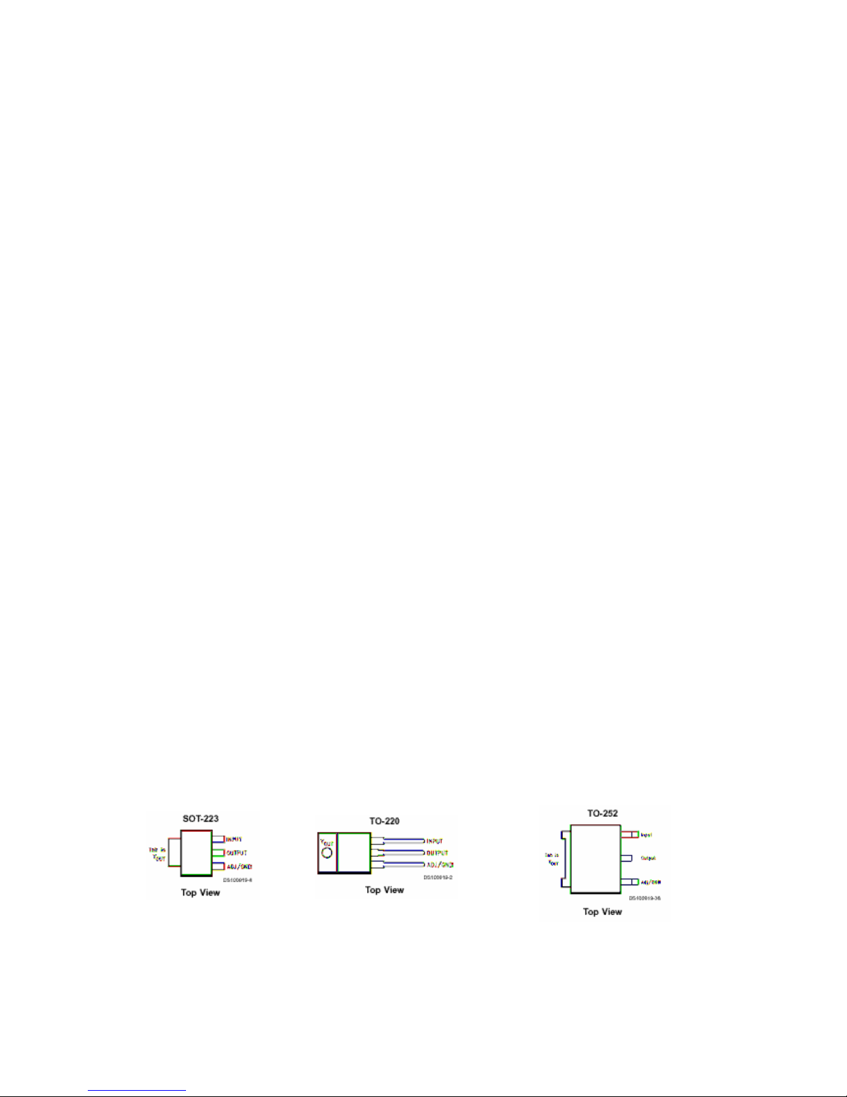
12.3. LM317T ............................................................................................................................................. 7
12.3.1. Description................................................................................................................................7
12.3.2. Features .................................................................................................................................... 7
12.4. ST24LC21 ......................................................................................................................................... 8
12.4.1. Description................................................................................................................................8
12.4.2. Features .................................................................................................................................... 8
12.4.3. Pin connections........................................................................................................................ 8
12.5. TEA5114A ......................................................................................................................................... 9
12.5.1. General description ................................................................................................................. 9
12.5.2. Features .................................................................................................................................... 9
12.5.3. Pin Connections....................................................................................................................... 9
12.6. TEA6415.......................................................................................................................................... 10
12.6.1. General description ............................................................................................................... 10
12.6.2. Features .................................................................................................................................. 10
12.6.3. Pinning.................................................................................................................................... 10
12.7. VPC3230D....................................................................................................................................... 11
12.7.1. General Description............................................................................................................... 11
12.7.2. Pin Connections and Short Descriptions............................................................................ 11
12.8. SDA55XX (SDA5550)...................................................................................................................... 13
12.8.1. General description ............................................................................................................... 13
12.9. TPA3003D2 ..................................................................................................................................... 14
12.9.1. General Description............................................................................................................... 14
12.9.2. Features .................................................................................................................................. 14
12.9.3. Pin Connection....................................................................................................................... 14
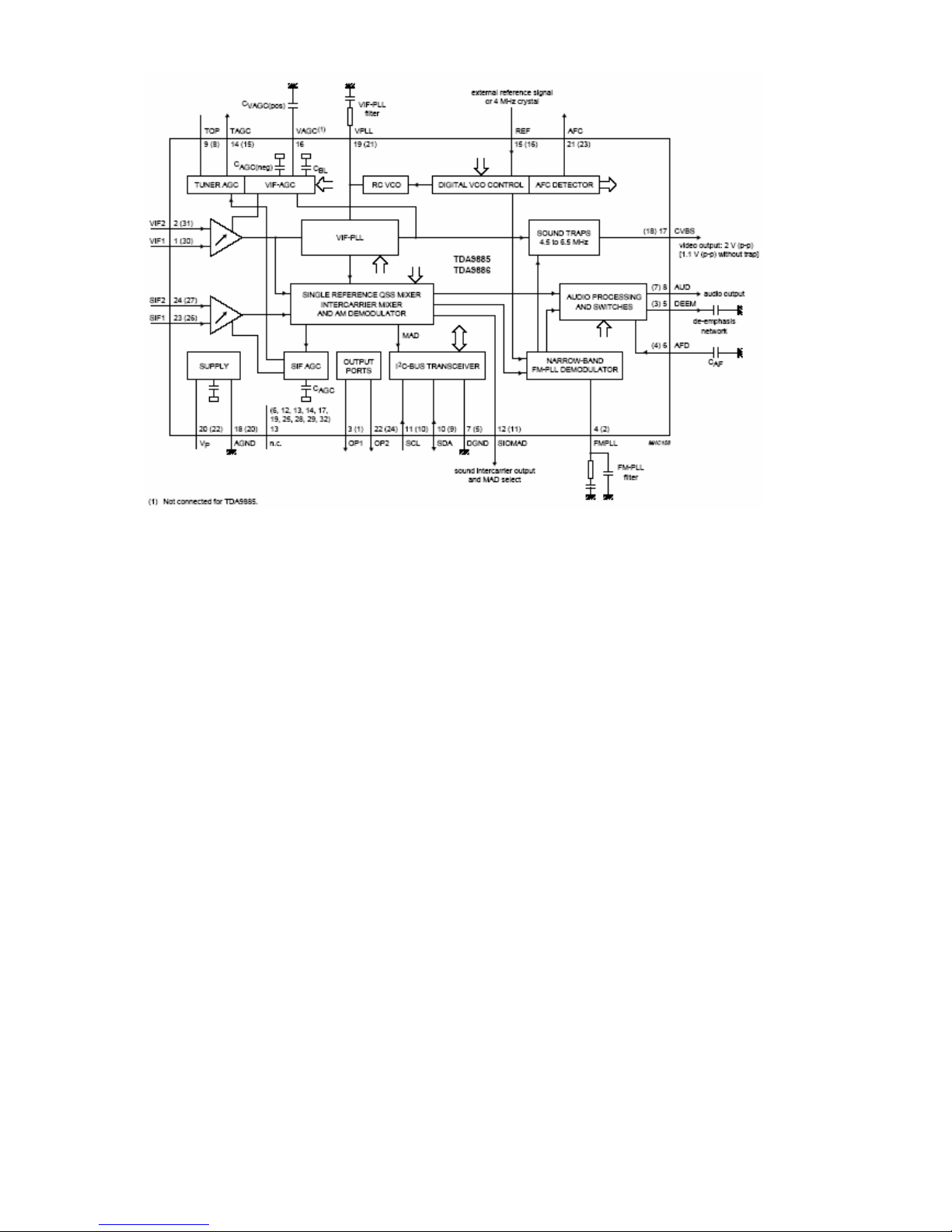
12.10. TDA9885/86 .................................................................................................................................... 15
12.10.1. General description ............................................................................................................... 15
12.10.2. Features .................................................................................................................................. 15
12.10.3. Pinning.................................................................................................................................... 15

ii
26” TFT TV Service Manual 04/03/2005
12.11. TDA1308 ......................................................................................................................................... 16
12.11.1. General Description............................................................................................................... 16
12.11.2. Features .................................................................................................................................. 16
12.11.3. Pinning.................................................................................................................................... 16
12.12. PI5V330........................................................................................................................................... 17
12.12.1. General description ............................................................................................................... 17
12.12.2. Features .................................................................................................................................. 17
12.12.3. Pin Descriptions..................................................................................................................... 17
12.13. GM6015........................................................................................................................................... 18
12.13.1. General description ............................................................................................................... 18
12.13.2. Features .................................................................................................................................. 18
12.14. AD9883A ......................................................................................................................................... 19
12.14.1. General description ............................................................................................................... 19
12.14.2. Features .................................................................................................................................. 19
12.14.3. Pin Descriptions..................................................................................................................... 19
12.15. MC141585 ....................................................................................................................................... 22
12.15.1. General description ............................................................................................................... 22
12.15.2. Features .................................................................................................................................. 22
12.15.3. Pin Description....................................................................................................................... 22
12.16. MC34063 ......................................................................................................................................... 24
12.16.1. Description.............................................................................................................................. 24
12.16.2. Features .................................................................................................................................. 24
12.16.3. Pin connections...................................................................................................................... 24
12.17. MSP34X0G (MSP3410G) ............................................................................................................... 25
12.17.1. Introduction ............................................................................................................................ 25
12.17.2. Features .................................................................................................................................. 25
12.17.3. Pin connections...................................................................................................................... 26
12.18. DS90C385 ....................................................................................................................................... 28
12.18.1. General Description............................................................................................................... 28
12.18.2. Features .................................................................................................................................. 28
12.18.3. Pinning.................................................................................................................................... 28
12.19. NDS8947 ......................................................................................................................................... 29
12.19.1. General Description............................................................................................................... 29
12.19.2. Features .................................................................................................................................. 29
13. SERVICE MENU SETTINGS ................................................................................................................. 30
13.1. ADJUST MENU SETTINGS............................................................................................................30
13.2. OPTIONS MENU SETTINGS..........................................................................................................31
13.3. APS WSS TEST MENU .................................................................................................................. 36
14. BLOCK DIAGRAM.................................................................................................................................. 37
15. CIRCUIT DIAGRAMS............................................................................................................................. 38

1
26” TFT TV Service Manual 04/03/2005
1. INTRODUCTION
26” TFT TV is a progressive TV control system with built-in de-interlacer and scaler. It uses a 1280*768
panel with 15:9 aspect ratio.The TV is capable of operation in PAL, SECAM, NTSC (playback) colour
standards and multiple transmission standards as B/G, D/K, I/I’, and L/L’ including German and NICAM
stereo. Sound system output is supplying 2x8W (10%THD) for stereo 8speakers. The chassis is
equipped with many inputs and outputs allowing it to be used as a center of a media system.
It supports following peripherals:
2 SCART’s with all of them supporting full SCART features including RGB input
1 AV input. (CVBS+ Stereo Audio)
1 SVHS iput
1 Stereo Headphone output
1 D-Sub 15 PC input
1 DVI input (Optional)
1 Audio line out
1 Stereo audio input for PC/DVI
2. TUNER
As the thickness of the TV set has a limit, a horizontal mounted tuner is used in the product, which is
suitable for CCIR systems B/G, H, L, L’, I/I’, and D/K. The tuning is available through the digitally controlled
I2C bus (PLL). Below you will find info on the Tuner in use.
General description of UV1316:
The UV1316 tuner belongs to the UV 1300 family of tuners, which are designed to meet a wide range of
applications. It is a combined VHF, UHF tuner suitable for CCIR systems B/G, H, L, L’, I and I’. The low IF
output impedance has been designed for direct drive of a wide variety of SAW filters with sufficient
suppression of triple transient.
Features of UV1316:
1. Member of the UV1300 family small sized UHF/VHF tuners
2. Systems CCIR: B/G, H, L, L’, I and I’; OIRT: D/K
3. Digitally controlled (PLL) tuning via I2C-bus
4. Off-air channels, S-cable channels and Hyper band
5. Compact size
6. Complies to “CENELEC EN55020” and “EN55013”
Pinning:
1. Gain control voltage (AGC) : 4.0V, Max: 4.5V
2. Tuning voltage
3. I²C-bus address select : Max: 5.5V
4. I²C-bus serial clock : Min:-0.3V, Max: 5.5V
5. I²C-bus serial data : Min:-0.3V, Max: 5.5V
6. Not connected
7. PLL supply voltage : 5.0V, Min: 4.75V, Max: 5.5V
8. ADC input
9. Tuner supply voltage : 33V, Min: 30V, Max: 35V
10. Symmetrical IF output 1
11. Symmetrical IF output 2
3. IF PART (TDA9886)
The TDA9886 is an alignment-free multistandard (PAL, SECAM and NTSC) vision and sound IF signal
PLL demodulator for positive and negative modulation, including sound AM and FM processing.
The following figure shows the simplified block diagram of the integrated circuit.
The integrated circuit comprises the following functional blocks:
VIF amplifier, Tuner and VIF-AGC, VIF-AGC detector, Frequency Phase-Locked Loop (FPLL) detector, VCO
and divider, Digital acquisition help and AFC, Video demodulator and amplifier, Sound carrier trap, SIF amplifier,
SIF-AGC detector, Single reference QSS mixer, AM demodulator, FM demodulator and acquisition help, Audio
amplifier and mute time constant, I²C-bus transceivers and MAD (module address), Internal voltage stabilizer.
Table of contents
Other VESTEL TV manuals

VESTEL
VESTEL 65Q9500TE User manual

VESTEL
VESTEL 2310 User manual

VESTEL
VESTEL 65Q9700TT User manual

VESTEL
VESTEL 43U9402 User manual

VESTEL
VESTEL 17MB18P-3 User manual

VESTEL
VESTEL TERRANOVA SMART 55PF9116 User manual

VESTEL
VESTEL 55ua8900 User manual

VESTEL
VESTEL MB82S User manual

VESTEL
VESTEL 16VH3021 User manual

VESTEL
VESTEL MB27 User manual

VESTEL
VESTEL 17MB18 User manual

VESTEL
VESTEL 32PF8011 User manual

VESTEL
VESTEL 17MB15 User manual

VESTEL
VESTEL 65UA9630 User manual

VESTEL
VESTEL 22F8500P User manual

VESTEL
VESTEL 43UA8900 User manual

VESTEL
VESTEL 65UA9630 User manual

VESTEL
VESTEL 42PF7017B User manual

VESTEL
VESTEL 17MB12 User manual

VESTEL
VESTEL 55PF9060 User manual