Vestil E-TUG-HD Series User manual

E-TUG-HD, Manual
Copyright 2021 Vestil Manufacturing Corp. Page 1 of 15
E-TUG-HD SERIES ELECTRIC POWERED TUGGER
OPERATION AND MAINTENANCE MANUAL
Receiving instructions:
After delivery, IMMEDIATELY remove the packaging from the product in a manner that preserves the
packaging and maintains the orientation of the product in the packaging; then inspect the product closely to
determine whether it sustained damage during transport. If damage is discovered during the inspection,
immediately record a complete description of the damage on the bill of lading. If the product is
undamaged, discard the packaging.
NOTES:
1) Compliance with laws, regulations, codes, and non-voluntary standards enforced in the location where
the product is used is exclusively the responsibility of the owner/end-user.
2) VESTIL is not liable for any injury or property damage that occurs as a consequence of failing to apply either:
a) Instructions in this manual; or b) Information provided on labels affixed to the product. Neither is Vestil
responsible for any consequential damages sustained as a result of failing to exercise sound judgment
while assembling, installing, using or maintaining this product.
TABLE OF CONTENTS PAGE TABLE OF FIGURES PAGE
Safety Principles 2
Product Introduction 2
Safety Guidelines 3
Removing EPT from Pallet 3
Functions Tests 4
6
Lifting & Transporting
Loads Batteries & Charger 6 - 7
Troubleshooting 8 - 11
4
12 - 13
15
VESTIL MANUFACTURING CORP.
2999 North Wayne Street, P.O. Box 507, Angola, IN 46703
Telephone: (260) 665-7586 -or- Toll Free (800) 348-0868
Fax: (260) 665-1339
www.vestilmfg.com e-mail: [email protected]m
FIG. 1 Function Controls, Gauges, & Safety Features
Maintenance &
Inspections MarkingsWa
Warranty
14

Copyright 2021 Vestil Manufacturing Corp. Page 2 of 15
PRODUCT INTRODUCTION
Specifications appear in the table below:
Vestil Manufacturing Corp. created this manual to acquaint owners and users of our electric pallet trucks
with safe operation and maintenance procedures. Employers are responsible for instructing employees to
use the product properly. Employees and any other persons, who might foreseeably use, repair,
or perform maintenance on the E-TUG must read and understand every instruction BEFORE using the
device. Cart operators should have access to the manual at all times and should review the directions
before each use. Contact Vestil for answers to any question you have after reading the entire manual.
Although Vestil diligently strives to identify foreseeable hazardous situations, this manual cannot address
every conceivable danger. The end-user is ultimately responsible for exercising sound judgment at all times.
SAFETY PRINCIPLES
We offer four types of electric powered tuggers (E-TUG-HD): 10,000 pound (~4,536kg),7,000 pound
(~3,175kg), 5,000 pound (~2,267kg) & 3,000 pound (~1,360kg) capacity models. Each unit conforms to the
generalized specifications disclosed in this manual and fulfills our demanding standards for quality, safety and
durability.
Vestil Manufacturing Corp. recognizes the critical importance of workplace safety. Each person who might
participate in operation or maintenance of the product must read this manual. Read the entire manual and fully
understand the directions BEFORE using or performing maintenance on the cart. If you do not
understand an instruction, contact Vestil for clarification. Failure to adhere to the directions in this
manual might lead to serious personal injury or even death.
Vestil is not liable for any injury or property damage that occurs as a consequence of failing to apply the safe
operation and maintenance procedures explained in this manual or that appear on labels affixed to the product.
Furthermore, failure to exercise good judgment and common sense may result in property damage, serious
personal injury, or death, and also are not the responsibility of Vestil.
This manual applies the hazard identification methods suggested for instruction manuals by the American
National Standards Institute (ANSI). In accordance with ANSI guidelines for hazard identification language, this
manual classifies personal injury risks and situations that could lead to property damage with SIGNAL WORDS.
These signal words announce an associated safety message. The reader must understand that the signal word
chosen indicates the seriousness of that hazard according to the following convention:
Identifies a hazardous situation which, if not avoided, WILL result in DEATH or SERIOUS
INJURY. Use of this signal word is limited to the most extreme situations.
Identifies a hazardous situation which, if not avoided, COULD result in DEATH or
SERIOUS INJURY.
Indicates a hazardous situation which, if not avoided, COULD result in MINOR or
MODERATE injury.
Identifies practices not related to personal injury, such as operation that could damage the cart.
No safety alert symbol (equilateral triangle enclosing an exclamation point) accompanies this
signal word.
Thank you for purchasing Electric Tugger (“E-TUG-HD,” “Electric Powered
Tugger,” “truck,” or “unit”) offered by Vestil Manufacturing Corporation (“Vestil”). Our
Electric Tuggers are durable, high-quality products that combine safety features and
low-maintenance mechanisms. Despite the product’s relatively simple mechanics, all
personnel must familiarize themselves with the safe operation instructions provided in
this manual.
E-TUG-HD, Manual

E-TUG-HD, Manual
Copyright 2021 Vestil Manufacturing Corp. Page 3 of 15
SAFETY GUIDELINES
Failure to read and understand the instructions included in this manual before using or servicing
the pallet truck constitutes misuse of the product. Study the entire manual before you use the tugger
for the first time and before each subsequent use. Read the manual to refresh your understanding of the safe
use and maintenance procedures. If questions remain after you finish reading the manual, contact Vestil for
answers. DO NOT attempt to resolve any problem with the tugger unless you are certain that it will be safe to use
afterwards.
To decrease the risk of electrocution:
DO NOT contact or operate the tugger close to electrified wires or other sources of electricity;
Before operating the E-TUG-HD , always inspect the area where you will use it.
Improper use might result in serious personal injuries to the operator and/or bystanders. To
minimize the possibility of injury, ALL persons who might operate, perform maintenance on, or service the E-
TUG-HD must read, understand and apply the following instructions:
DO NOT operate the E-TUG -HDunless and until you are:
1. Trained to use the machine; AND
2. Certified as a trained operator by your employer in accordance with U.S. OSHA regulations (29 CFR
§1910.178) and any standards incorporated by reference (e.g. ANSI/ITSDF B56.1-2005).
DO NOT attempt to lift or transport loads that exceed the rated capacity.
Inspect the machine before each use; DO NOT use the tugger unless it is in normal condition. Normal operating
condition exists if the tugger passes the inspection and functions tests.
DO NOT use the unit until you read and understand the entire owner’s manual. Review the manual before
each use AND before performing maintenance on the device.
DO NOT use the E-TUG-HD if the load-supporting elements sustain any structural damage. Structural elements
include, but are not limited to, the forks, carriage, and wheels. If structural damage is present, immediately
tag the unit “Out of Service” and inform maintenance personnel of the problem.
DO NOT use the E-TUG-HD if it makes unusual noises during operation.
DO NOT allow people to use tugger as rider.
DO NOT attempt to pull an unevenly distributed load. Always center and evenly distribute the load before pulling.
DO NOT operate the E-TUG-HD on surfaces (ramps or grades).
DO NOT leave the E-TUG-HD unattended while it supports a load. Completely disengage the load
from tugger.
DO NOT modify the tugger without first receiving written authorization from Vestil. Unauthorized
modifications may make the E-TUG-HD unsafe to use.
To maximize the service life of the tugger and to prevent damage:
Always store the machine in a secure, dry location where it will not interfere with traffic or other activities.
Maintain the product as suggested in “Maintenance & Inspections”.
REMOVING THE Narrow mast Stacker FROM THE SHIPPING PALLET:
Narrow Mast stacker is shipped in ready-to-use condition. However, it must first be removed from the shipping
pallet before it can be used for the first time.
DO NOT attempt to pull the tugger off of the pallet; it might tip over and cause bodily injuries or
property damage. To minimize the risk of injury to yourself or other persons, perform the following steps to
remove the machine from the shipping pallet:
1. Remove all packing material.
2. Inform all personnel not participating in the unpacking process to clear the area.
3. Lift the E-TUG off of the pallet using a hoist or a with a capacity of at least 2,000 pounds. Always apply
the proper hoisting procedure or forklift operation practices you learned during your training program.

Copyright 2021 Vestil Manufacturing Corp. Page 4 of 15
EMERGENCY STOP (“E-STOP”) BUTTON:
Press the E-stop button to
immediately interrupt all powered
functions. Use the E-stop during
operation if the ddrive (forward and
reverse) functions do not respond
normally to operator commands.
Use The E-Stop as a service brake to
secure the E-TUG-HD when parked
FIG. 1: Function Controls, Gauges, and Safety Features
BATTERY CHARGE GAUGE:
The battery charge gauge
indicates the status of the battery.
It is located on top of the main
body and to the center of the
machine cover. As the battery
discharges, display line shifts from
right to left.
Always check the gauge before
using the device; make sure that
the battery is charged before using
the tugger.
BELLY SWITCH:
The belly switch protects the operator from injury
while driving the EPT in reverse. When pressed, the
truck will change direction, i.e. move forward, for
approximately 3 seconds; after 3 seconds it will stop
completely. If the belly switch becomes jammed or
stuck, the stacker will move forward (away from the
operator) for at most 3 seconds; the control circuit will
remain disabled until reset.
To reset the circuit, either raise the handle to the
fully vertical position (or simply release the
handle), or press it downwards to the fully
horizontal position.
MOVEMENT CONTROLLERS:
To drive the E-TUG in the
forward direction, rotate the
movement control forward with
your thumbs as indicated by the
solid arrow superimposed on
photograph below. To move the
pallet truck in reverse, rotate
the
control wheel in the opposite
direction, which is shown with a
dashed arrow.
The degree of rotation determines the speed of
movement, so the farther you press the wheel in
either direction, the faster the E-TUG-HD will travel,
up to a maximum speed of ~3.7mph when unloaded
or ~2.8 mph when loaded to capacity. Simply by
releasing the movement control, the E-TUG-HD will
decelerate to a complete stop.
Handle
slow/fast speed switch
E-TUG-HD, Manual
Belly Switch
(Emergency Stop)
Movement Controllers
("Butterfly" Switches)

E-TUG-HD, Manual
Copyright 2021 Vestil Manufacturing Corp. Page 5 of 15
USE INSTRUCTIONS:
1. Determine Condition of Floor or Other Supporting Surface: Inspect the floor or other surfaces prior to use.
The supporting surface must be smooth and dry so choose a route that avoids obstacles, spills, and surface
damage.
Casters might become stuck in gaps or cracks in the surface, which could cause the tugger
to stop suddenly. A sudden stop can cause the load to shift and the load and truck might tip over.
2. Inspect the Tugger & Perform a Functions Test:
Inspection Prior to Use:
ALWAYS inspect the unit before you use it. Begin the inspection by removing all debris found on the surface
and housing, and then:
DO NOT use the tugger if you discover any damage or abnormalities. Tag the unit “Out-of-
Service” and report the problem[s] to authorized maintenance personnel.
Functions Test:
Verify that the unit works properly. Drive the tugger to a location where the following tests can be performed
without contacting overhead obstructions or items on the ground:
1. DDrive the tugger in reverse at low speed and while driving press the belly switch. Tugger should immidiately
drive in the opposite direction for ~ 3 seconds and then stop. Reset the control yoke.
2. Drive the tugger in both forward and reverse directions for a few seconds.
3. Test the hornn.
4.
Only use the tugger if all mechanisms function normally. If [a] malfunctions occurred, park the
tugger in a safe location, tag it “Out-of-Service” and then report the malfunctions to maintenance personnel.
Operation:
Step 1: Turn on the power. Pull the red E-stop button up.
Verify that the control yoke automatically returns to the vertical position when released.
Step 3: Set the speed to slow or fast by pressing slow/fast button
Step 2: Pull the red E-Stop button up to disengage the service brake.
NOTE: The E-TUG-HD uses magnetic brakes, which engage
when the throttled is turned forward/reverse.
Step 4: Rotate the movement control wheel in the appropriate direction to move either forward or in
reverse. [See “Movement Controls” text box and the corresponding photo on p. 4]

E-TUG-HD, Manual
Copyright 2021 Vestil Manufacturing Corp. Page 6 of 15
Lifting and Transporting Loads:
DO NOT operate the tugger until you read AND understand every instruction. If you do not understand
an instruction, contact Vestil for clarification. To reduce the possibility of sustaining or causing serious personal
injuries, ALWAYS:
1. Make sure that all other persons clear the area while you use the E-TUG.
2. Apply the fork truck operation and lifting practices learned during your operator training, and applied by your
employer. Follow the instructions below ONLY to the extent that they do not disagree with the operating practices
required by your employer.
Make sure that the net weight to be pulled does not exceed the rated load (capacity) of your tugger;
3. Review the safety guidelines on p. 3 before each use:
Apply proper pulling techniques ;
Ask a coworker to help you to hook the load to the tugger.
4. “Operator” means a person, who is trained and authorized to use a manually propelled high lift device. ONLY
persons who have successfully completed a training program, like the courses outlined on p.
4-5 of B56.10-2006, should operate the E-TUG. Safe operation requires operators to:
Develop safe working habits and a process for identifying hazards that exist or might be encountered during
operation;
Conduct thorough inspections of the usage area to identify unusual/hazardous conditions. Walk the path you will
use to transport loads with the tugger before hand. Do not use the tugger if the floor (or other supporting
surface) is uneven or damaged or cannot support the combined weight of the tugger and the load.
Make sure that the tugger has been inspected as recommended in the “Inspections & Maintenance” section of this
manual . Use the lifter ONLY IF it is deemed safe to use by designated inspection personnel.
To engage a trolley/platform truck, push the unit to a position in front of the intended load. Before engaging the load,
confirm that the hitch will fit to trolley/platform truck. Slowly move the unit to allow the hitch to slide into the trolley or
platform truck . Confirm that the net weight of the load do not exceed the capacity of the Tugger.
Hook the trolley/platform truck to tugger. Drive the tugger in reverse position with turning the directional knob
in reverse position.
To release the load, stop tugger in the desired location; disengage the tugger from trolley/platform truck;
and then slowly pull the tugger backward until hitch is completely out of the hook.
Batteryand Charger:
The charger allows electrical current to flow from
a wall socket through the battery. While operating the charger,
contact with water (rain, snow, etc.) could result in electric
shock or electrocution. Do NOT recharge the battery if the
SLNM is outdoors. Only recharge the battery indoors.
Turn off your E-TUG-HD:
Push E-stop to turn off the E-TUG-HD
Plug the charger’s AC cord into an 115VAC power source: The
AC cord is attached to the lower mast
E-Stop button

E-TUG-HD, Manual
Copyright 2021 Vestil Manufacturing Corp. Page 7 of 15
A proper storage location is one where the unusedtugger will not:
1. Interfere with or obstruct traffic or other operations;
2. Be exposed to corrosive chemicals or water, either as a consequence of weather or of worksite
conditions.

E-TUG-HD, Manual
Copyright 2021 Vestil Manufacturing Corp. Page 8 of 15
TROUBLESHOOTING:
Before performing any corrective action described in the following table, block the drive
wheel off of the ground.
Contact Vestil for problems at time of installation, or for any problems not addressed below.
Problem: Possible cause(s): Action:
Unit does not respond to
movement controls (does not
move either forward or in
reverse).
Battery voltage low (battery
charge lower than 17 Volts)
Problem with motor controller
(check for LED flash code on
side of controller)
Fuse blown
Charge batteries.
Bad batteries; load test batteries
and replace if necessary.
Consult diagnostics page on
controller Troubleshooting Chart;
or Refer to electrical drawing for
proper voltage readings and
operation; or Consult Factory
Unit will not charge Charger malfunction
Bad batteries
Remove back shroud and check
fuses.
Verify output voltage on charger,
it should be 26 to 30 volts, dc,
connected to batteries, and
plugged into 115vac.
Load test the batteries
Unit will not go forward; reverse
works; belly switch just kills unit
(does not go forward and faults
out)
Broken wire, or loose connection
Contactor bad, motor controller
bad
Locate Pin 2 on Molex connector
at motor controller. Trace wiring
to contactor and verify
connection.
While attempting to go forward,
tap on the contactor with a
screwdriver handle. If the unit
moves forward, then the
contactor may need replaced, or
plungers lubed with a light oil.
Remove both wires from each
side of the contactor, and check
with ohm meter; resistance
should be approximately 38
ohms. If it’s open or zero, the
contactor should be replaced.
Unit will not go reverse; belly
switch works (i.e. when the
handle is in operating range and
rotating throttle in reverse and
the belly switch is hit, the unit
moves forward and times out)
Broken wire, or loose connection,
contactor bad, motor controller
bad
Consult diagnostics page on
controller Troubleshooting Chart;
or Refer to electrical drawing for
proper voltage readings and
operation; or Consult Factory.
Same as above; except locate
Pin 3 on Molex connector on
motor controller…and follow
procedure.

E-TUG-HD, Manual
Copyright 2021 Vestil Manufacturing Corp. Page 9 of 15
Problem: Possible cause(s): Action:
Unit will not go forward, or
reverse.
Broken wire, or loose connection,
bad motor controller.
Throttle assembly bad
Locate Pin 6 on Molex connector
at the motor controller. Try to
drive the unit in forward, there
should be 0 to 5 volts (5V is full
throttle) at this pin. If there is
voltage at pin 5, and 24 volts on
either pin 11, or 12 and the unit
does not move, the motor
controller may be bad. Consult
diagnostics page Table 2
Troubleshooting Chart; or Refer
to electrical drawing for proper
voltage readings and operation;
or Consult Factory.
If the connections are all good,
and there is no voltage coming
out of throttle assembly, then the
throttle assembly may be bad.
Verify there is 24 volts going into
the throttle assembly, and that
there is a good ground. If there
is still no output voltage for pin 6,
or forward and reverse outputs
replace throttle assembly.
Consult diagnostics page Table 2
Troubleshooting Chart; or Refer
to electrical drawing for proper
voltage readings and operation;
or Consult Factory
Unit will not move forward, or
reverse, and the Belly switch will
not function, unit does turn on as
indicated by the battery gage
lighting up.
Blown fuse
Broken wire, or loose connection
Verify fuses are good, replace if
blown.
Locate Pin 7 on Molex connector
at the motor controller. Trace
wire back up to tiller head and
verify continuity all the way to the
throttle assembly. Repair any
loose connections.
When replacing throttles, it may
be necessary, and does not hurt
to run a jumper wire from pin 7 to
B-.
Check the ground wire that
comes off of “B-“ on the motor
controller. Re-terminate with a
ring terminal if loose.
Run jumper wire around large
diode coming off of small AGC
fuse. If this diode is bad it can
cause the unit to not move.

E-TUG-HD, Manual
Copyright 2021 Vestil Manufacturing Corp.
Page 10 of 15
Problem: Possible cause(s): Action:
Unit will not go forward; the belly
switch functions; reverse works.
Broken wire, or loose connection,
bad motor controller
Bad throttle assembly
Locate Pin 11 on Molex
connector at the motor controller.
Try to drive the unit in forward,
there should be 24 volts at this
pin. If there is voltage and the
unit does not move, the motor
controller may be bad. If there is
no voltage, trace the wiring back
towards the tiller head and check
voltage on each side of
connectors. Continue this until
bad connection is found.
Belly switch does not function;
forward ok; reverse ok
Broken wire, or loose connection,
bad motor controller
Bad belly switch
If the connections are all good,
and there is no voltage coming
out of throttle assembly, then the
throttle assembly may be bad.
Verify there is 24 volts going into
the assembly, and that there is a
good ground. If there is still no
output voltage for pin 11, replace
throttle assembly. Reference .
Locate Pin 13 on Molex
connector at the motor controller.
Try to drive the unit in reverse,
and hit the belly switch… there
should be 24 volts at this pin. If
there is voltage and the unit does
not move, the motor controller
may be bad. If there is no
voltage, trace the wiring back
towards the tiller head and check
voltage, or continuity on each
side of connectors. Continue this
until bad connection is found.
If the connections are all good,
and there is no voltage, then the
switch may be bad. Verify there
is 24 volts going into the switch;
and check to see if it is coming
back out of the switch when
depressed. If there is no output
voltage, replace the switch.
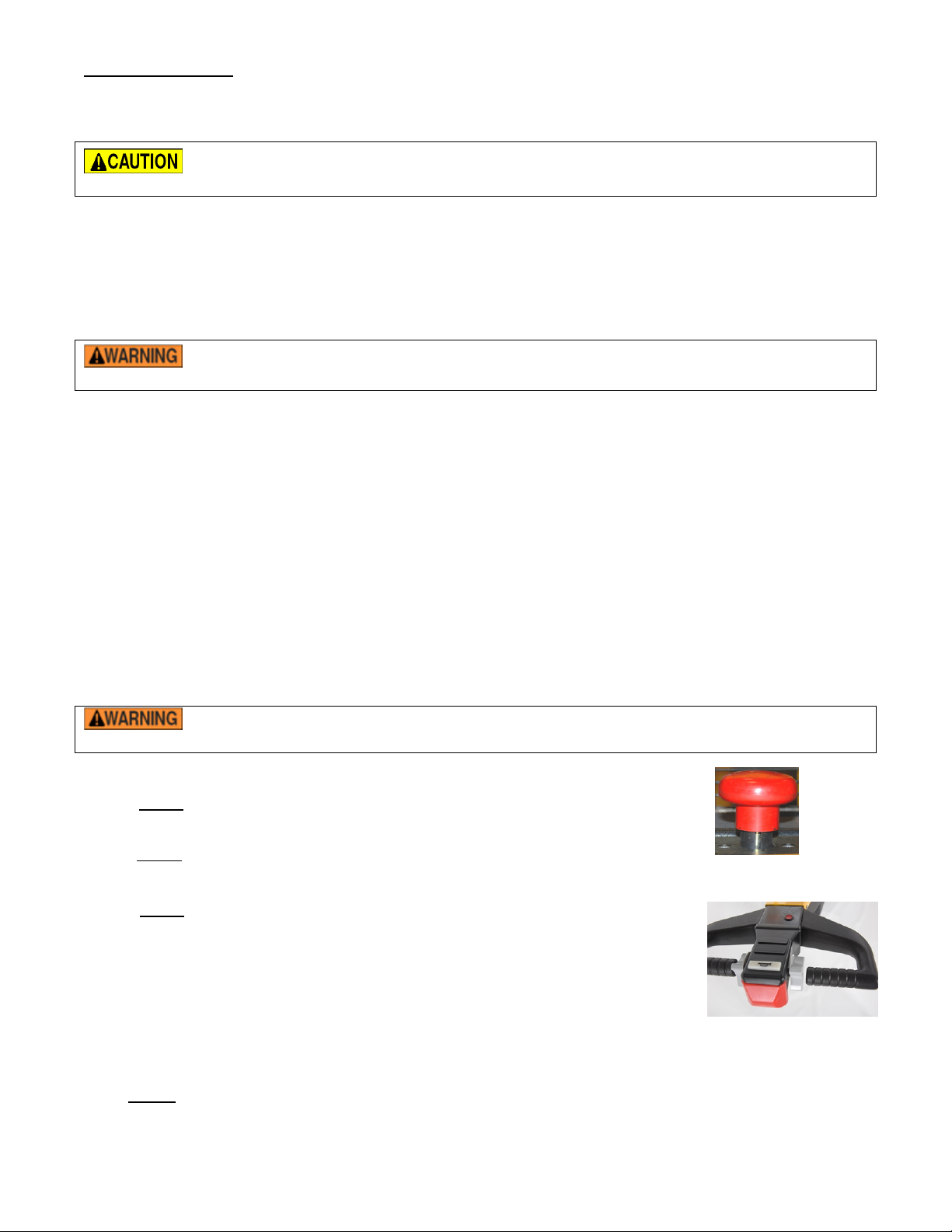
Unit will not move at all. Stuck Switch The belly switch is stuck on. Tap
the orange belly switch assembly
to see if the switch can be freed.
If this doesn’t work, disassemble
the tiller head by removing 3
screws from bottom. Slightly
loosen up the two screws that
hold the switch in place, this may
free the switch. If it is still stuck,
contact the factory for a
replacement switch.

E-TUG-HD, Manual
Copyright 2021 Vestil Manufacturing Corp. Page 11 of 15
Problem: Possible cause(s): Action:
Unit will not reverse; belly switch
does not function; forward ok
Broken wire, or loose connection,
bad throttle assembly, bad motor
controller.
Locate Pin 12 on Molex
connector at the motor controller.
Try to drive the unit in reverse,
there should be 24 volts at this
pin. If there is voltage and the
unit does not move, the motor
controller may be bad, consult
factory. If there is no voltage,
trace the wiring back towards the
tiller head and check voltage on
each side of connectors.
Continue this until bad
connection is found. If the
connections are all good, and
there is no voltage coming out of
throttle assembly, then the
throttle assembly may be bad.
Verify there is 24 volts going into
the assembly, and that there is a
good ground. If there is still no
output voltage for pin 12, replace
throttle assembly.

E-TUG-HD, Manual
Copyright 2021 Vestil Manufacturing Corp. Page 12 of 15
Maintenance and Inspections:
According to ANSI B56.1, the tugger is a “motorized hand truck” (MHT). For this type of truck, only trained,
authorized persons should perform inspections or maintenance.
Inspections: ALWAYS review the following warning messages and procedures BEFORE inspecting the MHT.
DO NOT use the tugger if an inspection reveals structural damage. Structural damage
includes, but is not limited to, cracked welds, warping or other deformation of the brackets, front rollers and
wheel(s), handle, or the housing that protects the electrical components.
If an inspection exposes any problem, restore the MHT to normal operating condition BEFORE returning it to
regular service. The MHT must not be used until all repairs have been completed.
According to B56.1-2005:
A “User” is “a person or organization responsible for employing powered industrial trucks.” Therefore, the person
or business that owns the MHT is a user.
“Authorized” means any person designated by the user to operate or maintain the equipment. In other words, the
owner, most likely your employer, is responsible for training and selecting people to inspect and maintain the MHT.
NOTE: A user may choose to contract with a person or an organization for maintenance services. Vestil is not
responsible for the actions of independently contracted maintenance service providers.
Only use replacement parts either supplied or approved by the manufacturer.
The person(s) authorized by the end-user to inspect the MHT must do so before it is used for the first time, and
before each subsequent use. If the MHT is rarely used, inspect the unit at least once per month, or before each use,
whichever is more frequent. Before the inspection, a) disconnect the battery, and b) either chock the wheels or lift the
MHT until the drive wheels no longer contact the ground.
Inspect the pallet truck prior to each use. Specifically look for:
1. Frayed wires;
2.
3.
Pinched or damaged wires;
4.
Structural damage: cracked welds, warping or other deformation of the brackets, front rollers or drive
wheel(s), handle, or the housing that protects the electrical components;
5.
Proper function of all limit switches;
6.
Proper horn operation;
7.
Normal battery condition: clean, not leaking electrolyte solution, secure connections with both terminals.
Also make sure that the battery is immobilized so that it cannot move during operation.
Proper rotation of all wheels.
Inspect the MHT each month:
1.
2. Damage to or excessive wear of:
a. Pivot points;
b.
c.
Electric wires;
d.
Retaining rings for the rollers, drive wheels, and all pivot points;
Bearings
3.
Wobbliness or looseness of rollers and/or drive wheels;
4.
Proper function of the hand actuated mechanisms;
5.
Proper battery water level;
6.
Unusual noise or abnormal movement during operation;
Legibility and undamaged condition of all product labels.
Maintenance: the end-user must implement a scheduled maintenance program to ensure the proper function and
safety of the lifter. Pages 12-13 of ANSI/ITSDF standard B56.1-2005 describe some recommended maintenance
procedures, and the following steps should be utilized in conjunction with those recommendations.
The user is responsible for training persons to work on the MHT. “Work on” refers to operating,
loading, cleaning, servicing, maintaining, or repairing the product. ONLY trained, authorized maintenance personnel
or independent contractors chosen by the user should perform inspection, maintenance, or repair work.

E-TUG-HD, Manual
Copyright 2021 Vestil Manufacturing Corp. Page 13 of 15
Step 1: Tag the MHT, “Out of Service.”
Step 2: Complete an every use and a monthly inspection. If deformity, corrosion, rusting, or excessive wear of
structural members is present, DO NOT use the MHT. Contact Vestil for instructions.
Step 3: Remove any dirt or other matter from the forks and other surfaces.
Step 4: Perform all other necessary adjustments and/or repairs, but DO NOT modify the truck.
The reader should understand the significant difference between necessary adjustments and
repairs, and modifications.
An adjustment is a simple correction that restores the MHT to normal operating condition, such as tightening loose
fasteners, or removing dirt or other debris from the surface; a repair refers to replacing worn parts with new or
replacement parts.
DO NOT use the tugger if adjustments and/or repairs are incomplete! Return it to service ONLY after finishing all
necessary repairs and adjustments.
A modification is a change that alters the MHT from normal operating condition, like bending the structural members
or removing a part or several parts. NEVER modify the unit without the express, written approval of Vestil.
Modifications may render the product unsafe to use.
Step 5: Make a dated record of the repairs, adjustments and/or replacements made.

LIMITED WARRANTY
Vestil Manufacturing Corporation (Vestil) warrants each model of E-TUG-HD to be free of defects in material
and workmanship during the warranty period. Our warranty obligation is to provide a replacement for a
defective original part (a part used to make the product as shipped to the warrantee) after we receive a
proper request for warranty service. “Proper request” means that we must receive: 1) a photocopy of your
Customer Invoice that displays the shipping date; AND 2) a written request for warranty service that
includes your name and phone number. Send requests by any of the following methods.
Fax Email
2999 North Wayne Street, PO Box 507 Phone
Angola, IN 46703 (260) 665-7586
In the written request, list the parts you believe are defective and include the address where replacements
should be delivered. After Vestil receives your request, an authorized representative will contact you to
determine whether your claim is covered by the warranty (also see “If a defective part is covered…” below).
Before providing warranty service, Vestil may require you to send the entire product or the defective part or
parts to its facility in Angola, Indiana.
Who may request service?
Only the warrantee may request service. You are a warrantee if you purchased the product from Vestil or from
an authorized distributor AND Vestil has been fully paid.
What is covered under the warranty?
The warranty covers the following original drive and lift components: drive motors and lift motors, hydraulic
pumps, electronic controllers, switches and cylinders. It also covers original parts that wear under normal
usage conditions (“wearing parts”): bearings, hoses, wheels, seals, brushes, batteries, and the battery charger.
The warranty period for drive and lift components is 1 year. For wearing parts, the warranty period is 90 days.
Both warranty periods begin on the date when Vestil ships the product to the warrantee. If you purchased the
product from an authorized distributor, the periods begin when the distributor ships the product, which extends
the warranty by up to an additional 30 days.
If a defective part is covered by the warranty, what will Vestil do to correct the problem?
Vestil will provide an appropriate replacement for any covered part. An authorized representative of Vestil will
contact you to discuss your claim.
What is not covered by the warranty?
1. Labor costs or Freight;
2. Any of the following automatically void the warranty:
•Product misuse;
•Negligent operation or repair;
•Corrosion or use in corrosive conditions;
•Inadequate or improper maintenance;
•Failure to exercise good judgment;
•Damage sustained during shipping;
•Accidents involving the product;
•Unauthorized modifications: Do NOT modify the product IN ANY WAY without first receiving
written authorization from Vestil. Modifications may render the pallet truck or stacker unsafe
to use or might cause excessive and/or abnormal wear.
Do any other warranties apply to the product?
Vestil Manufacturing Corp. makes no other express warranties. Any warranty implied-by-law is limited in
duration to the warranty period.
E-TUG-HD, Manual
Mail
Page 14 of 15

E-TUG-HD, Manual
Copyright 221 Vestil Manufacturing Corp. Page 15 of 115
MARKINGS:
Only use the lifter if ALL labels are readable and undamaged. Contact Vestil for replacement labels if necessary,
and DO NOT use the pallet truck until all replacement labels are affixed to the device.
Proper label placement is shown below:
Label #295
Label #220
Label #208
Label #527
Table of contents
Other Vestil Jack manuals
Popular Jack manuals by other brands

Westward
Westward 1ZKX4 Operating instructions & parts manual

Surewerx
Surewerx Strongarm 806B Operator's manual

Pittsburgh
Pittsburgh 61523 Owner's manual & safety instructions

Berner
Berner DK20 user guide

Sealey
Sealey 3000CXd.V2 instructions

Clarke
Clarke Strong-Arm CFT5 Installation, operation & maintenance instructions

Clarke
Clarke STRONG-ARM CTJ2500QLGB Operating & maintenance instructions

MARTINS Industries
MARTINS Industries MFJ-PL2T manual

Evercraft
Evercraft 776-2007 manual

ATD Tools
ATD Tools ATD-7328 Operating instructions & parts manual

Tronair
Tronair 02-0511C0132 Operation & service manual

Titan
Titan FJ3T Installation, operation & maintenance manual