Vetta VL110A User manual

I
INTRODUCTION.............................................................. 1
WARNINGS & CAUTIONS .............................................. 1
FUNCTIONS / FEATURES .............................................. 2
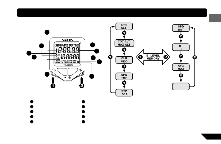
VL110A ILLUSTRATIONS ............................................... 3
HEAD UNIT................................................................ 3
COMPONENTS ......................................................... 4
BUTTON FUNCTIONS..................................................... 5
SCREEN DISPLAY SEQUENCE: BI-LEVEL MEMORY ...... 7
HOW TO RECOGNIZE YOUR TORPEDO (T2X MODEL ONLY)
...........
8
SETUP & PROGRAMMING............................................. 10
INITIAL SETUP .......................................................... 10
System Check ..................................................... 10
NOM Setup ................................................................ 10
Setup: Dual Bike.................................................. 11
Setup: Altitude Units............................................ 11
Setup: Altimeter ON/OFF .................................... 12
Setup: Altimeter Memory 1 .................................. 12
Setup: Altimeter Memory 2 .................................. 13
Setup: Wheel Circumference .............................. 13
Setup: Service Timer........................................... 15
Setup: Speed Units ............................................. 16
Setup: Temperature Units.................................... 16
Setup: Clock........................................................ 16
Setup: Odometer................................................. 17
Setup: SmartLite ON/OFF................................... 17
Setup: SmartLite Interval – From ........................ 18
Setup: SmartLite Interval – To............................. 18
Exit ...................................................................... 18
System Check ..................................................... 19
PRIMARY SCREEN MODES ........................................... 20
UPPER SCREEN MODES......................................... 20
SPD/DST............................................................. 20
RT/TT .................................................................. 21
AVG/MAX ............................................................ 22
SPD*/CAD*.......................................................... 22
LOWER SCREEN MODES........................................ 23
SPD/ALT.............................................................. 23
CONTENTS
ENGLISH

OPERATION
II
PRE-RIDE ALTIMETER CALIBRATION......... 24
TOT ALT/MAX ALT .............................................. 26
CLK/ODO ............................................................ 27
SPD/TMP ............................................................ 28
STP/ID................................................................. 29
STP/IA................................................................. 30
SECONDARY SCREEN MODES.................................... 31
AVG CAD*/MAX CAD* ........................................ 31
MAX TMP/MIN TMP............................................ 31
OTHER FEATURES......................................................... 32
SLEEP MODE............................................................ 32
AUTO FIRE UP .......................................................... 32
SMART LITE .............................................................. 33
DUAL BIKE MEMORY....................................... 33
SERVICE TIMER ............................................. 33
SPEED COMPARATOR.................................... 34
LOW BATTERY WARNING............................... 34
FREEZE FRAME MEMORY ............................. 36
RESET ................................................................... 37
RIDE DATA RESET........................................... 37
STOPWATCH & INTERMEDIATE DISTANCE RESET
.......
37
STOPWATCH & INTERMEDIATE ALTITUDE RESET
........
37
ALL CLEAR TOTAL RESET .............................. 37
TROUBLE SHOOTING........................................... 38
TECHNICAL SPECIFICATIONS ............................. 40
WARRANTY POLICY ............................................. 41
CUSTOMER SERVICE CENTERS ......................... 42
CONTENTS
ENGLISH

1
ENG
INTRODUCTION
Thank you for purchasing a Vetta VL110A cycle computer. Please take time to familiarize yourself with all the functions of the
VL110A model so you can take full advantage of its programs. And don’t forget to store this manual in a safe place for future
reference!
WARNINGS & CAUTIONS
▪ Vetta recommends that this product be installed only by a qualified bicycle retailer. Failure to read these instructions and/or
improper installation of this device may void the warranty. If in doubt about any aspect of the installation or operation of this
product, consult your local bicycle retailer for clarification.
▪ The VL110A cycle computer is a general indicator of altitude; it is not suitable or intended for any use other than cycling.
Elevation value displayed by the VL110A may be subjected to slight fluctuations due to changes in ambient temperature
and weather.
▪ The Head Unit is water resistant and sealed to withstand wet weather conditions. Do not deliberately place it in water.
▪ Avoid leaving the Head Unit exposed to extremely hot or cold weather conditions.

2
ENG
Smart Signal ●
Current / Average / Maximum Speed ●●●
Speed Comparator ●●●
Cumulative Odometer ●●●
Trip Distance ●●●
Intermediate Distance ●●●
Current / Maximum Altitude ●●●
Total Altitude Gain ●●●
Intermediate Altitude Gain ●●●
Barometric Calibration ●●●
12/24 Hour Clock ●●●
Stopwatch ●●●
Ride Time ●●●
Total Time ●●●
Service Timer ●●●
Ambient Temperature ●●●
Maximum / Minimum Temperature ●●●
Dual Bike Memory ●●●
Freeze Frame Memory ●●●
Energy Saving Sleep Mode ●●●
Low Battery Warning (Head Unit) ●●●
Low Battery Warning LED Indicator (Torpedo)
●
Auto Fire Up - Auto Start up & Awake ●●●
NiteLite with SmartLite Function ●●●
Current / Average / Maximum Cadence
●
FUNCTIONS / FEATURES
HD T2XWL HD T2XWL

3
ENG
VL110A ILLUSTRATIONS
HEAD UNIT
ADCBE
A
B
C
D
E
F
G
H
H
FG

4
ENG
COMPONENTS
,
)
)
/
.
"
!
4
4
%
2
9
6
CR 2450
For All Models
A
Bladed Spoke Magnet (SPD Magnet)
B
Spacer
C
Bracket Rubber Pad
D
Bracket Rubber Pad (Riser Handlebar)
E
Wireless Transmitter Shim /Torpedo Shim
F
Zip-Ties
G
Head Unit Battery (CR2450, 3-Volt)
For VL110A HD
H
Wired Speed Sensor with
Mounting Bracket
I
Wire Securing Tape
For VL110A WL
J
WL Wireless Speed Transmitter
K
WL Wireless Speed Active Mount
L
Wireless Transmitter Battery
(A23, 12-Volt)
M
Wireless Transmitter Battery Cap
For VL110A T2X
N
Integrated T2X Torpedo
O
Integrated T2X Active Mount
P
Composite Cadence Magnet
(CAD Magnet)
Q
Torpedo Battery (CR123A, 3-Volt)
R
Torpedo Battery Cap

5
ENG
Button
Button
Button
1
3
Button 4
2
BUTTON FUNCTIONS
Button
1
Sets digits or units
Advances to the next item, screen or setting mode
Button
2
Advances digits or toggles through units
Hold for fast advance
Resets RT to zero for Service Timer
Button
3
Has no function in Initial Setup
Button
4
Turn on the NiteLite for 3 seconds
SETUP MODE
Button
1
Scrolls through Lower Screen Modes
Scrolls through Freeze Frame display screens
Hold 2 seconds in SPD/TMP Mode to display Maximum and
Minimum Temperature
Hold 2 seconds in SPD/CAD* Mode to display Average and
Maximum Cadence ( *T2X model only)
Hold 2 seconds in STP/ID Mode to switch to STP/IA Mode (or
hold 2 seconds in STP/IA Mode to switch to STP/ID Mode)
Button
2
Scrolls through Upper Screen Modes
Press and hold 2 seconds in any Upper/Lower Screen Mode
to activate Freeze Frame memory
OPERATING MODE

6
ENG
Button
Button
Button
1
3
Button 4
2
OPERATING MODE
Button
3
Starts/stops RT/TT timers and Stopwatch
Reset RT/TT timers and other ride data to zero
Exits NOM Setup and advances to NOM System Check and
SPD/DST Mode
Button
4
Turn on the NiteLite for 3 seconds
Button
1
&
2
(
simultaneously for 2 seconds with RT/TT Timers are off
) :
Hold both in the SPD/DST Mode to enter NOM Setup
Hold both in the SPD/ALT Mode to enter Pre-Ride Altimeter
Calibration Setup
For T2X model only
Button
2
&
4
(
simultaneously for 2 seconds with RT/TT Timers are off
) :
Hold both in the SPD/DST Mode to enter ID Learning Setup Mode

7
ENG
A
Upper Screen Mode
B
Upper Display
C
Lower Display
D
Lower Screen Mode
E
Bicycle Icon
SCREEN DISPLAY SEQUENCE: BI-LEVEL MEMORY
J
H
I
G
FE
D
B
C
A
SPD*
CAD
F
Altimeter and Barometric Pressure Unit Symbols
G
Temperature Icon
H
Service Timer/ Low Battery Icon
I
Stopwatch Icon
J
Speed Comparator Symbol
Remark: ( * ) Available until Upgrade to T2X model

8
ENG
HOW TO RECOGNIZE YOUR INTEGRATED T2X TORPEDO (T2X MODEL ONLY)
1. For VL110A T2X or Upgrade to T2X models, your computer can ONLY recognize the Integrated T2X Torpedo after it goes
through the ID Learning procedure.
2. If your Integrated T2X Torpedo is purchased as a complete set with the VL110A series computer, your computer has been
programmed to recognize the Torpedo in the factory.
3. If a new Integrated T2X Torpedo or Integrated T2X Active Mount is purchased for replacement, please follow the ID
Learning Procedure.
4. If a complete set of Integrated T2X Mounting Kit is purchased for your 2nd bike, please make sure you had chosen Bike II in
the NOM Setup Mode (see page 11, Section of Dual Bike Setup in NOM Setup), and follow the ID Learning Procedure.

9
ENG
ID LEARNING PROCEDURE
Step 1: Install the computer on the Integrated T2X Active Mount.
Step 2: After the screen display “id NEEd”, press & hold the Torpedo’s button for 3 seconds.The Light
Ring Indicator of the Torpedo will turn on for 2 seconds in red.
Step 3: During the process, the computer will display “id LEArn” for 3 seconds.
Step 4: When done successfully, the computer will display “id donE” and gives 2 short beeps. The
computer will go back to the screen last displayed.
FAILURE
If the computer always displays “id NEEd”, please check if there are any objects emitting
electromagnetic waves (television, radio control toys, etc.). Keep the unit away from any object that
may be causing interference. Then press & hold the Torpedo’ button for 3 seconds again, and follow
the Step 3 & 4 to finish the ID Learning Procedure.
If this cannot solve the problem, re-install the battery and start from the Step 1 (as above) again.
Important To re-activate the ID Learning Procedure, press & hold
2
&
4
simultaneously for 2
seconds in the SPD/DST Mode with RT/TT timers are off.

10
ENG
SETUP & PROGRAMMING
INITIAL SETUP
The computer will automatically go into the Initial Setup Mode after
1. New battery repalcement, or
2. All Clear Total Reset
In the Initial Setup, riders can program the Basic Settings for the computer, the content of settings are same as NOM Setup for
Basic Setting (see page 11, Section of NOM Setup for Basic Setting)
Important To change any values or correct any unit errors made during Initial Setup, you must re-enter the NOM Setup by
pressing
1
and
2
simultaneously for 2 seconds in the SPD/DST Mode with the RT/TT timers deactivated.
SYSTEM CHECK
●After the last setting, the computer will automatically advance to System Check.
●System Check displays all value and unit settings chosen during Setup in sequence.
●Each screen in System Check appears for 5 seconds and blink.
NOM SETUP
After completed the Initial Setup, riders can change any values or correct any errors by re-entering the NOM Setup.

11
ENG
HOW TO ENTER THE NOM SETUP MODE?
1. Make sure RT/TT timers are off (press
3
in the RT/TT Mode and will disappear)
2. Advance to the SPD/DST Mode by using
2
.
3. Press & hold
1
&
2
to enter the NOM Setup Mode.
Important Press
3
at any time to exit NOM Setup Mode and advance to System Check.
SETUP: DUAL BIKE
1. Press
2
to toggle between Bike 1 or Bike 2
2. Press
1
to select and advance to the next Setup Mode.
SETUP: ALTITUDE UNITS
1. Press
2
to toggle between feet or meter
2. Press
1
to select and advance to the next Setup Mode.

12
ENG
SETUP: ALTIMETER ON/OFF
1. Press
2
to toggle between ON/OFF
2. Press
1
to select and advance to the next Setup Mode.
3. If set to OFF, the computer will jump to the Wheel Circumference Setup
Mode.
SETUP: ALTIMETER MEMORY 1
1. When the far right digit begins to flash, press
2
to scroll to the desired number
2. Press
1
to select this no. and advance to next flashing digit
3. Repeat for each digit until the final digit
4. Press
1
and advance to the next Setup Mode.

13
ENG
SETUP: ALTIMETER MEMORY 2
1. When the far right digit begins to flash, press
2
to scroll to the desired number
2. Press
1
to select this no. and advance to next flashing digit
3. Repeat for each digit until the final digit
4. Press
1
and advance to the next Setup Mode.
SETUP: WHEEL CIRCUMFERENCE
1. When the far right digit begins to flash, press
2
to scroll to the desired number. (see page 14, Section of WHEEL SIZE
CALCULATION)
2. Press
1
to select this no. and advance to next flashing digit.
3. Repeat for each digit until the final digit.
4. Press
1
and advance to the next Setup Mode.

14
ENG
WHEEL SIZE CALCULATION
Find your tire size and record the corresponding circumference measurement from the following chart lists.
If your wheel size in not on the chart, or if you want a more precise calibration, wheel circumference may be calculated as
follows:
Step1: Measure the distance from the centre of the front wheel axle the ground in millimetres. (1 inch =25.4 mm)
Step2: Multiply this distance by 6.2832(2π) and enter the result as the wheel size setting into the computer.
OR… Mark the tire and a spot on the floor. Roll the wheel forward one complete revolution until the tire mark touches the
floor again and mark that spot. Measure the distance between the marks on the floor millimeters and enter the result into the
computer.

15
ENG
SETUP: SERVICE TIMER
Step 1: Service Timer Interval (in hour)
Service Timer will be disabled when Service Timer Interval is set to “0000”
1. When the lower far right digit begins to flash, press
2
to scroll to the desired number.
2. Press
1
to select this no. and advance to next flashing digit.
3. Repeat for each digit until the final digit.
4. Press
1
and advance to the Accumulated RT Reset Mode. (see Step 2)
Important In the Initial Setup, the Accumulated RT Reset Mode doesn’t exist, press
1
will advance to the next Speed
Units Setup Mode.
Step 2: Accumulated Ride Time (in hour)
To stop the Service Timer icon from flashing, reset the Accumulated RT
to Zero.
When the upper digits begin to flash, press & hold
2
to reset Accumulated
RT to Zero.
OR press
1
repeatedly to reserve the digits, and advance to the next
Setup mode.

16
ENG
SETUP: SPEED UNITS
1. Press
2
to toggle between KM/hr or Mile/hr
2. Press
1
to select and advance to the next Setup Mode.
SETUP: TEMPERATURE UNITS
1. Press
2
to toggle between °C or °F.
2. Press
1
to select and advance to the next Setup Mode.
SETUP: CLOCK
1. Press
2
to toggle between 12hr or 24hr format, PM icon will appear only in the 12hr format.
2. Press
1
to select and advance to “hh:mm” setup.
3. When the far right digits begin to flash, press
2
to scroll to the desired number.
4. Press
1
to select this no. and advance to next flashing digit
5. Repeat for each digit until the final digit
6. Press
1
and advance to the next Setup Mode.

17
ENG
SETUP: ODOMETER
1. When the far right digit begins to flash, press
2
to
scroll to the desired number
2. Press
1
to select this no. and advance to next
flashing digit
3. Repeat for each digit until the final digit
4. Press
1
and advance to the next Setup Mode.
SETUP: SMARTLITE ON/OFF
1. Press
2
to toggle between ON or OFF
2. Press
1
to select. If set to ON, the computer will advance to the next
Setup Mode.
3. If OFF, it will exit the Setup mode and advance to System Check.

18
ENG
SETUP: SMARTLITE INTERVAL – FROM
1. Press
2
to scroll from 1:00 PM to 11:00 PM
2. Press
1
to select and advance to the next Setup Mode.
SETUP: SMARTLITE INTERVAL – TO
1. Press
2
to scroll from 1:00 AM to 11:00 AM
2. Press
1
to select and exit the Setup Mode and advance to System Check
EXIT
Press
3
at any time during the NOM Setup, and exit to System Check
Important If no buttons are pressed for approximately 5 minutes during Setup, the computer will automatically enter Sleep
Mode and then return to the screen last displayed when reactivated.
Table of contents
Other Vetta Bicycle Accessories manuals

Vetta
Vetta V50 User manual

Vetta
Vetta c-500 User manual

Vetta
Vetta RT55 User manual

Vetta
Vetta C-06 CYCLE COMPUTER User manual

Vetta
Vetta V30 User manual

Vetta
Vetta Solar Flare500-111 User manual

Vetta
Vetta V80 User manual

Vetta
Vetta CYCLE COMPUTER User manual

Vetta
Vetta RT255L Instruction manual

Vetta
Vetta VL110 User manual