Vetus RCTOPB User manual

030606.07
NEDERLANDS 2
ENGLISH 4
DEUTSCH 6
FRANÇAIS 8
ESPAÑOL 10
ITALIANO 12
Installatie- en gebruikershandleiding
Mechanische motorafstandsbediening
Installation and user manual
Mechanical remote engine control
Installations- und Benutzerhandbuch
Mechanische Motor-Fernbedienung
Manuel d’Installation et d’utilisation
Télécommande mécanique pour moteur
Manual de instalación y usuario
Mando a distancia mecánico para motores
Manuale d’installazione e d’uso
Telecomandi meccanici per motori
Mechanical remote engine control
Copyright © 2022 Vetus b.v. Schiedam Holland
Installation and user manual
RCTOPB RCTOPBG RCTOPS RCTOPSG
RCTOPTB RCTOPTBG RCTOPTS RCTOPTSG
SICO SICOG SISCO SISCOG

2 030606.07 Mechanical remote engine control
1 Inleiding
Met de Vetus mechanische motorafstandsbedieningen worden zo-
wel de koppeling als de brandstofpomp door middel van één handel
bediend.
2 Installatie
2.1 Trek-drukkabels aan het mechanisme
Het mechanisme is direct geschikt voor het bedienen van de:
• brandstofpomp (gas geven) -‘duwend’
-‘trekkend’
• keerkoppeling (schakelen)
-‘duwend-vooruit’en‘trekkend-achteruit’
-‘duwend-achteruit’en‘trekkend-vooruit’
Raadpleeg bij twijfel de motorleverancier wanneer niet duidelijk is
hoe de bediening van de motor is wat betreft gas geven en schake-
len (‘duwend’of‘trekkend’).
Let op!
Verbind altijd eerst de kabels met het mechanisme. Het verbin-
den van de kabels met de keerkoppeling en de brandstofpomp
dient pas te gebeuren wanneer de complete afstandsbediening
geïnstalleerd is.
Verwijder altijd eerst de handel en het deel van het huis (bij RC-
TOP..) of de handel en de plaat bij (SI(S)CO(G)) van het mechanis-
me, voordat de kabels aan het mechanisme verbonden gaan worden
(zie tekeningen rechter pagina).
Naast het door Vetus en Morse geleverde kabeltype 33C, is het me-
chanisme ook geschikt voor kabeltype OS van OMC en kabeltype KM
van Mercury.
De bevestigingsgaten in het mechanisme zijn genummerd. Deze
nummers corresponderen met het type kabel:
Functie Type kabel ‘Duwend’ ‘Trekkend’
Gasgeven Alle
Schakelen
(vooruit)
33C
OS
KM
Zorg ervoor dat beide functies van het mechanisme in de neu-
traalstand staan alvorens de kabels aan te sluiten.
Gaskabel aansluiten:
‘Duwend’gas geven : zie tekening 1 op pagina 14
‘Trekkend’ gas geven : zie tekening 2 op pagina 14
Koppelingskabel aansluiten:
‘Duwend-vooruit’ en ‘trekkend-achteruit’ schakelen: tekening 3 op
pagina 14
‘Duwend-achteruit’ en ‘trekkend-vooruit’ schakelen: tekening 4 op
pagina 14
Let bij installatie van de kabels verder op de volgende punten:
• Zorg voor de juiste (totale) kabellengte.
• Leg zo min mogelijk bochten in de kabel en neem de buigradius
zo groot mogelijk (minimaal 500 mm).
• De kabels moeten op regelmatige afstanden worden gebeugeld
(elke 60 cm).
• Installeer de kabel niet te dicht bij warmtebronnen, zoals de ver-
schillende delen van het uitlaatsysteem.
• Voorkom schuren van de kabel.
• Controleer na installatie aan het mechanisme of de kabels zonder
noemenswaardige weerstand kunnen worden bewogen.
2.2 Trek-drukkabels aan de motor
Verbind de kabels met de keerkoppeling en de brandstofpomp zoals
door de motorleverancier is voorgeschreven.
Controleer of de hefboom van de brandstofpomp op de motor zijn
eindpositie haalt wanneer de handel in de uiterste stand wordt ge-
zet.
Controleer tevens de juiste werking van de keerkoppeling.
2.3 Neutraalschakelaar
Het mechanisme is reeds voorzien van een neutraalschakelaar. De
neutraalschakelaar verhindert dat de motor kan worden gestart
wanneer de keerkoppeling nog ingeschakeld is.
Indien gebruik wordt gemaakt van de neutraalschakelaar, sluit de
neutraalschakelaar dan aan zoals in de elektrische schema ’s op pagi-
na 15 is aangegeven.
2.4 Meerdere afstandsbedieningen
Wanneer een motor is uitgerust met twee afstandsbedieningen, die-
nen dierentiaal apparaten aangeschaft te worden.
Met dierentiaal apparaten kunnen de beide afstandsbedieningen
met elkaar worden verbonden, zodat de motor vanaf twee plaatsen,
onafhankelijk van elkaar, bediend kan worden.
Per motor zijn twee dierentiaal apparaten nodig, namelijk één voor
de keerkoppeling en één voor de brandstofpomp. Zie tekening op
pagina 15.
2.5 Huis en handel
Houd bij het kiezen van de plaats waar het huis en de handel gemon-
teerd worden, rekening met de maximale uitslag die de handel kan
maken. Houd tevens rekening met de totale lengte van het mecha-
nisme. Zie tekening‘Hoofdafmetingen’.
NEDERLANDS

030606.07 3
Mechanical remote engine control
Topmontage:
• Teken met behulp van de meegeleverde boormal de te boren be-
vestigingsgaten en de uit te zagen opening af.
• De twee beugels aan het gedeelte dienen als bevestigings-
beugels. Controleer of de bevestigingsgaten overeenkomen met
de afgetekende gaten.
• Boor de gaten en zaag de opening uit.
• Breng de meegeleverde zelfklevende pakking op de juiste wij-
ze aan.
• Monteer de afstandsbediening met bouten M5 met de juiste
lengte.
• Monteer nu het gedeelte van het huis.
Zijmontage:
De afstandsbediening voor zijmontage heeft een vrije ruimte van
minimaal 180 mm achter het schot nodig om het geheel te kunnen
monteren.
• Teken met behulp van de meegeleverde boormal de te boren be-
vestigingsgaten en de uit te zagen opening af.
• Boor de gaten en zaag de opening uit.
• Breng de meegeleverde inseal op de juiste wijze aan de achter-
zijde van de plaat aan. Zie detail.
• Bevestig het mechanisme aan de plaat .
• Bevestig nu het geheel met bouten tegen het schot.
• Vet de as van het mechanisme in en monteer de handel in de ge-
wenste positie (meestal verticaal).
• Voorzie de bout M10 van een borgmiddel (Loctite®243).
• Controleer het verloop van de kabels.
5 Onderhoud
• Reinig, indien noodzakelijk, de handel en het huis met
zoet water.
• Controleer regelmatig het mechanisme op los zitten-
de onderdelen en op slijtage van de bewegende de-
len.
Smeer regelmatig de bewegende delen met een
vochtverdrijvende smeerolie.
• Controleer regelmatig de kabels en de kabelverbin-
dingen op slijtage en corrosie.
3 Afstelling
Met schroef 1 kan de frictie voor het gasmechanis-
me worden ingesteld, afhankelijk van de tegendruk
van de brandstofpomp.
4 Bediening
Met drukknop 2 kan de bediening van de keerkop-
peling worden uitgeschakeld, zodat alleen gas ge-
geven kan worden, bijvoorbeeld voor het starten en
opwarmen van de motor.
Wanneer de handel weer in de neutraalstand wordt
gezet, zal de drukknop terugspringen en is de af-
standsbediening gereed voor normaal gebruik.
• Vet de as van het mechanisme in en monteer de handel in de
gewenste positie (meestal verticaal).
• Voorzie de bout M10 van een borgmiddel (Loctite®243).
• Controleer het verloop van de kabels.
NEDERLANDS

4 030606.07 Mechanical remote engine control
1 Introduction
With the Vetus mechanical remote engine control both the gearbox
and the throttle can be controlled my means of one lever.
2 Installation
2.1 Pull-push cables on the mechanism
The mechanism is directly suitable for control of the:
• throttle (to accelerate) - ‘pushing’
- ‘pulling’
• gearbox (to change gear)
- ‘push to go forward’ and ‘pull to go backward’
- ‘push to go backward’ and ‘pull to go forward’
When in doubt, consult the engine supplier if is it not clear how the
control of the engine is arranged with regard to accelerating and
changing gear (‘pushing’or ‘pulling’).
Warning!
Always connect the cables to the mechanism first. You should
only connect the cables to the gearbox and the throttle after
the complete remote control mechanism has been installed.
Always remove the lever and part of the housing first (with
RCTOP..) or the lever and the plate (with SI(S)CO(G)) of the mecha-
nism, before the cables are mounted on the mechanism (see draw-
ing on right-hand page).
Besides the cable type 33C supplied by Vetus and Morse, the mecha-
nism is also suitable for use with cable type OS from OMC and cable
type KM from Mercury.
The mounting holes in the mechanism are numbered. These num-
bers correspond with the type of cable:
Function Type of cable ‘Pushing’ ‘Pulling’
Acceleration All types
Gear-change
(forward)
33C
OS
KM
Ensure that both functions of the mechanism are in the neutral posi-
tion before connecting the cables.
Connecting the gas cable:
‘Pushing’ accelerating : see drawing 1 on page 14
‘Pulling’ accelerating : see drawing 2 on page 14
Connecting the gear cable:
‘Pushing-forward’ and ‘pulling-backwards’ gear change:
see drawing 3 on page 14
‘Pushing-backwards’ and ‘pulling-forward’ gear change:
see drawing 4 on page 14
When installing the cables, also take note of the following points:
• Make sure you have enough (total) length of cable.
• Make as few bends in the cable as possible, and use the largest
possible bending radius (at least 500 mm (20”)).
• The cables must be clamped at regular distances (every 60 cm
(24”)).
• Do not install the cables close to heat sources, such as the various
parts of the exhaust system.
• Prevent abrasion of the cable.
• After installation on the mechanism, check whether the cables
can move without appreciable resistance.
2.2 Pull-push cables on the engine
Connect the cables with the gearbox and the throttle, as prescribed
by the engine supplier.
Check whether the throttle lever on the engine reaches its end posi-
tion when the lever is at its farthest position.
Also check to make sure the gearbox works correctly.
2.3 Neutral switch
The mechanism is also equipped with a neutral switch. The neutral
switch prevents the engine from being started while the gearbox is
still engaged.
If the neutral switch is to be used, connect it as shown in the electri-
cal circuit diagrams on page 15.
2.4 Multiple remote controls
Whenever a engine is fitted out with two remote controls, differen-
tial devices should be procured.
With differential devices, both remote controls can be connected
to one another, so that the engine can be independently controlled
from two places.
Two differential devices are needed per engine, namely one for the
gearbox and one for the throttle. See drawing on page 15.
2.5 Housing and Lever
When selecting the place where the housing and lever will be
mounted, account for the maximum swing that the lever can make.
Also account for the total height of the mechanism. See drawing
‘Principal dimensions’.
ENGLISH

030606.07 5
Mechanical remote engine control
ENGLISH
Top mounting:
• With the help of the supplied drill pattern,sketch the mounting
holes to be drilled and the opening to be sawed out.
• The two brackets on part should serve as mounting brackets.
Make sure that the mounting holes line up with the sketched
holes.
• Drill the holes and saw out the opening.
• Apply the supplied self-stick spacer in the correct manner.
• Assemble the remote control with M5 bolts of the correct length.
• Now assemble part of the housing.
• Grease the axle of the mechanism , and mount the lever in the
desired position (usually vertical).
Side mounting:
The remote control for side mounting requires a space of at least 180
mm (7”) behind the shot in order to assemble the entire mechanism.
• With the help of the supplied drill pattern, sketch the mounting
holes to be drilled and the opening to be sawed out.
• Drill the holes and saw out the opening.
• Apply the supplied inseal correctly on the back of plate . See
inset.
• Attach the mechanism to plate .
• Then attach the entire mechanism to the shot with bolts.
• Grease the axle of the mechanism, and mount the lever in the
desired position (usually vertical).
• Provide the bolt M10 with a screwlock (Loctite®243).
• Check the path of the cables.
5 Maintenance
• Clean, as necessary, the lever and the housing with
freshwater.
• Check the mechanism for loose components and for
wear of the moving parts on a regular basis.
Apply a water-resistant lubricant to the moving parts
routinely.
• Check the cables and the cable connections for wear
and corrosion on a regular basis.
3 Adjustments
Screw 1 can be adjusted to set the friction for the
gas mechanism, depending on the counter pres-
sure of the throttle.
4 Control
Button 2 can be used to turn off the control of the
gearbox, so that gas can only be given. (For exam-
ple, for starting and warming up the engine.)
When the lever is returned to the neutral position,
the button will pop back out, and the remote con-
trol is ready for normal use.
• Provide the bolt M10 with a screwlock (Loctite®243).
• Check the path of the cables.

6 030606.07 Mechanical remote engine control
1 Einleitung
Mit den mechanischen Vetus-Motor-Fernbedienungen wird sowohl
die Kupplung als die Treibstoffpumpe mit Hilfe eines Hebels bedient.
2 Installation
2.1 Zug-Druck-Kabel an den Mechanismus
Der Mechanismus eignet sich sofort zur Bedienung:
• der Treibstoffpumpe (Gas geben) - ‘durch Druck’
- ‘durch Zug’
• des Wendegetriebes (schalten)
- ‘durch Druck vorwärts’ und ‘durch Zug rückwärts’
- ‘durch Druck rückwärts’ und ‘durch Zug vorwärts’
Falls nicht klar ist, wie die Bedienung des Motors in Bezug auf
das Gas geben und Schalten (‘Druck’ oder ‘Zug’) funktioniert, den
Motorlieferanten zu Rate ziehen.
achtung!
Erst alle Kabel mit dem Mechanismus verbinden. Das Verbinden
der Kabel mit dem Wendegetriebe und der Treibstoffpumpe hat
erst zu erfolgen, nachdem die gesamte Fernbedienung instal-
liert worden ist.
Ehe die Kabel beim Mechanismus verbunden werden, erst den Hebel
und das Element des Gehäuses (bei RCTOP..) beziehungsweise
den Hebel und die Scheibe (bei SI(S)CO(G)) vom Mechanismus
entfernen (siehe Zeichnung auf der rechten Seite).
Außer für den von Vetus und Morse gelieferten 33C-Kabeltyp eig-
net sich der Mechanismus für den OS-Kabeltyp von OMV und den
KM-Kabeltyp von Mercury.
Die Befestigungslöcher im Mechanismus sind nummeriert. Diese
Nummern entsprechen dem Kabeltyp:
Funktion Kabeltyp ‘durch
Druck’ ‘durch Zug’
Gas geben alle
Schalten
(vorwärts)
33C
OS
KM
Darauf achten, dass sich beide Funktionen des Mechanismus im
Leerlaufstand befinden, bevor die Kabel angeschlossen werden.
Gaskabel anschließen:
‘Durch Druck’ Gas geben : siehe Zeichnung 1 auf Seite 14
‘Durch Zug’ Gas geben : siehe Zeichnung 2 auf Seite 14
Kupplungskabel anschließen:
‘Durch Druck vorwärts’und‘durch Zug rückwärts’schalten: Zeichnung
3 auf Seite 14
‘Durch Druck rückwärts’und‘durch Zug vorwärts’schalten: Zeichnung
4 auf Seite 14
Bei der Installation der Kabel ferner folgende Punkte beachten:
• Für eine entsprechende (Gesamt)kabellänge sorgen
• Möglichst wenig Kurven in das Kabel legen und den Biegeradius
möglichst groß halten (mindestens 500 mm).
• Die Kabel sind in regelmäßigen Abständen mit Kabelschellen zu
befestigen (alle 60 cm).
• Die Kabel nicht zu nahe bei Hitzequellen (wie den diversen Teilen
des Auspusystems) installieren.
• Scheuern des Kabels verhüten.
• Nach der Installation des Mechanismus prüfen, ob die Kabel ohne
nennenswerten Widerstand bewegt werden können.
2.2 Zug-Druck-Kabel am Motor
Die Kabel gemäß den Angaben des Motorlieferanten mit dem
Wendegetriebe und der Treibstoffpumpe verbinden.
Prüfen, ob der Hebelarm der Treibstoffpumpe am Motor seine
Endposition erreicht, wenn der Hebel in den äußersten Stand
geschaltet wird.
Prüfen, ob das Wendegetriebe ordnungsgemäß funktioniert.
2.3 Leerlaufschalter
Der Mechanismus ist bereits mit einem Leerlaufschalter ausge-
stattet. Der Leerlaufschalter verhindert, dass der Motor gestartet
werden kann, wenn das Wendegetriebe noch nicht eingeschaltet ist.
Falls der Leerlaufschalter benutzt werden soll, den Leerlaufschalter
gemäß dem auf Seite 15 angegebenen elektrischen Schaltplan
anschließen.
2.4 Mehrere Hebel-Fernbedienungen
Wenn ein Motor mit zwei Hebel-Fernbedienungen ausgestattet ist,
sind Differenzialschalter hinzuzufügen.
Mit Differenzialschaltern lassen sich die beiden Hebel-
Fernbedienungen miteinander verbinden, sodass sich der Motor
von zwei Stellen aus, unabhängig voneinander, bedienen lässt.
Pro Motor sind zwei Differenzialschalter erforderlich, und zwar einer
für das Wendegetriebe und einer für die Treibstoffpumpe. Siehe die
Zeichnung auf Seite 15.
2.5 Gehäuse und Hebel
Bei der Wahl der Stelle, an die das Gehäuse und der Hebel montiert
werden sollen, den maximalen Ausschlag des Hebels mit einkalku-
lieren. Außerdem die Gesamtlänge des Mechanismus berücksichti-
gen. Siehe Zeichnung ‘Hauptmaße’.
DEUTSCH

030606.07 7
Mechanical remote engine control
DEUTSCH
Toppmontage:
• Mit Hilfe der mitgelieferten Bohrschablone die zu bohrenden
Befestigungslöcher und die auszusägende Öffnung anreißen.
• Die beiden Bügel am Teil dienen als Befestigungsbügel. Prüfen,
ob die Befestigungslöcher mit den angerissenen Löchern korre-
spondieren.
• Die Löcher bohren und die Öffnung sägen.
• Die mitgelieferte selbstklebende Dichtung ordnungsgemäß
anbringen.
• Die Fernbedienung mit M5-Schrauben der entsprechenden
Länge montieren.
• Nun das Element des Gehäuses montieren.
Seitenmontage:
Die Hebel-Fernbedienung für die Seitenmontage benötigt zur Montage
einen freien Raum von mindestens 180 mm hinter dem Schott.
• Mit Hilfe der mitgelieferten Bohrschablone die zu bohrenden
Befestigungslöcher und die auszusägende Öffnung anreißen.
• Die Löcher bohren und die Öffnung sägen.
• Das mitgelieferte Dichtungsband ordnungsgemäß an der
Rückseite der Platte anbringen. Siehe Detailskizze.
• Den Mechanismus an der Platte befestigen.
• Das Ganze nun mit Schrauben an der Schott befestigen.
• Die Achse des Mechanismus schmieren und den Hebel in der
gewünschten Lage montieren (meistens senkrecht).
• Versehen Sie die Schraube M10 mit einer Schraubensicherung
(Loctite®243).
• Den Verlauf der Kabel prüfen
5 Wartung
• Den Hebel und das Gehäuse nötigenfalls mit Süßwas-
ser reinigen.
• Regelmäßig prüfen, ob sich am Mechanismus Einzel-
teile gelockert haben oder bewegende Teile abge-
nutzt sind.
Die bewegenden Teile mit einem feuchtigkeitsabsto-
ßenden Schmieröl behandeln.
• Regelmäßig die Kabel und Kabelverbindungen auf
Abnutzung und Korrosion hin kontrollieren.
3 Einstellung
Mit Schraube 1 lässt sich der Gasmecha-nismus je nach
dem Gegendruck der Treibstoffpumpe einstellen.
4 Bedienung
Mit Drucktaste 2 kann die Bedienung des
Wendegetriebes ausgeschaltet werden, sodass nur
Gas gegeben werden kann (beispielsweise um den
Motor zu zünden oder warm laufen zu lassen).
Wenn der Hebel wieder in den Leerlauf geschaltet
wird, springt die Drucktaste zurück und ist die Hebel-
Fernbedienung wieder für den Normalgebrauch
einsatzbereit.
• Die Achse des Mechanismus schmieren und den Hebel in der
gewünschten Lage montieren (meistens senkrecht).
• Versehen Sie die Schraube M10 mit einer Schraubensicherung
(Loctite®243).
• Den Verlauf der Kabel prüfen.

8 030606.07 Mechanical remote engine control
1 Introduction
Les télécommandes mécaniquesVetus pour les moteurs permettent
de commander aussi bien l’inverseur que l’accélérateur à l’aide d’un
seul levier.
2 Installation
2.1 Câbles‘push-pull’sur le mécanisme
Le mécanisme est prévu pour commander directement :
• l’accélérateur (admission du carburant ) - ‘pousser’
- ‘tirer’
• l’inverseur (embrayer)
- ‘pousser - en avant’ et ‘tirer - en arrière’
- ‘pousser - en arrière’ et ‘tirer en avant’
En cas de doute, si vous ne savez pas comment fonctionne votre
moteur pour accélérer et inverser (‘pousser” ou “tirer’), consulter le
fournisseur de votre moteur.
attention!
Connecter toujours d’abord les câbles au mécanisme. Le rac-
cordement des câbles à l’inverseur et à l’accélérateur ne doit
se faire qu’une fois la télécommande complètement installée.
Retirer toujours d’abord le levier et la partie du boîtier (sur les
RCTOP..) ou le levier et la plaquette (sur le SI(S)CO(G)) du méca-
nisme avant de relier les câbles au mécanisme (voir les dessins sur
la page de droite).
Le dispositif convient pour le type de câble 33C fourni par Vetus et
Morse mais aussi pour le type de câble OS d’OMC et le type de câble
KM de Mercury.
Les trous de fixation dans le dispositif sont numérotés. Ces numéros
correspondent au type de câble:
Fonction Type de câble ‘Pousser’ ‘Tirer’
Accélérer Tous les types
Inverser
(en avant)
33C
OS
KM
Veiller à ce que les deux fonctions du dispositif soit au point mort
avant de raccorder les câbles.
Raccordement du câble de l’accélérateur:
‘Pousser’ accélérer : voir plan 1 à la page 14
‘Tirer’ accélérer : voir plan 2 à la page 14
Raccordement du câble de l’inverseur:
Inverser ‘pousser - en avant’ et ‘tirer - en arrière’ :
voir plan 3 à la page 14
Inverser ‘pousser - en arrière’ et ‘tirer - en avant’ :
voir plan 4 à la page 14
Lors de la pose des câbles, veiller aux points suivants:
• S’assurer que l’on dispose de la longueur (totale) de câble exacte.
• Limiter au minimum le nombre de coudes pratiqués sur le câble
et observer un rayon de cintrage le plus grand possible (500 mm
minimum).
• Fixer les câbles à intervalles réguliers (tous les 60 cm).
• Ne pas poser le câble trop près de sources de chaleur telles que
les éléments du système d’échappement.
• Veiller à ce que le câble ne soit pas fendu.
• Après la pose, vérier que les câbles puissent être déplacés sans
présenter de grande résistance.
2.2 Câbles‘push-pull’sur le moteur
Relier les câbles à l’inverseur et à l’accélérateur conformément aux
prescriptions du fournisseur du moteur.
Vérifier que le levier de l’accélérateur atteint sa position extrême sur
le moteur lorsque le levier est sur la position extrême sur le boîtier.
Vérifier également le bon fonctionnement de l’inverseur.
2.3 Sécurité point mort
Le dispositif est équipé d’une sécurité point mort qui empêche de
démarrer le moteur si l’inverseur n’est pas au point mort.
Si l’on souhaite utiliser le dispositif de sécurité point mort, il faudra le
raccorder comme indiqué sur les schémas électriques à la page 15.
2.4 Deux télécommandes
Si le moteur est équipé de deux télécommandes, il faudra utiliser
des différentiels. Les différentiels permettent de brancher ensemble
les deux télécommandes afin de pouvoir commander le moteur
depuis deux endroits différents indépendants l’un de l’autre.
Pour chaque moteur il faut deux différentiels, un pour l’inverseur et
un pour l’accélérateur. Voir le plan à la page 15.
2.5 Boîtier et levier
En choisissant l’emplacement de l’installation du boîtier et du
levier, il faut tenir compte de l’encombrement total du levier. Tenir
compte également de la longueur totale du mécanisme. Voir le plan
‘Dimensions principales’.
FRANÇAIS

030606.07 9
Mechanical remote engine control
FRANÇAIS
Installation sur le dessus:
• A l’aide du modèle fourni, marquer les trous de fixation à percer
et les ouvertures à découper.
• Les deux étriers de la partie servent de colliers de fixation.
Vérifier que les trous de fixation correspondent bien aux trous
marqués.
• Percer les trous et découper les ouvertures.
• Monter la garniture adhésive fournie de la manière indiquée.
• Monter la télécommande avec les boulons M5 à la longueur
exacte.
• Monter ensuite la partie du boîtier.
• Graisser l’axe du mécanisme et monter le levier dans la posi-
Installation sur le côté:
Pour installer la télécommande sur le côté, il faut prévoir au moins
180 mm de dégagement derrière la paroi pour pouvoir monter le tout.
• A l’aide du modèle fourni, marquer les trous de fixation à percer
et les ouvertures à découper.
• Percer les trous et découper les ouvertures.
• Appliquer correctement le ruban de scellage fourni au dos de
la plaque . Voir le plan de détail.
• Fixer le mécanisme sur la plaque .
• Fixer ensuite le tout contre la paroi à l’aide des boulons.
• Graisser l’axe du mécanisme et monter le levier dans la position
souhaitée (généralement verticale).
• Pourvoir le boulon M10 d’un agent de blocage (Loctite®243).
• Vérifier les câbles.
5 Entretien
• Si nécessaire, nettoyer le levier et le boîtier à l’eau
douce.
• Vérier régulièrement que les pièces ne soient pas
dévissées et que les parties mécaniques ne soient pas
usées.
Lubrier régulièrement les parties mécaniques avec
de l’huile résistante à l’eau.
• Vérier régulièrement que les câbles et les connexions
ne soient pas usés ni corrodés.
3 Ajustement
La vis 1 permet de régler la friction du mécanisme
en fonction de la contre-pression de l’accélérateur.
4 Commande
Le bouton-poussoir 2 permet de couper la com-
mande de l’inverseur de sorte qu’on ne puisse
qu’accélérer, par exemple pour le démarrage et
pour chauffer le moteur.
Le bouton-poussoir revient automatiquement en
place lorsque le levier est remis au point mort, et
la télécommande est prête à fonctionner norma-
lement.
tion souhaitée (généralement verticale).
• Pourvoir le boulon M10 d’un agent de blocage (Loctite®243).
• Vérifier les câbles.

10 030606.07 Mechanical remote engine control
1 Introducción
Con los mandos a distancia mecánicos para motores de Vetus, tanto
el inversor como la bomba de carburante se activan por medio de
una sola palanca.
2 Instalación
2.1 Cables de empuje-tracción en el mecanismo
El mecanismo es adecuado directamente para la activación de:
• la bomba de carburante (dar gas) - ‘empujando’
- ‘tirando’
• el inversor (cambiar de marcha)
- ‘empujando hacia delante’ y ‘tirando hacia atrás’
- ‘empujando hacia atrás’ y ‘tirando hacia delante’
Consulte al suministrador del motor en caso de duda, cuando no
esté claro cómo se activa el motor para dar gas y cambiar de marcha
(‘empujando’ o ‘tirando’).
¡atención!
Conecte siempre en primer lugar los cables con el mecanismo.
La conexión de los cables con el inversor y con la bomba de
carburante sólo debe realizarse cuando el mando a distancia
completo esté instalado.
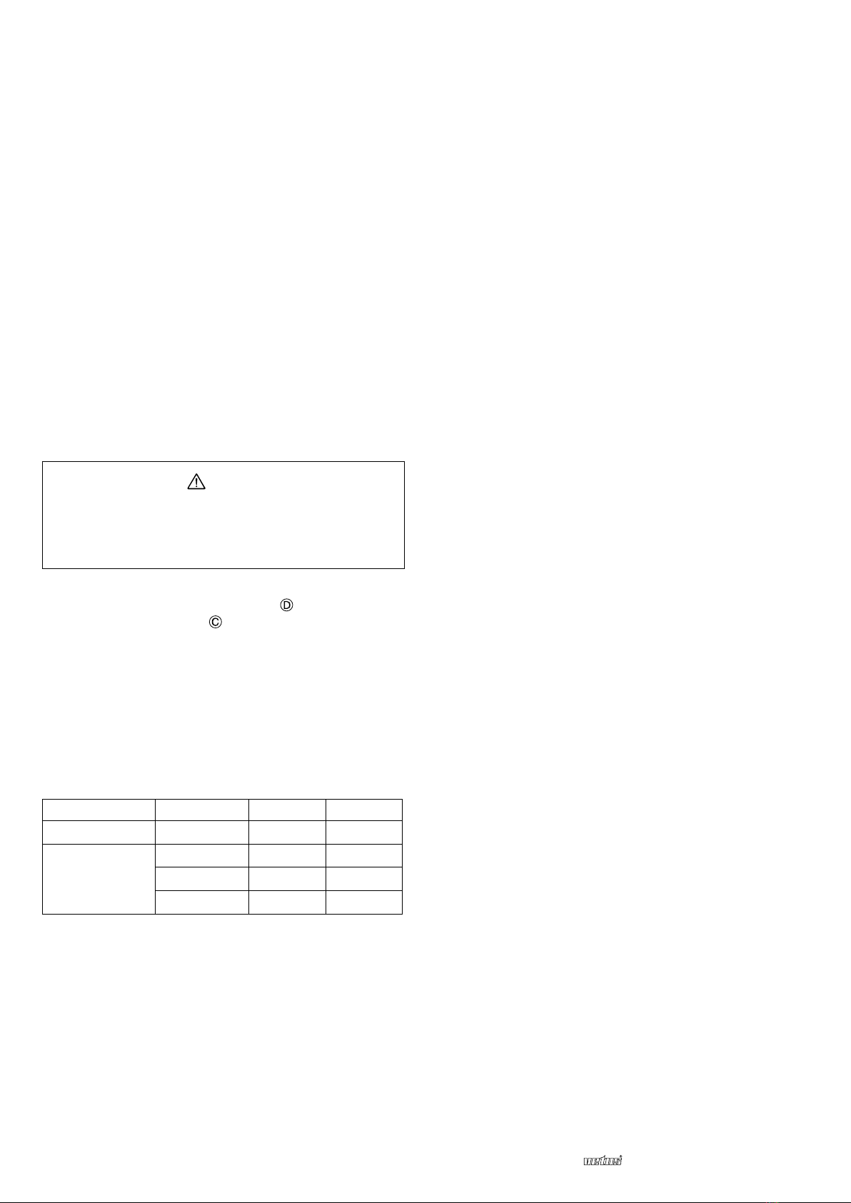
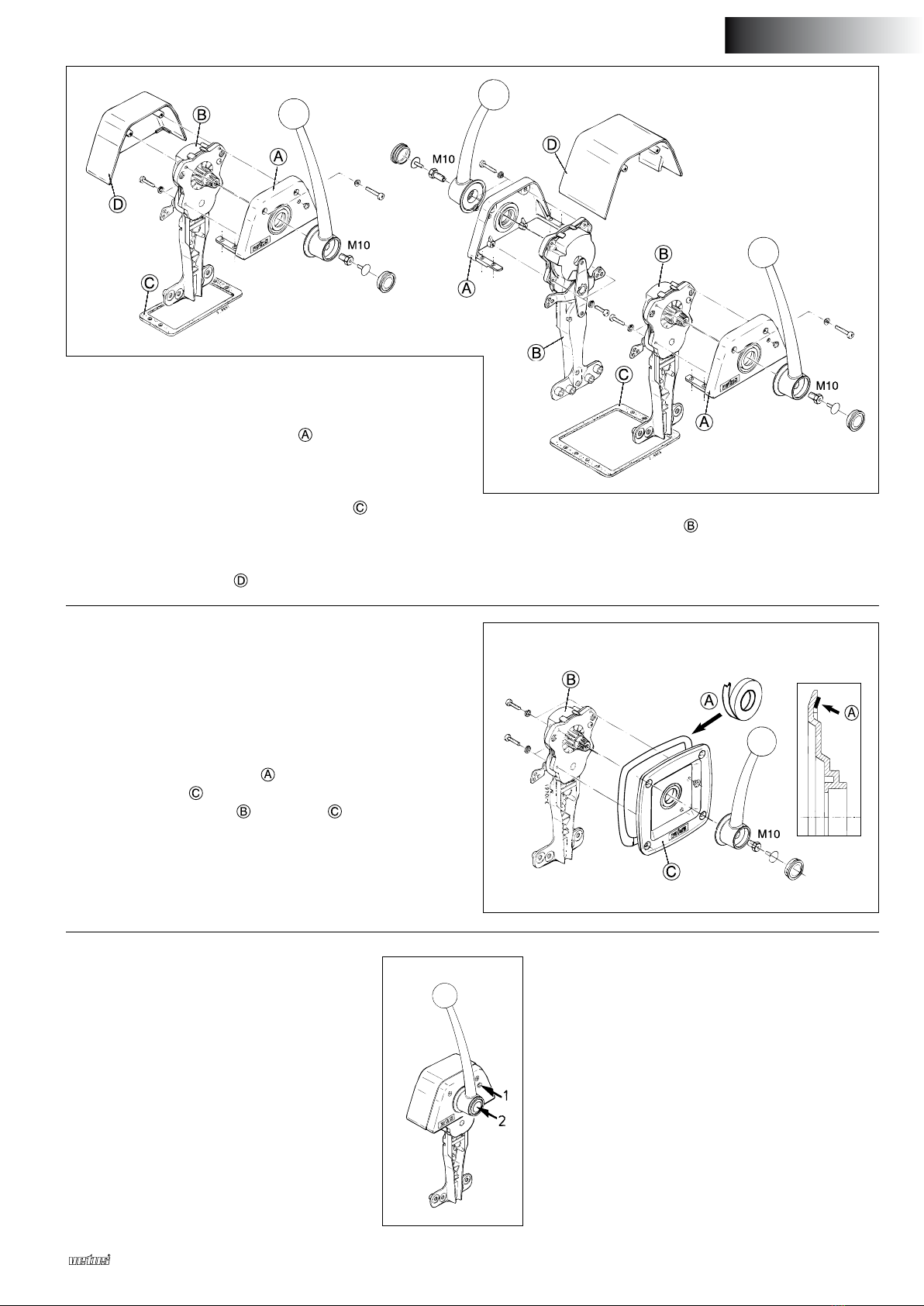
Retire siempre primero la palanca y la parte de la caja (en RCTOP..)
o la palanca y la chapa (en SI(S)CO(G)) del mecanismo, antes de
conectar los cables al mecanismo (véanse los dibujos en la página
de la derecha).
Además del tipo de cable 33C suministrado por Vetus y Morse, el
mecanismo también es adecuado para el tipo de cable OS de OMC
y el tipo de cable KM de Mercury.
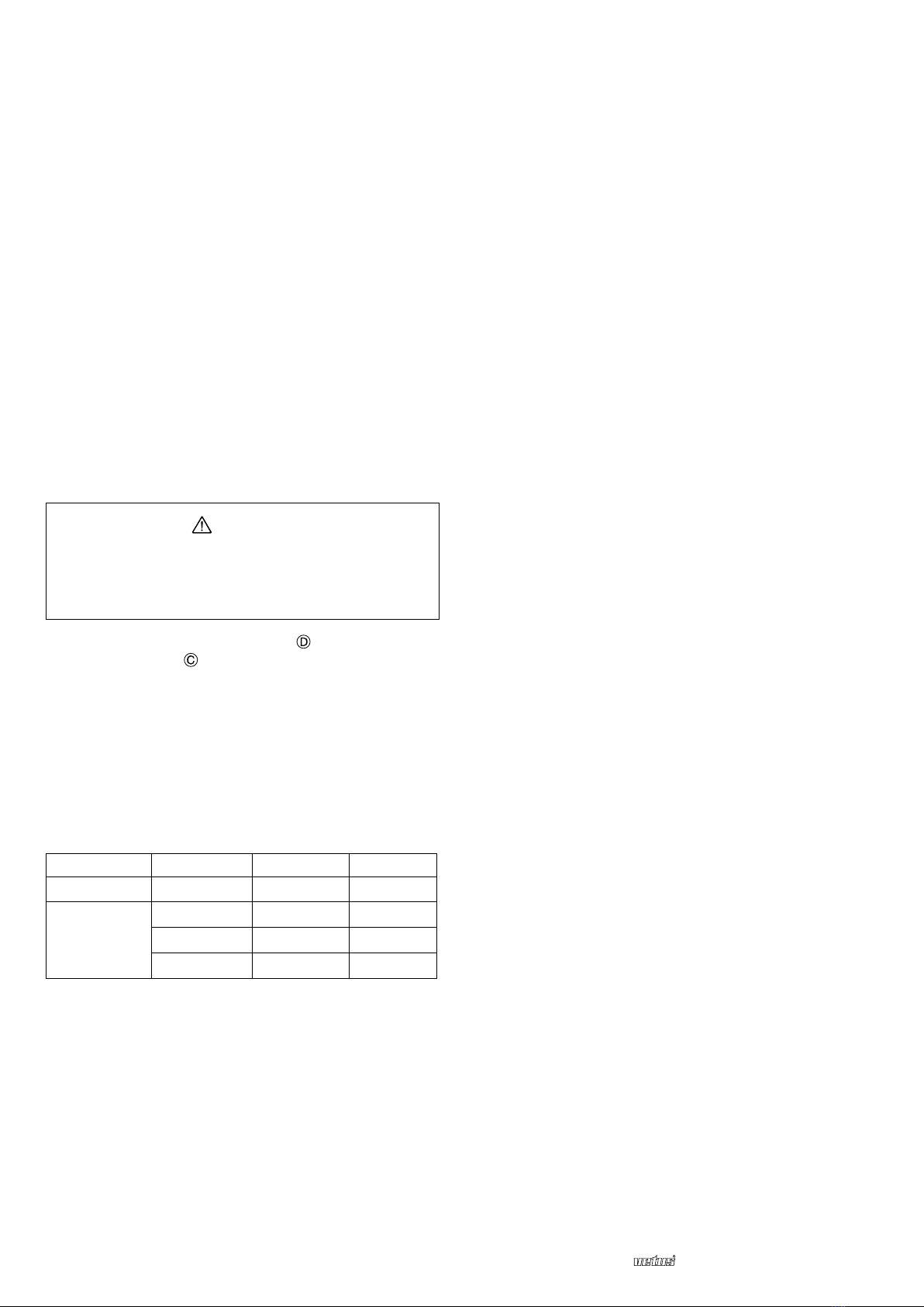
Los agujeros de fijación en el mecanismo están numerados. Estos
números corresponden con el tipo de cable:
Función Tipo de cable ‘Empujando’ ‘Tirando’
Dar gas Todos
Cambiar de
marcha (hacia
delante)
33C
OS
KM
Procure que ambas funciones del mecanismo estén en la posición
neutral antes de conectar los cables.
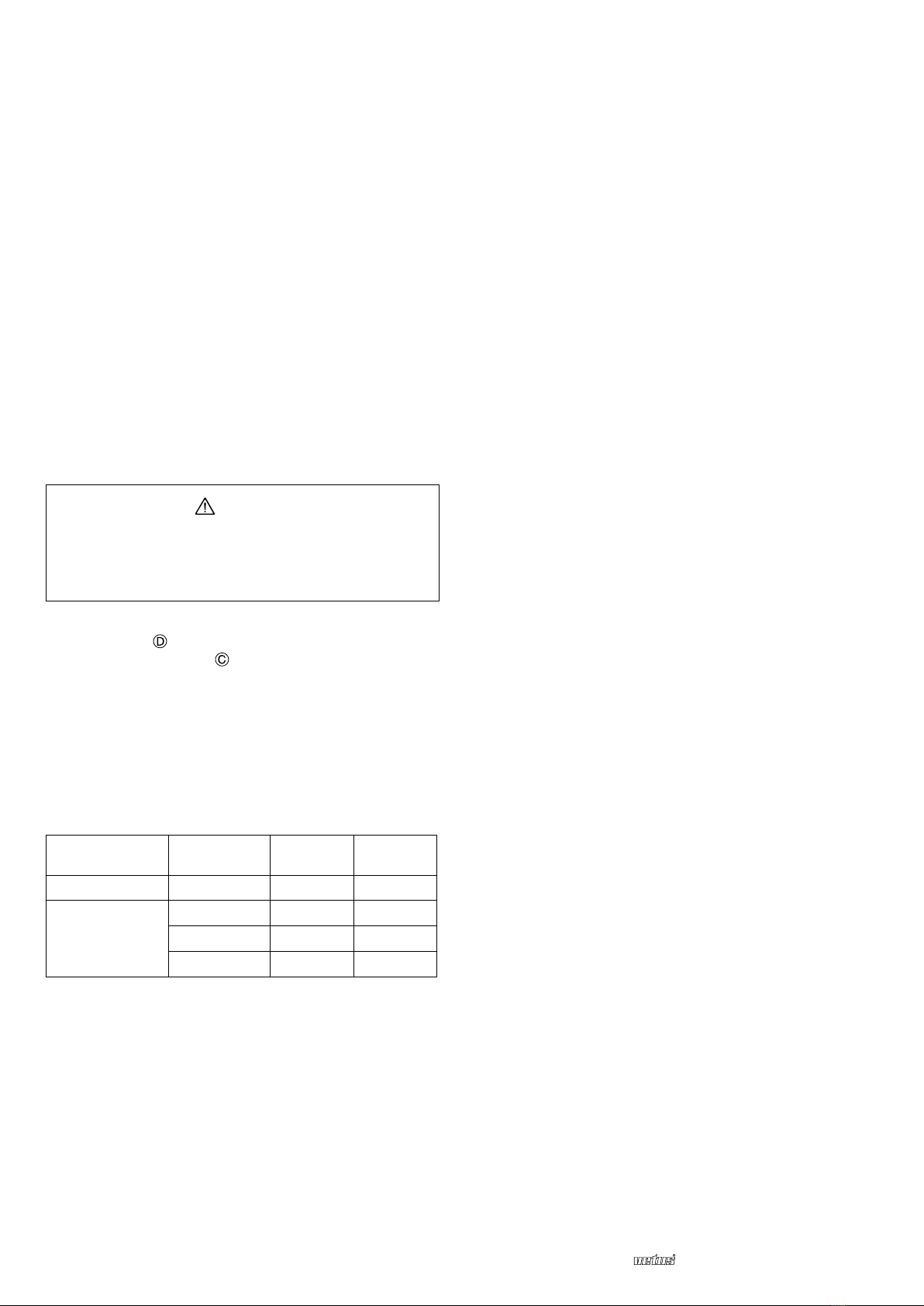
Conexión del cable del gas:
Dar gas ‘empujando’ : véase el dibujo 1 de la página 14
Dar gas ‘tirando’ : véase el dibujo 2 de la página 14
Conexión del cable del inversor:
Cambiar de marcha ‘empujando hacia delante’ y
‘tirando hacia atrás’: dibujo 3 de la página 14
Cambiar de marcha ‘empujando hacia atrás’y
‘tirando hacia delante’: dibujo 4 de la página 14
Al instalar los cables fíjese además en los siguientes puntos:
• Procure que la longitud (total) del cable sea adecuada.
• Instale el cable con un número de curvas tan pequeño como sea
posible y un radio de exión tan grande como sea posible (como
mínimo 500 mm).
• Los cables deben jarse con abrazaderas a distancias regulares
(cada 60 cm).
• No instale el cable demasiado cerca de fuentes de calor, como las
diferentes partes del sistema de escape.
• Evite el roce del cable.
• Después de la instalación, controle en el mecanismo si los cables
se pueden mover sin ofrecer resistencia considerable.
2.2 Cables de empuje-tracción en el motor
Conecte los cables con el inversor y la bomba de carburante tal y
como ha sido prescrito por el suministrador del motor.
Controle si la palanca de la bomba de carburante en el motor alcan-
za su posición final, cuando la palanca del mando a distancia se
pone en la posición límite.
Controle asimismo el funcionamiento adecuado del inversor.
2.3 Interruptor neutral
El mecanismo ya está provisto de un interruptor neutral. Este inte-
rruptor neutral impide que el motor se pueda arrancar cuando el
inversor todavía está conectado.
Si hace uso del interruptor neutral, éste debe conectarse tal y como
se indica en los esquemas eléctricos de la página 15.
2.4 Varios mandos a distancia
Cuando un motor está equipado con dos mandos a distancia, hay
que adquirir diferenciales.
Con diferenciales los dos mandos a distancia pueden ser conectados
entre sí, de modo que el motor pueda activarse desde dos lugares
independientes uno del otro.
Por motor hacen falta dos diferenciales: uno para el inversor y otro
para la bomba de carburante. Véase el dibujo de la página 15.
2.5 Caja y palanca
Al elegir el lugar donde se vayan a montar la caja y la palanca, tenga
en cuenta el ángulo máximo que puede hacer la palanca. Tenga en
cuenta asimismo la longitud total del mecanismo. Véase el dibujo
‘Dimensiones principales’.
ESPAÑOL

030606.07 11
Mechanical remote engine control
ESPAÑOL
Montaje superior:
• Dibuje los agujeros de fijación a taladrar y la apertura a serrar con
la ayuda de la plantilla suministrada.
• Las dos abrazaderas en la parte sirven de abrazaderas de
fijación. Controle si los agujeros de fijación corresponden con los
agujeros dibujados.
• Taladre los agujeros y sierre la apertura.
• Aplique correctamente la junta autoadhesiva suministrada .
• Monte el mando a distancia con tornillos M5 de la longitud
adecuada.
• Ahora monte la parte de la caja.
• Engrase el eje del mecanismo y monte la palanca en la
Montaje lateral:
El mando a distancia para montaje lateral necesita un espacio libre
de como mínimo 180 mm detrás del mamparo para poder montar
el conjunto.
• Dibuje los agujeros de fijación a taladrar y la apertura a serrar con
la ayuda de la plantilla suministrada.
• Taladre los agujeros y sierre la apertura.
• Aplique correctamente la junta autoadhesiva suministrada, en
la parte trasera de la chapa . Véase el detalle ampliado.
• Fije el mecanismo a la chapa .
• Ahora fije con tornillos el conjunto contra el mamparo.
• Engrase el eje del mecanismo y monte la palanca en la posición
deseada (en general verticalmente).
• Disponer en dichos tornillo M10 un medio de seguridad
(Loctite®243).
• Controle el paso de los cables.
5 Mantenimiento
• Si fuera necesario, limpie la palanca y la caja con agua
dulce.
• Controle regularmente el mecanismo para detectar
piezas sueltas y el desgaste de las partes móviles.
Engrase periódicamente las partes móviles con un
aceite lubricante hidrófugo.
• Controle con regularidad los cables y las conexiones
de los cables para detectar el desgaste y la corrosión.
3 Ajuste
Con el tornillo 1 se puede ajustar la fricción para el
mecanismo de gas, dependiendo de la contrapre-
sión de la bomba de carburante.
4 Activación
Con el pulsador 2 se puede desactivar el inversor, de
modo que solamente se pueda dar gas, por ejemplo
para arrancar y calentar el motor.
Cuando la palanca se pone de nuevo en la posición
neutral, vuelve a saltar el pulsador y el mando a
distancia está listo para el uso normal.
posición deseada (en general verticalmente).
•Disponer en dichos tornillo M10 un medio de seguridad
(Loctite®243).
• Controle el paso de los cables.

12 030606.07 Mechanical remote engine control
1 Introduzione
Con i telecomandi meccanici per motori Vetus è possibile comanda-
re con un’unica leva sia la frizione che la pompa del combustibile.
2 Installazione
2.1 Collegamento dei cavi di trazione/spinta al
meccanismo
Il meccanismo permette di comandare:
• La pompa del combustibile (acceleratore) - a ‘spinta’
- a ‘trazione’
• La frizione (cambio)
- a‘spinta per marcia avanti’ed a‘trazione per marcia indietro’
- a‘spinta per marcia indietro’ ed a‘trazione per marcia avanti’
Contattate il fornitore del motore in caso di dubbi circa il tipo di
comando dell’acceleratore e del cambio del motore (a ‘spinta’o a
‘trazione’).
attenzione!
Collegare sempre prima i cavi al meccanismo. I collegamenti
con la frizione e la pompa del combustibile vanno effettuati
solo dopo aver installato completamente il meccanismo.
Rimuovere sempre prima la leva e la parte della scatola (per i
modelli RCTOP..), o la leva ed il pannello (per il modello SI(S)
CO(G)), del meccanismo, prima di collegare i cavi al meccanismo
stesso (vedi disegno nella pagina successiva).
Oltre ai cavi tipo 33C, forniti dalla Vetus e dalla Morse, possono
essere impiegati anche cavi tipo OS della OMC e KM della Mercury.
I fori di innesto sul meccanismo sono numerati. La seguente tabella
riporta la corrispondenza tra il tipo di cavo ed il numero del foro.
Funzione Tipo di cavo a ‘spinta’ a ‘trazione’
Accelerazione Tutti
Cambio
(marcia avanti)
33C
OS
KM
Assicurarsi che entrambe le funzioni del meccanismo siano in folle
(posizione neutrale) prima di collegare i cavi.
Collegamento del cavo dell’acceleratore:
Acceleratore a ‘spinta’ : vedi figura 1 a pagina 14
Acceleratore a ‘trazione’ : vedi figura 2 a pagina 14
Collegamento del cavo della frizione:
Cambio a ‘spinta per marcia avanti’ e ‘trazione per marcia indietro’:
vedi figura 3 a pagina 14
Cambio a ‘spinta per marcia indietro’ e‘trazione per marcia avant’:
vedi figura 4 a pagina 14
Al fine di una corretta installazione è necessario che:
• la lunghezza (totale) dei cavi sia esatta;
• i cavi presentino meno curve possibile ed il raggio di curvatura sia
più ampio possibile (minimo 500 mm);
• i cavi siano sostenuti a distanza regolare (un sostegno ogni 60 cm);
• i cavi non vengano installati troppo vicino a fonti di calore, come
alle diverse parti del sistema di scarico;
• i cavi siano integri;
• dopo il collegamento al meccanismo, i cavi non oppongano trop-
pa resistenza al movimento.
2.2 Collegamento dei cavi di trazione/ spinta al
motore
Collegare i cavi alla frizione ed alla pompa del combustibile secondo
le modalità indicate dal fornitore del motore.
Controllare che la leva della pompa del combustibile sul motore
possa raggiungere la sua posizione limite, quando la leva dell’acce-
leratore è completamente aperta.
Verificare, inoltre, il corretto funzionamento della frizione.
2.3 Dispositivo di protezione
Il meccanismo è dotato di un dispositivo di protezione, che impedi-
sce che il motore possa essere avviato con la marcia innestata.
Qualora venga fatto uso di un dispositivo di protezione, collegare il
dispositivo secondo le indicazioni riportate nello schema elettrico a
pagina 15.
2.4 Installazione di più telecomandi
Se il motore è dotato di due telecomandi, devono essere installati dei
dispositivi differenziali.
I dispositivi differenziali permettono di collegare tra di loro i due
telecomandi, in modo che il motore possa essere governato da due
postazioni diverse.
Per ciascun motore sono necessari due dispositivi differenziali, uno
per la frizione ed uno per la pompa del combustibile. Vedi figura a
pagina 15.
2.5 Scatola e leva
Nella scelta del punto di installazione della scatola e della leva, tene-
re conto della corsa massima della leva, nonché della lunghezza tota-
le del meccanismo. Vedi la figura riportante le ‘dimensioni principali’.
ITALIANO

030606.07 13
Mechanical remote engine control
ITALIANO
Montaggio superiore:
• Con l’ausilio della sagoma fornita, segnare la posizione dei fori e
dell’apertura da praticare.
• Le due staffe della parte servono per fissare il meccanismo.
Controllare che i fori delle staffe corrispondano alle posizioni segnate.
• Praticare i fori con il trapano e praticare l’apertura segnata con una
sega.
• Applicare correttamente la guarnizione autoadesiva fornita .
• Montare il telecomando con bulloni M5 di lunghezza adeguata.
• Montare la parte della scatola.
• Lubrificare l’asse del meccanismo e montare la leva nella posi-
zione desiderata (generalmente verticale).
Montaggio laterale:
Il telecomando per montaggio laterale necessita di uno spazio libero di
minimo 180 mm dietro il tramezzo per il montaggio del meccanismo.
• Con l’ausilio della sagoma fornita, segnare la posizione dei fori e
dell’apertura da praticare.
• Praticare i fori con il trapano e praticare l’apertura segnata con
una sega.
• Applicare correttamente la guarnizione autoadesiva fornita
dietro al pannello . Vedi dettaglio in figura.
• Fissare il meccanismo al pannello .
• Fissare il tutto con dei bulloni al tramezzo.
• Lubrificare l’asse del meccanismo e montare la leva nella
posizione desiderata (generalmente verticale).
• Munire questi dadi M10 di un dispositivo di bloccaggio
(Loctite®243).
• Controllare il percorso dei cavi.
5 Manutenzione
• In caso di necessità, pulire la leva e la scatola con ac-
qua dolce.
• Ispezionare regolarmente il meccanismo per control-
lare che non vi siano parti allentate e che e parti in
movimento non siano usurate.
Lubricare regolarmente le parti in movimento con un
lubricante idrorepellente.
• Controllare regolarmente che i cavi ed i loro collega-
menti non siano usurati o corrosi.
3 Regolazione
L’attrito dell’acceleratore, che dipende dalla resi-
stenza opposta dalla pompa del combustibile, può
essere regolato mediante la vite 1.
4 Uso
Il pulsante 2 permette di escludere la frizione,
lasciando attiva la sola funzione di acceleratore.
Questa funzione viene usata, per esempio, per l’ac-
censione ed il riscaldamento del motore. Quando la
leva viene portata nuovamente in posizione neutra,
il pulsante viene rilasciato automaticamente ed il
telecomando può essere usato normalmente.
• Munire questi dadi M10 di un dispositivo di bloccaggio
(Loctite®243).
• Controllare il percorso dei cavi.

14 030606.07 Mechanical remote engine control
1 2
3 4
Aansluitschema

030606.07 15
Mechanical remote engine control
6 Elektrisch schema’s
Electrical circuit diagrams
Elektrischer Schaltpläne
Schémas électrique
Esquemas eléctricos
Schemi elettrici
NEDERLANDS
ENGLISH FRANÇAIS ITALIANO
DEUTSCH ESPAÑOL
A Enkele bedieningsstuurstand
B Twee bedieningsstuurstanden
C Enkele bedieningsstuurstand met
herstart beveiliging
D Twee bedieningsstuurstanden met
herstart beveiliging
Startslot
Relais
Neutraal schakelaar
Startrelais
Laadcontrole lamp
Dynamo (Aansluiting D+/ WL)
7 Differentiaal apparaat
Differential device
Differenzial
Différentiel
Diferencial
Dispositivo differenziale
A Commande mono levier
B Commande double levier
C Commande mono levier avec pro-
tection anti-redémarrage
D Commande double levier avec pro-
tection anti-redémarrage
Verrou de démarrage
Relais
Sécurité point mort
Relais de démarrage
Témoin de contrôle de charge
Dynamo (Branchement D+/WL)
A B C D
voor brandstofpomp
for throttle
für Treibstoffpumpe
pour l’accélérateur
para la bomba de carburante
per pompa del combustibile
voor keerkoppeling
for gearbox
für Wendegetriebe
pour l’inverseur
para el inversor
per frizione
A Single command station
B Two command stations
C Single command station with
restart protection
D Two command stations with restart
protection
Starter switch
Relay
Neutral switch
Starter relay
Charging light
Alternator (Connection D+/ WL)
A Einzelbedienungssteuerstand
B Doppelbedienungssteuerstand
C Einzelbedienungssteuerstand mit
Neustartsicherung
D Doppelbedienungssteuerstand mit
Neustartsicherung
Zündschloss
Relais
Leerlaufschalter
Zündrelais
Vorglüh-Kontrolllampe
Dynamo (Anschluss D+/WL)
A Única posición de navegación para activación
B Dos posiciones de navegación para activación
C Única posición de navegación para
activación con protector de rearranque
D Dos posiciones de navegación para activa-
ción con protector de rearranque
Dispositivo de arranque
Relé
Interruptor neutral
Relé de arranque
Lámpara de control de carga
Dinamo (Conexión D+/WL)
A Posizione di governo singolo
B Posizione di governo doppio
C Posizione di governo singolo con disposi-
tivo di protezione di riavviamento
D Posizione di governo doppio con disposi-
tivo di protezione di riavviamento
Contatto a chiave
Relè
Dispositivo di protezione
Relè di avviamento
Spia di carica
Dinamo (Collegamento D+/WL)

vetusb. v. FOKKERSTRAAT 571 - 3125 BD SCHIEDAM - HOLLAND
TEL.: +31(0)88 4884700 - sales@vetus.nl - www.vetus.com
Printed in the Netherlands
030606.07 2021-01
8 Hoofdafmetingen
Principal dimensions
Hauptabmessungen
Dimensions principales
Dimensiones principales
Dimensioni principali
200 (7 7/8”)
179 (7 1/16”)
208 (8 3/16”) 87 (3 7/16”)
162 (6 3/8”) 71 (2 13/16”)
104 (4 1/8”)
237 (9 5/16”)
216 (8 1/2”)
200 (7
7
/
8
”)
134 (5
1
/
4
”)
RCTOPB
RCTOPTB
RCTOPBG
RCTOPSG
RCTOPTB
RCTOPTS
179 (7
1
/
16
”)
200 (7
7
/
8
”)244 (9
5
/
8
”)
122 (4
13
/
16
”)
142 (5
9
/
16
”)
85 (3
3
/
8
”)
45 (1
3
/
4
”)
MAX. 16 (
5
/
8
”)
MIN. 180
(7
1
/
16
”)
68
(2
11
/
16
”)
MAX. 16 (
5
/
8
”)
MIN. 180
(7
1
/
16
”)
98 (3
7
/
8
”)
28 (1
1
/
8
”)
68
(2
11
/
16
”)
127 (5”)
200 (7
7
/
8
”)244 (9
5
/
8
”)
147 (5
13
/
16
”)
179 (7
1
/
16
”)
SICO
SICOG
194 (7 5/8”)
194 (7 5/8”)
35°
95°
35°
95°
N
FR
200 (7 7/8”)
200 (7 7/8”)
35°
95°
35°
95°
N
FR
RCTOPB
RCTOPBG
RCTOPTB
RCTOPTBG
RCTOPS
RCTOPSG
RCTOPTS
RCTOPTSG
SISCO
SISCOG
SICO
SISCO
SICO
SICOG
SISCO
SISCOG
RCTOPTBG
RCTOPTSG
SICOG
SISCOG
Other manuals for RCTOPB
1
This manual suits for next models
11
Table of contents
Languages:
Other Vetus Remote Control manuals