Vetus HATO12C User manual

NEDERLANDS 5
ENGLISH 11
DEUTSCH 17
FRANÇAIS 23
ESPAÑOL 29
ITALIANO 35
110128.11
Copyright © 2023 VETUS B.V. Schiedam Holland
Installatie- en gebruikershandleiding
Elektrisch scheepstoilet
Installation and user manual
Electric marine toilet
Installations- und Benutzerhandbuch
Elektrische Schistoilette
Manuel d’Installation et d’utilisation
Toilette électrique marine
Manual de instalación y usuario
Inodoro marino eléctrico
Manuale d'installazione e d'uso
WC elettrico per settore marittimo
Electric marine toilet
HATO12C - HATO24C - HATO110C - HATO230C
Installation and user manual

2110128.11 Installation manual HATO_C electric marine toilet
Zorg er voor dat de eigenaar van het schip over deze handleiding kan beschikken.
Make sure that the user of the vessel is supplied with the owner’s manual.
Sorgen Sie dafür, daß dem Schiseigner die Gebrauchsanleitung bereitgestellt wird.
Veillez à ce que le propriétaire du bateau puisse disposer du mode d’emploi.
Asegurarse de que el propietario de la embarcación puede disponer de las instrucciones para el usuario.
Assicurarsi che il proprietario dell’imbarcazione disponga del manuale.
Sørg for, at denne brugsanvisning er til rådighed for skibets ejer.
Se till att båtens ägare har tillgång till bruksanvisningen.
Sørg for at skipets eier kan disponere over bruksanvisningen.
Käyttöohje tulee olla alusta käyttävien henkilöiden käytettävissä.
Upewnić się, że użytkownik statku jest zaopatrzony w instrukcję obsługi.
FR

110128.11 3
Installation manual HATO_C electric marine toilet
1 Veiligheid .................................. 5
2 Inleiding .................................... 5
3 Installatie................................... 5
3.1 Installatie van het frame ............... 5
3.2 Elektrische installatie.................... 6
3.2.1 12 V of 24 V systeem................ 6
3.2.2 Bedieningspaneel (12 V / 24 V).. 6
3.2.3 110 V of 230 V syteem.............. 6
3.3 Watertoevoer.............................. 6
3.4 Vuilwaterafvoer........................... 7
3.5 Voorkom hevelen ........................ 7
3.6 Montage voorzetwand................. 7
3.7 Aansluiten 12/24 Volt uitvoering 7
3.7.1 Afvoer ................................... 7
3.8 Aansluiten 120/230 Volt uitvoering 8
3.8.1 Afvoer ................................... 8
3.8.2 Slangaansluiting ..................... 8
3.9 Toe- en afvoeraansluitingen.......... 8
3.9.1 Afvoerslang (algemeen)........... 8
3.9.2 Toevoerslang.......................... 8
3.10 Montage van de toiletpot ............. 8
3.11 Testen........................................ 8
3.12 Eindmontage.............................. 8
4 Gebruik ..................................... 9
4.1 Winterklaar maken. . . . . . . . . . . . . . . . . . . . . . . 9
5 Onderhoud ................................ 9
6 Technische gegevens ................ 10
7 Storingzoeken.......................... 10
Inhoud Content Inhalt
1 Safety...................................... 11
2 Introduction............................. 11
3 Installation............................... 11
3.1 Installing the frame.................... 11
3.2 Electrical installation .................. 12
3.2.1 12 V or 24 V system................ 12
3.2.2 Control panel (12 V / 24 V) ...... 12
3.2.3 110 V or 230 V sytem ............. 12
3.3 Water supply............................. 12
3.4 Wastewater disposal .................. 13
3.5 Prevent siphoning ..................... 13
3.6 Mounting a false wall ................. 13
3.7 Connecting 12/24 Volt version..... 13
3.7.1 Outlet.................................. 13
3.8 Connecting 120/230 Volt version . 14
3.8.1 Discharge ............................ 14
3.8.2 Hose connection................... 14
3.9 Inlet and outlet connections ....... 14
3.9.1 Outlet (general) .................... 14
3.9.2 Supply hose ......................... 14
3.10 Mounting the toilet bowl............ 14
3.11 Testing ..................................... 14
3.12 Final assembly. . . . . . . . . . . . . . . . . . . . . . . . . . . 14
4 Use.......................................... 15
4.1 Winterising ............................... 15
5 Maintenance ............................ 15
6 Technical data .......................... 16
7 Troubleshooting....................... 16
8 Hoofdafmetingen..................... 41
9 Installatievoorbeeld.................. 42
10 Aansluitschema’s ...................... 43
8 Principal dimensions................. 41
9 Installation example ................. 42
10 Wiring diagrams ....................... 43
1 Sicherheitsbestimmungen
........ 17
2 Einleitung ................................ 17
3 Einrichtung .............................. 17
3.1 Aufstellen des Rahmens ............. 17
3.2 Elektrischer Anschluss ................ 18
3.2.1 12-V- oder 24-V-Netz ............. 18
3.2.2 Schalttafel (12 V / 24 V) .......... 18
3.2.3 110-V- oder 230-V-Netz.......... 18
3.3 Wasserversorgung..................... 18
3.4 Entsorgung des Abwassers ......... 19
3.5 Siphonbildung verhindern.......... 19
3.6 Montage einer Zwischenwand .... 19
3.7 Anschluss der 12/24-Volt-Version. 19
3.7.1 Auslass ................................ 19
3.8 Anschluss 120/230 Volt Version.... 20
3.8.1 Abuss ................................ 20
3.8.2 Schlauchanschluss ................ 20
3.9 Einlass- und Auslassanschlüsse.... 20
3.9.1 Auslass (allgemein) ............... 20
3.9.2 Zulaufschlauch ..................... 20
3.10 Montage des Toilettenbeckens .... 20
3.11 Prüfung.................................... 20
3.12 Endmontage............................. 20
4 Benutzung ............................... 21
4.1 Überwinterung ......................... 21
5 Wartung .................................. 21
6 Technische Daten ..................... 22
7 Störungen................................ 22
8 Hauptabmessungen ................. 41
9 Montagebeispiel ...................... 42
10 Schaltplan................................ 43

4110128.11 Installation manual HATO_C electric marine toilet
Sommaire Índice Indice
1 Sécurité .................................. 23
2 Introduction............................. 23
3 Installation............................... 23
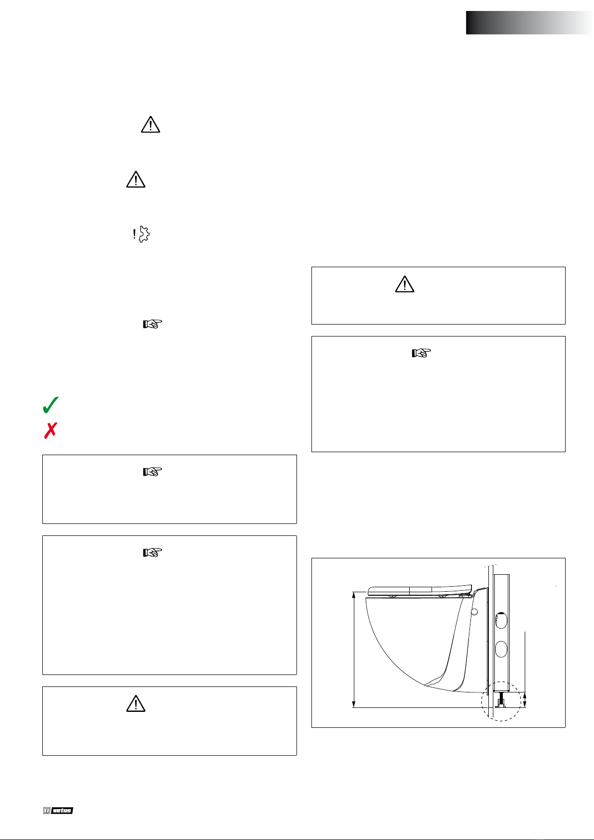
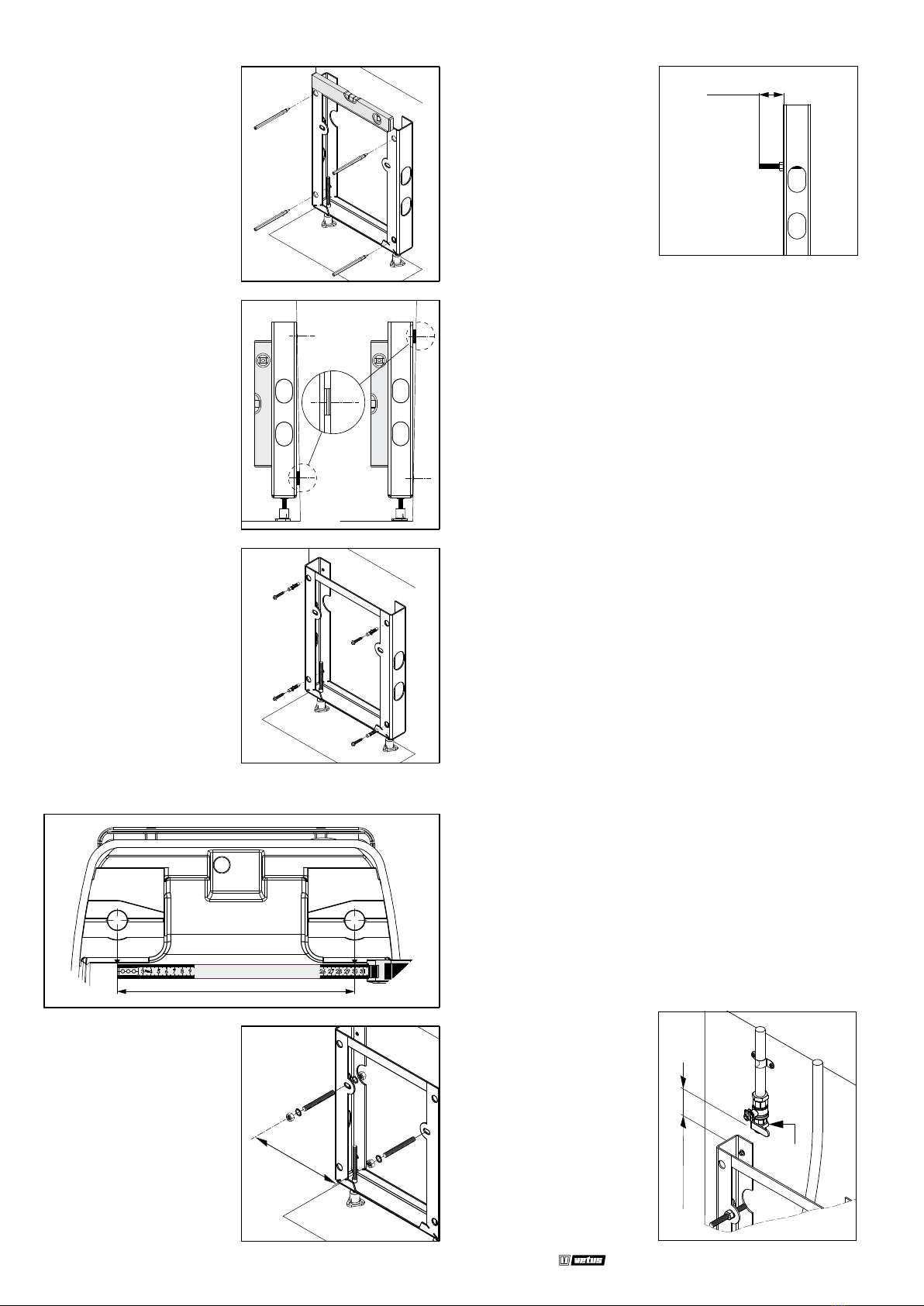
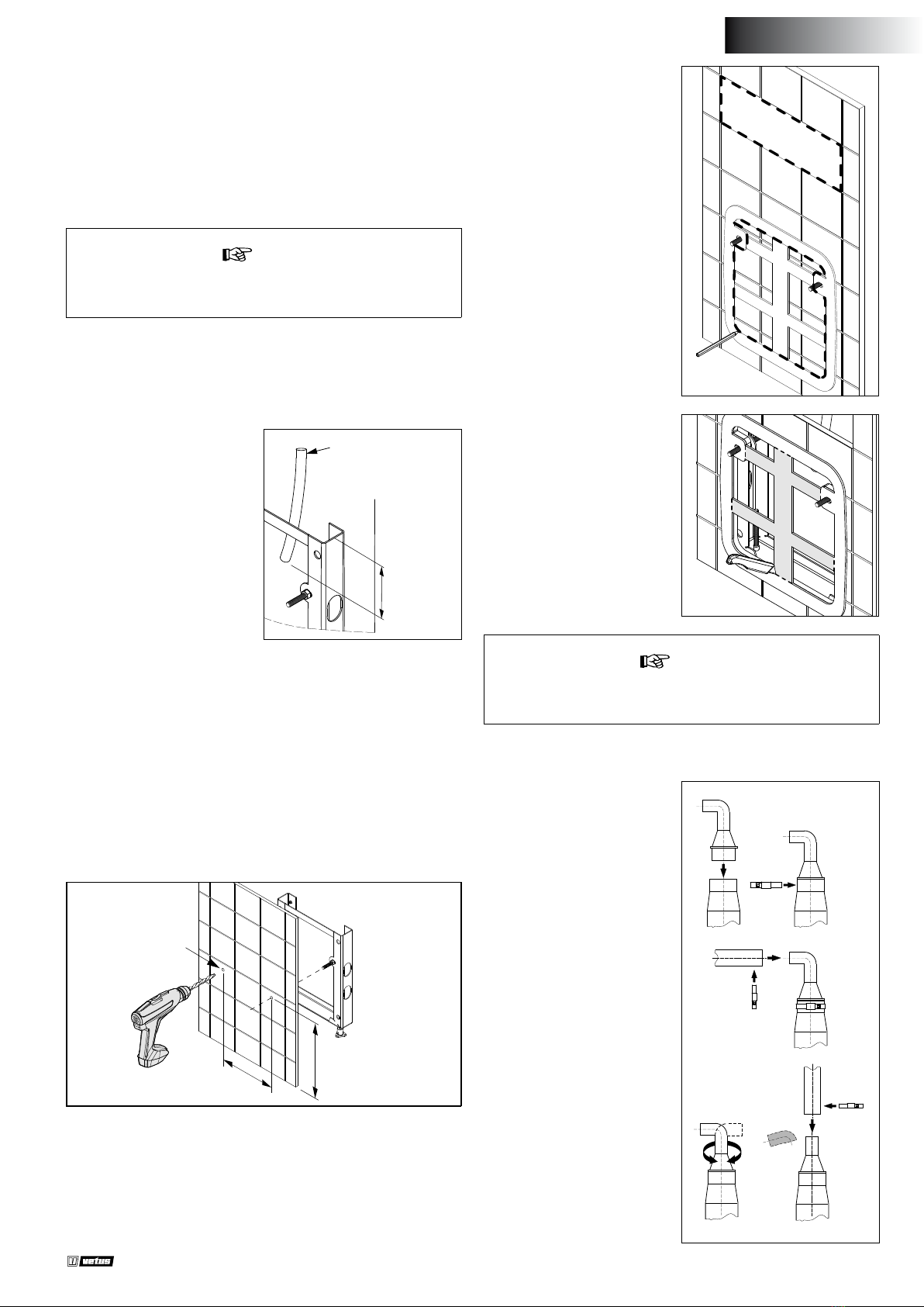
3.1 Installation du cadre .................. 23
3.2 Installation électrique ................ 24
3.2.1 Système de 12 V ou 24 V. . . . . . . . . 24
3.2.2 Panneau de commande
(12 V / 24 V).......................... 24
3.2.3 Système de 110 V ou 230 V..... 24
3.3 Alimentation en eau .................. 24
3.4 Élimination des eaux usées ......... 25
3.5 Prévention du siphonnage.......... 25
3.6 Montage d'un faux mur.............. 25
3.7 Version de raccordement de 12/24
volts ........................................ 25
3.7.1 Sortie .................................. 25
3.8 Version de raccordement de
120/230 Volts ............................ 26
3.8.1 Drain................................... 26
3.8.2 Raccordement du tuyau......... 26
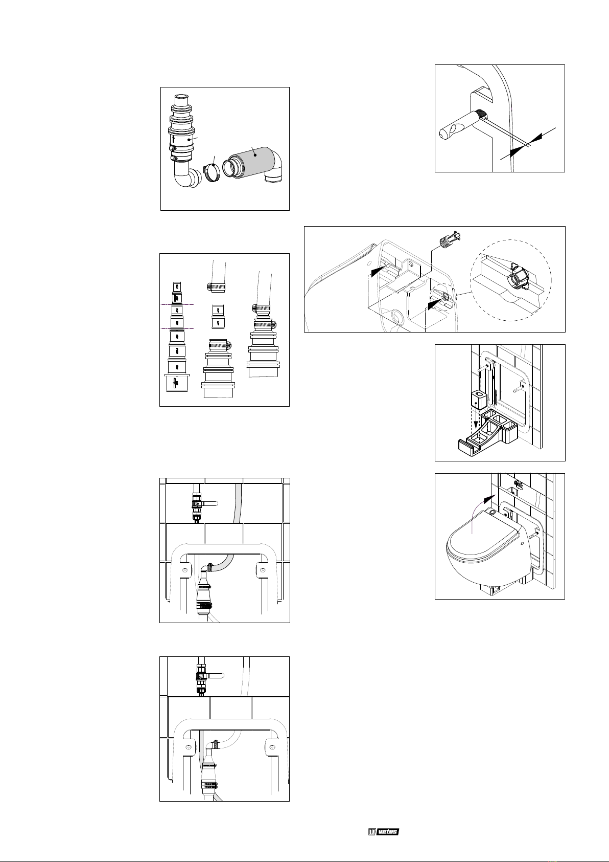
3.9 Raccords d'entrée et de sortie ..... 26
3.9.1 Sortie (Généralités)................ 26
3.9.2 Tuyau d'alimentation............. 26
3.10 Montage de la cuvette des toilettes 26
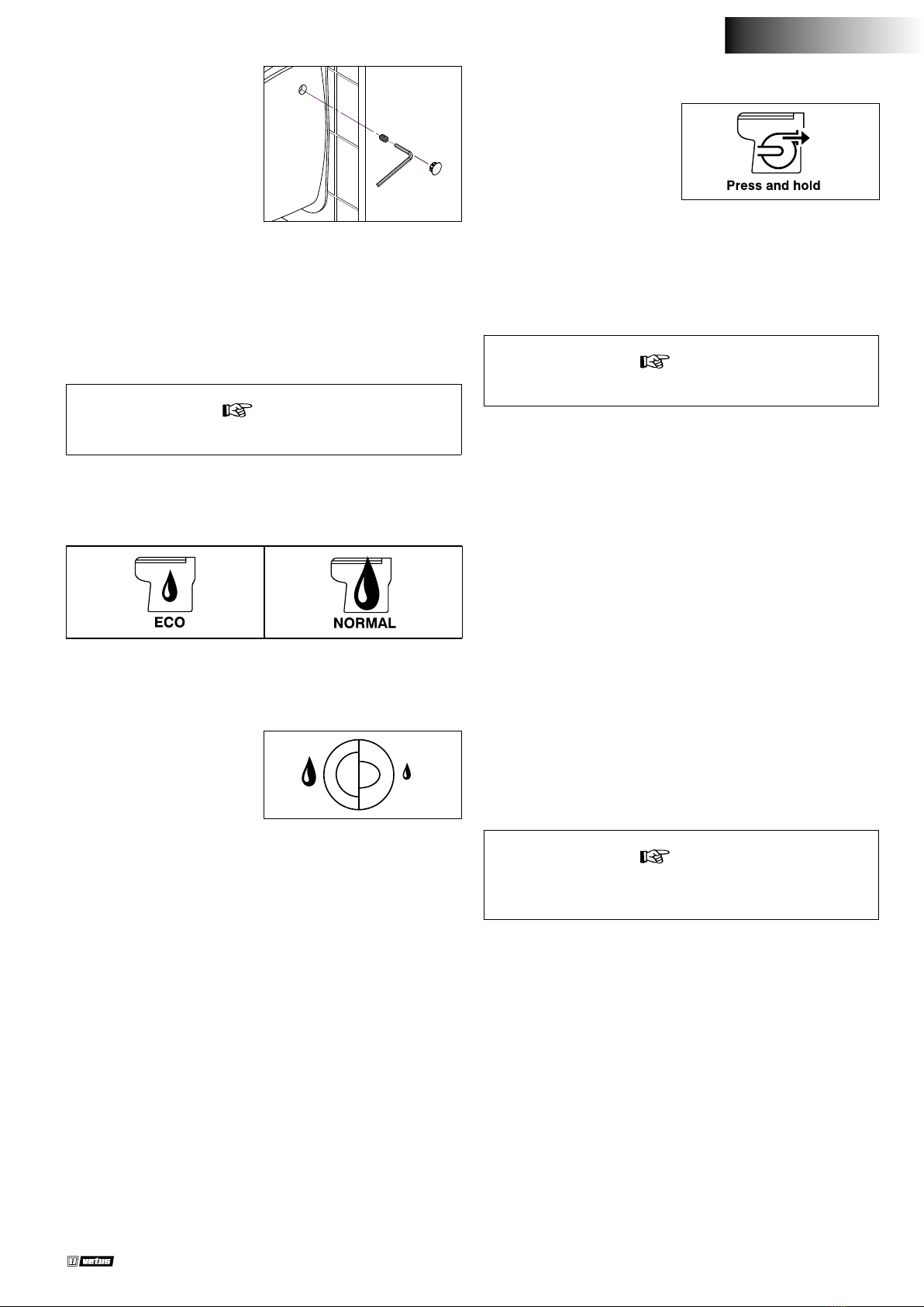
3.11 Essai ........................................ 26
3.12 Montage nal ........................... 26
4 Utilisation ................................ 27
4.1 Hivernage. . . . . . . . . . . . . . . . . . . . . . . . . . . . . . . . . 27
5 Entretien.................................. 27
6 Renseignements techniques...... 28
7 Recherche de pannes................ 28
1 Seguridad................................ 29
2 Introducción ............................ 29
3 Instalación ............................... 29
3.1 Instalación del marco ................. 29
3.2 Instalación eléctrica ................... 30
3.2.1 Sistema de 12 V o 24 V ........... 30
3.2.2 Panel de control (12 V / 24 V) .. 30
3.2.3 Sistema de 110 V o 230 V........ 30
3.3 Suministro de agua.................... 30
3.4 Sistema municipal
de alcantarillado........................ 31
3.5 Prevenir el sifón......................... 31
3.6 Montaje de una pared falsa......... 31
3.7 Versión de conexión de 12/24
voltios...................................... 31
3.7.1 Salida .................................. 31
3.8 Versión de 120/230 voltios de
conexión .................................. 32
3.8.1 Desagüe .............................. 32
3.8.2 Conexión de la manguera ...... 32
3.9 Conexiones de entrada y salida ... 32
3.9.1 Salida (general)..................... 32
3.9.2 Manga de repuesto ............... 32
3.10 Montaje del inodoro .................. 32
3.11 Prueba ..................................... 32
3.12 Montaje nal. . . . . . . . . . . . . . . . . . . . . . . . . . . . . 32
4 Uso. . . . . . . . . . . . . . . . . . . . . . . . . . . . . . . . . . . . . . . . . . 33
4.1 Invernalización.......................... 33
5 Mantenimiento ........................ 33
6 Especicaciones técnicas........... 34
7 Averías .................................... 34
1 Sicurezza ................................. 35
2 Introduzione ............................ 35
3 Installazione ............................ 35
3.1 Installare il telaio ....................... 35
3.2 Impianto elettrico...................... 36
3.2.1 Impianto da 12 V o 24 V ......... 36
3.2.2 Pannello di controllo
(12 V / 24 V).......................... 36
3.2.3 Impianto da 110 V o 230 V ...... 36
3.3 Erogazione acqua ...................... 36
3.4 Smaltimento delle acque reue ... 37
3.5 Impedire il sifonamento ............. 37
3.6 Montaggio di una controparete... 37
3.7 Collegamento versione 12/24 Volt 37
3.7.1 Presa ................................... 37
3.8 Collegamento versione
120/230 Volt ............................. 38
3.8.1 Scarico ................................ 38
3.8.2 Collegamento dei tubi........... 38
3.9 Connessioni ingresso e uscita...... 38
3.9.1 Uscita (generale)................... 38
3.9.2 Tubo di alimentazione ........... 38
3.10 Montare il water ........................ 38
3.11 Collaudo .................................. 38
3.12 Montaggio nale....................... 38
4 Funzionamento ........................ 39
4.1 Preparazione all’inverno ............. 39
5 Manutenzione.......................... 39
6 Dati tecnici............................... 40
7 Guasti...................................... 40
8 Dimensiones principales ........... 41
9 Ejemplo de instalación.............. 42
10 Capacidad de las baterías, cables
de baterías............................... 43
8 Dimensions principales ............. 41
9 Exemple d’installation............... 42
10 Capacité de la batterie, câbles
de batterie ............................... 43
8 Dimensioni principal................. 41
9 Esempio di installazione ........... 42
10 Batterikapacitet, cavi della
batteria ................................... 43

110128.11 5
Installation manual HATO_C electric marine toilet
1 Veiligheid
Waarschuwingsaanduidingen
Indien van toepassing worden in deze handleiding in verband met
veiligheid de volgende waarschuwingsaanduidingen gebruikt:
Gevaar
Geeft aan dat er een groot potentieel gevaar aanwezig is dat ernstig
letsel of de dood tot gevolg kan hebben.
WaarschuWinG
Geeft aan dat er een potentieel gevaar aanwezig is dat letsel tot ge-
volg kan hebben.
voorzichtiG
Geeft aan dat de betreende bedieningsprocedures, handelingen,
enzovoort, letsel of fatale schade aan de machine tot gevolg kunnen
hebben. Sommige VOORZICHTIG-aanduidingen geven tevens aan
dat er een potentieel gevaar aanwezig is dat ernstig letsel of de dood
tot gevolg kan hebben.
Let op
Legt de nadruk op belangrijke procedures, omstandigheden, enzo-
voort.
Symbolen
Geeft aan dat de betreende handeling moet worden uit-
gevoerd.
Geeft aan dat een bepaalde handeling verboden is.
Let op
Algemene regels en wetten met betrekking tot veiligheid en
het lozing van vuilwater dienen altijd in acht te worden ge-
nomen!
Let op
Dit apparaat kan worden gebruikt door kinderen vanaf 8 jaar
en door personen met lichamelijke, zintuiglijke of verstan-
delijke beperking of door mensen zonder ervaring of kennis,
mits zij onder correct toezicht staan of instructies voor het
veilige gebruik van het apparaat hebben gekregen en zij de
risico’s hebben begrepen. Kinderen mogen niet met het ap-
paraat spelen. De schoonmaak en het onderhoud van het ap-
paraat door de gebruiker mag niet zonder toezicht door kin-
deren worden gedaan.
WaarschuWinG
Indien de voedingskabel beschadigd is, dient deze om gevaar
te voorkomen, te worden vervangen door de fabrikant, de
klantenservice of mensen met soortgelijke bevoegdheden.
NEDERLANDS
2 Inleiding
Deze handleiding geeft richtlijnen voor de inbouw van het VETUS
HATO_C elektrisch scheepstoilet.
Het toilet is voorzien van een geïntegreerd vermaalsysteem. Bij cor-
recte installatie en gebruik functioneert de HATO_C als een normaal
wal-toilet.
De kwaliteit van de inbouw is maatgevend voor de betrouwbaarheid
van het systeem. Bijna alle storingen die naar voren komen zijn te-
rug te leiden tot fouten of onnauwkeurigheden bij de inbouw. Het
is daarom van het grootste belang de in de installatieinstructies ge-
noemde punten tijdens de inbouw volledig op te volgen en te con-
troleren.
Eigenmachtige wijzigingen sluiten de aansprakelijkheid van de
fabriek voor de daaruit voortvloeiende schade uit.
WaarschuWinG
Werk nooit aan de elektrische installatie terwijl het systeem
onder spanning staat.
Let op
Het toilet mag alleen gebruikt worden voor het vermalen en
afvoeren van faecaliën en toiletpapier.
Het toilet is niet geschikt voor het vermalen van voorwerpen
zoals watten, tampons, maandverband, condooms en haren,
of het wegpompen van vloeistoen zoals olie. Dit kan schade
veroorzaken!
3 Installatie
3.1 Installatie van het frame
Stel, met behulp van de verstelbare poten, de hoogte van de toilet-
pot in.
430 - 520 mm
35 - 125 mm
Plaats het frame tegen de wand waaraan het toilet wordt opgehan-
gen. Gebruik indien nodig de verstelbare poten om het frame hori-
zontaal te zetten (gebruik een waterpas).

6110128.11 Installation manual HATO_C electric marine toilet
Teken met behulp van een pot-
lood de 4 bevestigingsgaten
van het frame af en boor deze
met de juiste diameter.
Gebruik indien nodig ringen
aan de boven- of onderkant van
het frame om ervoor te zorgen
dat het frame verticaal staat
(gebruik een waterpas).
Bevestig het frame aan de
wand. Gebruik hiervoor, afhan-
kelijk van de ondergrond, de
juiste bevestigingsmiddelen
(niet meegeleverd).
Meet de steekmaat (A1) van de toiletpot op.
A1
Stel de steekmaat (A2) van het
frame zo in dat deze gelijk is aan
de steekmaat (A1) van de toilet-
pot.
A2
Bevestig de draadeinden met
behulp van de moeren en borg-
ringen (meegeleverd) op het
frame.
Let op: laat de draadeinden 65
mm uitsteken.
65 mm
3.2 Elektrische installatie
3.2.1 12 V of 24 V systeem
• Controleer of de spanning, vermeld op het typeplaatje van de mo-
tor, overeenkomt met de boordspanning.
• Gebruik accu’s met voldoende capaciteit om een correcte werking
van het toilet te verkrijgen.
• Sluit de voedingsspanning aan zoals in het aansluitschema is aan-
gegeven, zie pagina 43.
• Plaats een schakelaar en zekering in de plus (‘+’) draad (25A@12V
& 15A@24V).
• Pas draden toe met een minimale doorsnede van 6 mm2(bij 12 V)
of 4 mm2(bij 24 V).
3.2.2 Bedieningspaneel (12 V / 24 V)
• Monteer de inbouwens met de pakking in de wand. Voor gataf-
metingen zie pagina 41.
• Voer de kabel door de ens naar het toilet en verbind deze met
de kabel op het toilet. Breng ter bescherming de meegeleverde
behuizing aan over de stekerverbinding.
• Klik het paneel in de inbouwens. Let er op dat de pakking correct
gemonteerd is.
3.2.3 110 V of 230 V syteem
• Sluit de voedingsspanning aan zoals in het aansluitschema is aan-
gegeven.
• Gebruik een dubbelpolige schakelaar en plaats een dubbelpolige
installatieautomaat (in de fase- en nul draad).
3.3 Watertoevoer
Gebruik koperen leidingen of slangen voor de watertoevoer.
Voorzie de watertoevoer van
een kogelkraan met een aan-
sluiting van 3/4”uitwendig.
Zorg er voor dat de aansluiting
zich circa 150 mm boven het
frame bevindt en de kogelkraan
bereikbaar blijft.
Zet de toevoer stevig vast met
klemmen.
G 3/4
150 mm
+/-

110128.11 7
Installation manual HATO_C electric marine toilet
NEDERLANDS
Als er aan boord een waterdruksysteem geïnstalleerd is, kan de toe-
voerslang op dit systeem worden aangesloten. De waterdruk moet
minimaal 1,7 bar zijn om een optimale spoeling te verkrijgen.
Als de druk van het waterdruksysteem minder is dan 1,7 bar of wan-
neer buitenwater wordt gebruikt als spoelwater, installeer dan een
water toevoerpomp in de toevoerslang. De capaciteit van de water
toevoerpomp dient minimaal 10 liter/minuut te zijn.
Let op
Wanneer buitenwater als spoelwater wordt gebruikt, zorg er
dan voor dat dit water zeer goed gelterd wordt!
3.4 Vuilwaterafvoer
Gebruik als afvoerleiding slang ø 19 mm (bijvoorbeeld ‘VETUS geur-
dichte vuilwaterslang’ ø 19 mm).
Kort de afvoer in tot circa 200
mm onder het frame.
Zet de afvoer vast met klem-
men.
ø 19 mm
+/- 200 mm
3.5 Voorkom hevelen
Indien het toilet zich onder of minder dan 50 cm boven de waterlijn
bevindt, bestaat het gevaar dat water (toevoer of afvoer) door de he-
velwerking in het toilet kan terugstromen.
Om dit hevelen te voorkomen dient op het hoogste punt in de toe-
voer en/of afvoer een beluchter geplaatst te worden. Zie pagina 42
voor enkele installatievoorbeelden.
3.6 Montage voorzetwand
A2
375 - 465mm
Ø 12 mm
Plaats de voorzetwand (b.v. gipsplaat) tegen het frame.
Boor op de juiste plaats 2 gaten, ø 12 mm, door de voorzetwand, zo-
dat deze volledig tegen het frame rust.
Voorzie de voorzetwand van
een luik. De kogelkraan in de
watertoevoer blijft op deze
manier bereikbaar zonder dat
de pot gedemonteerd hoeft te
worden.
Plaats de meegeleverde pak-
king op de juiste wijze tegen
de voorzetwand (draadeinden
door de gaten van de pakking).
Teken aan de binnenzijde van
de pakking het uit te zagen gat
af. Haal de pakking tijdelijk weg
en zaag het gat uit de voorzet-
wand.
Verwijder het verstevigingskruis
van de pakking met behulp van
een scherp mes.
Let op
Monteer de toiletpot pas denitief wanneer alle aansluitin-
gen zijn gemaakt en gecontroleerd.
3.7 Aansluiten 12/24 Volt uitvoering
3.7.1 Afvoer
Slangaansluiting
1. Verbind slangaansluiting (Q)
met de afvoer van de toilet-
pot.
2. Zet de slangaansluiting vast
met de slangklem (H).
3. Monteer de afvoerslang (ø
19 mm) en zet deze vast met
een slangklem (H).
4. De slangaansluiting kan
in elke stand gemonteerd
worden. Hierdoor kan de af-
voerslang naar links, rechts,
onder of boven kan worden
geleid.
5. Het gebogen deel van de
slangaansluting kan worden
afgezaagd om de afvoer naar
boven te leiden.
Q
1. 2.
3.
H
Q
H
4. 5.
Q
H
Q
Q

8110128.11 Installation manual HATO_C electric marine toilet
3.10 Montage van de toiletpot
Draai op beide draadeinden
een bevestigingspin (B). De uit-
sparing in de zijde van de pin
moet naar buiten zijn gericht.
Houdt 10 mm ruimte tot de
pakking.
B
10 mm
Plaats de kunststof bevestigingspluggen in de bevestigingsgaten
aan de achterzijde van de toiletpot. De schroefdraadgaten van de
pluggen moeten naar buiten zijn gericht.
Plaats het tijdelijke montage
hulpstuk.
Controleer alle aansluitingen.
Plaats de toiletpot op het tijde-
lijke montage hulpstuk.
Kantel de toiletpot over de
draadeinden.
Zet de toiletpot TIJDELIJK vast.
3.11 Testen
Draai de kogelkraan in de toevoerleiding helemaal open om een
goede spoeling te verkrijgen. Druk op de knop voor een lange spoe-
ling en controleer of de cyclus op de juiste wijze wordt uitgevoerd.
Werp een aantal velletjes toiletpapier in de toiletpot en voer nog-
maals een lange spoeling uit.
Verwijder de pot voorzichtig. Controleer alle aansluitingen op dicht-
heid.
3.12 Eindmontage
Plaats de toiletpot, met behulp van het tijdelijke montagehulpstuk,
over de draadeinden.
3.8 Aansluiten 120/230 Volt uitvoering
3.8.1 Afvoer
1. Schuif de rubber mof (F) over
de afvoeraansluiting.
2. Monteer de terugslagklep (G)
met de slangklem (H).
LET OP! De terugslagklep (G)
moet verticaal gemonteerd
worden, met de pijl naar bo-
ven.
F
G
H
3.8.2 Slangaansluiting
1. Zaag de slangadapter op
maat.
2. Verbind slangaansluiting (Q)
met de afvoer van de toilet-
pot (G).
3. Zet de slangaansluiting vast
met slangklem (H).
4. Monteer de afvoerslang (ø
19 mm) en zet deze vast met
een slangklem (H).
Q
H
G
H
3.9 Toe- en afvoeraansluitingen
3.9.1 Afvoerslang (algemeen)
Gebruik als afvoerleiding slang
ø 19 mm (bijvoorbeeld ‘VETUS
geurdichte vuilwaterslang’ ø19
mm). Zet de afvoer vast met
klemmen.
3.9.2 Toevoerslang
De exibele toevoerslang van
het motorhuis is voorzien van
een aansluiting van 3/4”. Sluit
de exibele toevoerslang aan
op de kogelkraan van de water-
toevoer.

110128.11 9
Installation manual HATO_C electric marine toilet
Draai aan beide zijden de stel-
schroef, via de opening in de
zijkant van de toiletpot, in de
schroefdraad van de kunststof
bevestigingsplug.
Draai de stelschroef vast in de
uitsparing van de bevestigings-
pin.
Plaats tot slot de kunststof afdekdoppen in beide openingen.
Verwijder overtollige pakking met een scherp mes. Kit de overgang
van pot op wand af met een siliconenkit.
4 Gebruik
Let op
Zorg ervoor dat de kogelkraan in de toevoerslang open staat.
12 V / 24 V systeem
Er kan, met behulp van het meegeleverde bedieningspaneel, een
korte of een lange spoeling worden uitgevoerd:
- Korte spoeling: Druk op de 'ECO' drukknop.
- Lange spoeling: Druk op de 'NORMAL' drukknop.
120 / 230 V systeem
Er kan, met behulp van de dub-
bele drukknop op de toiletpot,
een korte of een lange spoeling
worden uitgevoerd.
- Korte spoeling: Druk op het rechterdeel van de drukknop.
- Lange spoeling: Druk op het linkerdeel van de drukknop.
Draai na het gebruik van het toilet de kogelkraan dicht.
4.1 Winterklaar maken
Wanneer het toilet lange tijd niet gebruikt is, is het raadzaam enkele
malen met schoon water te spoelen voordat het toilet weer in ge-
bruik wordt genomen.
Tijdens vorstperioden (winter) dient u de volgende maatregelen te
treen:
• Sluit de watertoevoer af (draai de afsluiter dicht).
12 V / 24 V systeem
Pomp het toilet leeg door op de
toets met het pompsymbool te
drukken en deze ingedrukt te
houden.
120 V / 230 V systeem
• Voer een cyclus uit zonder water.
• Giet circa 2 liter antivries in de toiletpot.
• Tap de leidingen af.
Let op
Antivries is giftig. Loos antivries nooit in buitenwater.
5 Onderhoud
Om het toilet te reinigen en de aanslag in het toilet te verwijderen
kunnen de traditionele toiletreinigers gebruikt worden.
Om kalkaanslag binnen het pompdeel te voorkomen dient de kalk-
aanslag geregeld te worden verwijderd. Handel als volgt:
• Sluit de watertoevoer af (draai de afsluiter dicht).
• 12 V / 24 V - Pomp het toilet leeg door op de toets met het pomp-
symbool te drukken en deze ingedrukt te houden.
• 120 V / 230 V - Voer een cyclus uit zonder water.
• Giet circa 1 liter azijn of ontkalker in de toiletpot. Laat dit enkele
uren inweken.
• Draai de kogelkraan weer open en voer meerdere cycli uit om de
toiletpot te spoelen en het restwater uit de pomp te verwijderen.
De frequentie van de ontkalking is afhankelijk van de hardheid van
het water. Ontkalk tenminste tweemaal per jaar.
Let op
Gebruik geen producten op basis van natrium (ontstoppers),
of oplosmiddelen.
Indien zeewater wordt gebruikt als spoelwater, dient toch af en toe
met zoetwater te worden gespoeld om zoutafzetting tegen te gaan.
NEDERLANDS

10 110128.11 Installation manual HATO_C electric marine toilet
7 Storingzoeken
Zorg ervoor dat tijdens een eventuele reparatie de stroomtoevoer uitgeschakeld is.
Storing Mogelijke oorzaak Oplossing
De motor draait en de cyclus verloopt
correct, maar het water in de toiletpot
wordt te langzaam of helemaal niet
afgezogen.
De beluchterklep sluit niet goed meer af. Reinig de beluchterklep of vervang de beluch-
terklep.
De afvoerleiding is verstopt. Ontkalk de afvoerleiding.
12 V / 24 V Het pomphuis is verstopt. Reinig het pomphuis.
120 V / 230 V De zeefkorf is verstopt. Reinig de zeefkorf.
De cyclus verloopt correct, maar na elke
cyclus blijft er een kleine hoeveelheid
water in de toiletpot achter.
De afvoerhoogte is te groot. Wijzig de installatie.
De afvoerleiding is verstopt. Ontkalk de afvoerleiding.
De motor maakt een‘ratelend’geluid. Een hard voorwerp bevindt zich in de zeef-
korf en stoot tegen de draaiende messen.
Demonteer het motorblok en verwijder het
voorwerp uit de zeefkorf.
Na het indrukken van de drukknop
wordt de cyclus niet uitgevoerd.
12 V / 24 V
Er is geen voedingsspanning aanwezig. Controleer hoofdschakelaar en zekering.
De stekerverbinding van bedieningspaneel
naar toilet is los.
Maak de verbinding in orde.
De besturingselectronica is defect. Vervang de besturingselectronica.
120 V / 230 V
De drukknop is niet krachtig genoeg inge-
drukt.
De drukknop stevig indrukken en vasthouden.
Het transparante slangetje van de drukknop
zit ergens klem en daardoor kan de druk-
schakelaar niet ingeschakeld worden.
Maak het transparante slangetje vrij.
De drukschakelaar is defect. Vervang de drukschakelaar.
De tijdklok is defect. Vervang de tijdklok.
De cyclus begint, maar het water
stroomt te langzaam in de toiletpot.
Het filter van het magneetventiel is verstopt. Reinig het filter.
De waterdruk is te laag. Zorg voor een waterdruk van minimaal 1,7 bar.
De cyclus begint, maar er stroomt geen
water in de toiletpot.
De afsluiter van de watertoevoer staat niet
open.
Open de afsluiter.
Het magneetventiel is defect. Vervang het magneetventiel.
De waterdruk is te laag. Zorg voor een waterdruk van minimaal 1,7 bar.
6 Technische gegevens
Spanning : 12 / 24 / 120 / 230 V
Stroom : 25 / 15 / 9 / 2,8 A
Max. opvoerhoogte afvoerslang : 3 m
Max. lengte afvoerslang : 30 m
Pompcapaciteit (opvoerhoogte 3 m) : 36 liter/min @ 12 V, 43 liter/min @ 24 V, 42 liter/min @ 120/230 V
Max. watertemperatuur : 35˚C
Geluidsniveau : 61 dBA
Gewicht : 38 kg (incl. frame)
IP-waarde : IP44

110128.11 11
Installation manual HATO_C electric marine toilet
1 Safety
Warning indications
Where applicable, the following warning indications are used in this
manual in connection with safety:
DanGer
Indicates that great potential danger exists that can lead to serious
injury or death.
WarninG
Indicates that a potential danger that can lead to injury exists.
caution
Indicates that the usage procedures, actions etc. concerned can re-
sult in serious damage to property. Some CAUTION indications also
advise that a potential danger exists that can lead to serious injury
or death.
note
Emphasises important procedures, circumstances etc.
Symbols
Indicates that the relevant procedure must be carried out.
Indicates that a particular action is forbidden.
note
General regulations and laws relating to safety and the dis-
charge of waste water must always be observed!
note
This device may be used by children who are at least 8 years
old, by people with reduced physical, sensory or mental ca-
pacities or those without knowledge or experience, if they are
properly supervised and if the instructions relating to using
the device completely safely have been given to them and
the associated risks have been understood. Children must not
play with the device. Cleaning and maintenance undertaken
by the user must not be carried out by unsupervised children.
WarninG
If the power cord is damaged, to prevent possible danger, it
must be replaced by the manufacturer, customer service team
or a similarly qualied individual.
2 Introduction
This manual provides guidelines for installing the VETUS HATO_C
electric marine toilet.
The toilet is equipped with an integrated grinding system. When in-
stalled and used correctly, the HATO_C functions as a normal land-
based toilet.
The quality of the installation is decisive for the proper functioning
of the system. Almost all faults can be traced back to errors or inac-
curacies during installation. It is therefore imperative that the steps
given in the installation instructions are followed in full during the
installation process and checked afterward.
Alterations made by the user will void any liability on the part of
the manufacturer for any damages that may result.
WarninG
Never work on the electrical system while it is energized.
note
The toilet may only be used for grinding and disposing of fae-
ces and toilet paper.
The toilet is not suitable for grinding objects such as cotton
wool, tampons, sanitary towels, condoms, and hairs, or for
pumping away liquids such as oil. This can cause damage to
the installation!
3 Installation
3.1 Installing the frame
Using the adjustable legs, adjust the height of the toilet bowl.
430 - 520 mm
35 - 125 mm
Place the frame against the wall on which the toilet will be hung.
If necessary, use the adjustable legs to level the frame (use a water
level).
ENGLISH

12 110128.11 Installation manual HATO_C electric marine toilet
Using a pencil, mark out the 4
xing holes of the frame and
drill them with the correct di-
ameter.
If necessary, use washers at the
top or bottom of the frame to
ensure the frame is vertical (use
a water level).
Attach the frame to the wall. De-
pending on the surface, use the
appropriate fasteners (not sup-
plied) to do this.
Measure the pitch size (A1) of the toilet bowl.
A1
Set the pitch size (A2) of the
frame to be equal to the pitch
size (A1) of the toilet bowl.
A2
Attach the threaded ends to the
frame with the nuts and lock
washers (supplied).
Note: Allow the threaded ends
to protrude 65 mm.
65 mm
3.2 Electrical installation
3.2.1 12 V or 24 V system
• Check that the voltage stated on the motor's type plate matches
the on-board voltage.
• Use batteries with sucient capacity to obtain correct operation
of the toilet.
• Connect the supply voltage as shown in the wiring diagram, see
page 43.
• Place a switch and fuse in the plus ('+') wire (25A @12V & 15A @24V)
• Apply wires with a minimum cross-section of 6 mm2(for 12 V) or
4 mm2(for 24 V).
3.2.2 Control panel (12 V / 24 V)
• Mount the mounting ange with the gasket in the wall. For hole
dimensions, see page 41.
• Feed the cable through the ange to the toilet and connect it to
the cable on the toilet. Apply the enclosure provided over the
plug connector for protection.
• Click the panel into the mounting ange. Ensure that the gasket
is tted correctly.
3.2.3 110 V or 230 V sytem
• Connect the power supply as shown in the wiring diagram.
• Use a double-pole switch and install a double-pole circuit breaker
(in the phase and neutral wire).
3.3 Water supply
Use copper piping or hoses for the water supply.
Provide the water supply with
a ball valve with a 3/4" external
connection.
Make sure the connection is
approximately 150 mm above
the frame and the ball valve re-
mains accessible.
Secure the supply line with
clamps.
G 3/4
150 mm
+/-

110128.11 13
Installation manual HATO_C electric marine toilet
ENGLISH
If a water pressure system is installed on board, the supply hose can
be connected to this system. The water pressure should be at least
1.7 bar to achieve optimum ushing.
If the pressure of the water pressure system is lower than 1.7 bars or if
external water is used as ushing water, install a water supply pump
in the supply hose. The capacity of the water supply pump should be
at least 10 litres/minute.
note
If external water is used as rinse water, make sure it is very
well ltered!
3.4 Wastewater disposal
Use ø 19 mm hose as drain pipe (e.g. 'VETUS odour-tight waste water
hose' ø 19 mm).
Shorten the drain to about 200
mm below the frame.
Firmly secure the drain with
clamps.
ø 19 mm
+/- 200 mm
3.5 Prevent siphoning
If the toilet is located below or less than 50 cm above the water line,
there is a danger that water (supply or drain) may ow back into the
toilet due to the siphoning action.
To prevent this siphoning, install an air vent at the highest point in
the supply and/or drain. See page 42 for some installation exam-
ples.
3.6 Mounting a false wall
A2
375 - 465mm
Ø 12 mm
Position the false wall (e.g. plasterboard) against the frame.
At the correct location, drill 2 holes, ø 12 mm, through the front wall
so that it rests completely against the frame.
Fit a hatch opening in the false
wall so that the ball valve in the
supply pipe will always be ac-
cessible without having to dis-
mantle the toilet bowl.
Place the supplied gasket cor-
rectly against the front wall
(threaded studs through the
gasket holes).
On the inside of the gasket,
mark the hole to be cut out.
Temporarily remove the gasket
and cut out the hole from the
false wall.
Remove the reinforcing cross
from the gasket using a sharp
knife.
note
Do not nally install the toilet bowl until all connections have
been made and checked.
3.7 Connecting 12/24 Volt version
3.7.1 Outlet
Hose connection
1. Connect hose connector (Q)
to the outlet of the toilet
bowl.
2. Secure the hose connection
with hose clamp (H).
3. Mount the drain hose (ø 19
mm) and secure it with hose
clamp (H).
4. The hose connector can be
mounted in any position.
This allows the drain hose to
be routed to the left, right,
below or above.
5. The bended part of the hose
connection can be cut o to
guide the drain upwards.
Q
1. 2.
3.
H
Q
H
4. 5.
Q
H
Q
Q

14 110128.11 Installation manual HATO_C electric marine toilet
3.10 Mounting the toilet bowl
Screw a retaining pin (B) onto
both threaded ends. The recess
in the side of the pin should face
outwards.
Keep 10 mm clearance to the
gasket.
B
10 mm
Insert the plastic xing plugs into the xing holes at the back of the
toilet bowl.
The threaded holes of the plugs should face outwards.
Insert the temporary mounting
aid.
Check all connections.
Place the toilet bowl on the
temporary mounting aid.
Tilt the toilet bowl over the
studs.
TEMPORARILY secure the toilet
bowl.
3.11 Testing
Turn the ball valve in the supply line fully open to obtain a good ush.
Press the long ush button and check that the cycle is performed
correctly.
Throw several sheets of toilet paper into the toilet bowl and perform
another long ush.
Carefully remove the bowl. Check all connections for tightness.
3.12 Final assembly
Using the temporary mounting aid, place the toilet bowl over the
threaded ends.
3.8 Connecting 120/230 Volt version
3.8.1 Discharge
1. Slide the rubber sleeve (F)
over the outlet connection.
2. Fit the non-return valve (G)
using the hose clamp (H).
N.B.! The non-return valve
(G) must be fitted vertically
with the arrow upwards.
F
G
H
3.8.2 Hose connection
1. Cut the hose adapter to size.
2. Connect hose connector (Q)
to the toilet bowl drain (G).
3. Secure the hose connection
with hose clamp (H).
4. Fit the drain hose (ø 19 mm)
and secure it with hose
clamp (H).
Q
H
G
H
3.9 Inlet and outlet connections
3.9.1 Outlet (general)
For the outlet pipe use a 19 mm
internal diameter hose (such as
the ‘VETUS impermeable 'no
smell" sanitary hose’). Fix the
outlet with clamps.
3.9.2 Supply hose
The exible water supply hose
attached to the motor housing
has a 3/4”connection.
Connect the exible water sup-
ply hose to the ball valve on the
water supply pipe.

110128.11 15
Installation manual HATO_C electric marine toilet
On both sides, screw the set-
screw, through the opening in
the side of the toilet bowl, into
the thread of the plastic fasten-
ing pin.
Tighten the set screw in the re-
cess of the fastening pin.
Finally, insert the plastic cover plugs into both openings.
Remove excess gasket with a sharp knife. Seal the transition from pot
to wall with a silicone sealant.
4 Use
note
Make sure the ball valve in the supply hose is open.
12 V / 24 V system
A short or a long ush can be used, using the control panel supplied:
- Short ush: Press the‘ECO’button.
- Long ush: Press the‘NORMAL’button.
120 / 230 V system
A short or long ush can be per-
formed, using the double push-
button on the toilet bowl.
- Short ush: Press the right part of the push button.
- Long ush: Press the left part of the push button.
After using the toilet, close the ball valve.
4.1 Winterising
If the toilet has not been used for some time it is advisable to rinse it
with clean water a few times before using it.
The following precautions must be taken during periods of frost
(winter) :
• Shut o the water supply (turn o the valve).
12 V / 24 V system
Empty the toilet by pressing
and holding the button with the
pump symbol.
120 V / 230 V system
• Carry out a cycle without water.
• Pour about 2 litres anti-freeze into the toilet pot.
• Drain the pipes.
note
Antifreeze is toxic. Never discharge antifreeze into outboard
water.
5 Maintenance
Traditional toilet cleaners can be used to clean the toilet and to re-
move scale.
In order to prevent scale deposits from building up in the pump
these must be removed regularly as follows:
• Shut o the water supply by closing the ball valve.
• 12 V / 24 V - Pump the toilet empty by pressing and holding the
button with the pump symbol.
• 120 V / 230 V - Perform a cycle without water.
• Pour about 1 litre of vinegar or scale remover into the toilet pot
and let it soak for some hours.
• Open the ball valve again and carry out several cycles in order to
ush the toilet pot thoroughly and remove all the water used from
the pump.
How often the scale needs to be removed depends on the hardness
of the water, but it should be done at least twice a year.
note
Do not use products based on sodium (unblocking products)
or solvents.
If seawater is used for flushing the toilet should be rinsed through
with fresh water every so often to prevent salt deposits from build-
ing up.
ENGLISH

16 110128.11 Installation manual HATO_C electric marine toilet
Fault Possible cause Solution
The motor runs and the cycle operates
correctly, But the water is pumped out
very slowly, or not at all.
The air-relief valve does not shut properly. Clean the air-relief valve, or replace it.
The outlet pipe is blocked. Descale the outlet pipe.
12 V / 24 V The pump housing is blocked. Clean the pump housing.
120 V / 230 V The sieve is blocked. Clean the sieve.
The cycle runs properly but a small
amount of water remains in the bowl.
The discharge height is too great. Modify the installation.
The outlet pipe is blocked. Descale the outlet.
The motor makes a rattling noise. Hard object in sieve hitting the revolving
blades.
Take motor block apart and remove object from
sieve.
Cycle does not run after the but-
ton is pressed.
12 V / 24 V
There is no power Check the main switch and fuse
The plug connection to the control panel
is loose
Repair the connection.
There is a fault in the control electronics Replace the control electronics
120 V / 230 V
The button has not been pressed hard
enough.
Press button firmly.
The transparent hose from the button is
jammed so that the pressure switch is not
operated.
Free the transparent hose.
The pressure switch is faulty. Replace the pressure switch.
The timer is faulty. Replace timer.
The cycle starts but water flows too
slowly into the bowl.
The magnetic valve filter is blocked. Clean the filter.
Water pressure too low.
Ensure minimum water pressure is 1.7 bar (25psi).
Cycle starts but no water flows into the
bowl.
The water supply stopcock is turned off. Open the stopcock.
Faulty magnetic valve. Replace magnetic valve.
Water pressure too low.
Ensure a minimum water pressure of 1.7 bar (25psi).
7 Troubleshooting
Ensure that the power supply is switched o during repairs.
6 Technical data
Voltage : 12 / 24 / 120 / 230 V
Current : 25 / 15 / 9 / 2,8 A
Max. discharge hose head : 3 m
Max. discharge hose lenght : 30 m
Pump capacity ( discharge head 3 m) : 36 liter/min @ 12 V, 43 liter/min @ 24 V, 42 liter/min @ 120/230 V
Max. water temperature : 35˚C
Noise level : 61 dBA
Weight : 38 kg (incl. frame)
IP-value : IP44

110128.11 17
Installation manual HATO_C electric marine toilet
1 Sicherheitsbestimmungen
Gefahrenhinweise
In dieser Anleitung werden, soweit zutreend, die folgenden Warn-
hinweise im Zusammenhang mit der Sicherheit verwendet:
Gefahr
Weist darauf hin, dass ein hohes Potenzial an Gefahren vorhanden
ist, die schwere Verletzungen oder den Tod zur Folge haben können.
WarnunG
Weist darauf hin, dass ein Potenzial an Gefahren vorhanden ist, die
Verletzungen zur Folge haben können.
vorsicht
Weist darauf hin, dass die betreenden Bedienungsschritte, Maßnah-
men usw. Verletzungen oder schwere Schäden an der Maschine zur
Folge haben können. Manche VORSICHT-Hinweise weisen auch da-
rauf hin, dass ein Potenzial an Gefahren vorhanden ist, die schwere
Verletzungen oder den Tod zur Folge haben können.
achtunG
Besonderer Hinweis auf wichtige Schritte, Umstände usw.
Symbole
Weist darauf hin, dass die betreende Handlung durchgeführt
werden muss.
Weist darauf hin, dass eine bestimmte Handlung verboten ist.
achtunG
Allgemeine Vorschriften und Gesetze bezüglich der Sicher-
heit und der Ableitung von Abwasser sind stets zu beachten!
achtunG
Dieses Gerät kann von Kindern ab 8 Jahren und darüber sowie
von Personen mit verringerten physischen, sensorischen oder
mentalen Fähigkeiten oder Mangel an Erfahrung und Wissen
benutzt werden, wenn sie beaufsichtigt oder bezüglich des
sicheren Gebrauchs des Gerätes unterwiesen wurden und
die daraus resultierenden Gefahren verstehen. Kinder dürfen
nicht mit dem Gerät spielen. Reinigung und Benutzerwartung
dürfen nicht von Kindern ohne Beaufsichtigung durchgeführt
werden.
WarnunG
Wenn das Stromkabel beschädigt ist, muss es vom Hersteller,
seinem Kundendienst oder ähnlich qualiziertem Fachperso-
nal ersetzt werden, um Gefahren zu vermeiden.
2 Einleitung
Diese Anleitung enthält Richtlinien für die Installation der elektri-
schen Schistoilette VETUS HATO_C.
Die Toilette ist mit einem integrierten Mahlsystem ausgestattet. Bei
korrektem Einbau und Gebrauch funktioniert die HATO_C wie eine
normale Toilette an Land.
Die Qualität der Installation ist ausschlaggebend für die Zuverlässig-
keit des Systems. Fast alle Störungen sind auf Fehler oder Ungenau-
igkeiten bei der Installation zurückzuführen. Es ist daher zwingend
erforderlich, dass die in der Installationsanleitung angegebenen
Schritte bei der Installation vollständig befolgt und anschließend
überprüft werden.
Nicht genehmigte Änderungen schließen die Haftung des Herstel-
lers für daraus resultierende Schäden aus.
WarnunG
Arbeiten Sie niemals an der elektrischen Anlage, wenn diese
unter Spannung steht.
achtunG
DieToilette darf nur zum Zerkleinern und Entsorgen von Fäka-
lien und Toilettenpapier verwendet werden.
Die Toilette ist nicht geeignet zum Zerkleinern von Gegen-
ständen wie Watte, Tampons, Damenbinden, Kondomen und
Haaren oder zum Abpumpen von Flüssigkeiten wie Öl. Dies
kann zu Schäden an der Anlage führen!
3 Einrichtung
3.1 Aufstellen des Rahmens
Stellen Sie die Höhe des Toilettenbeckens mit Hilfe der verstellbaren
Füße ein.
430 - 520 mm
35 - 125 mm
Stellen Sie den Rahmen an die Wand, an der die Toilette aufgehängt
werden soll. Verwenden Sie gegebenenfalls die verstellbaren Füße,
um den Rahmen zu nivellieren (wir empfehlen eine Wasserwaage
verwenden).
DEUTSCH

18 110128.11 Installation manual HATO_C electric marine toilet
Zeichnen Sie mit einem Bleistift
die 4 Befestigungslöcher des
Rahmens an und bohren Sie sie
mit dem richtigen Durchmesser.
Falls erforderlich, verwenden
Sie Unterlegscheiben am obe-
ren oder unteren Ende des Rah-
mens, um sicherzustellen, dass
der Rahmen senkrecht steht
(wir empfehlen eine Wasser-
waage verwenden).
Befestigen Sie den Rahmen an
der Wand. Verwenden Sie dazu
je nach Untergrund die entspre-
chenden Befestigungsmittel
(nicht im Lieferumfang enthal-
ten).
Messen Sie die Neigungsgröße (A1) des Toilettenbeckens.
A1
Stellen Sie das Rastermaß (A2)
des Rahmens so ein, dass es
dem Rastermaß (A1) des Toilet-
tenbeckens entspricht.
A2
Befestigen Sie die Gewind-
eenden mit den Muttern und
Sicherungsscheiben (mitgelief-
ert) am Rahmen.
Hinweis: Lassen Sie die Gewind-
eenden 65 mm herausragen.
65 mm
3.2 Elektrischer Anschluss
3.2.1 12-V- oder 24-V-Netz
• Überprüfen Sie, ob die auf dem Typenschild des Motors angege-
bene Spannung mit der Bordspannung übereinstimmt.
• Verwenden Sie Batterien mit ausreichender Kapazität, um einen
korrekten Betrieb der Toilette zu gewährleisten.
• Schließen Sie die Versorgungsspannung gemäß dem Schaltplan
an, siehe Seite 43.
• Bringen Sie einen Schalter und eine Sicherung in der Plusleitung
('+') an (25A @12V und 15A @24V)
• Verwenden Sie Kabeln mit einem Mindestquerschnitt von 6 mm2
(für 12 V) oder 4 mm2(für 24 V).
3.2.2 Schalttafel (12 V / 24 V)
• Montieren Sie den Montageansch mit der Dichtung in der Wand.
Die Abmessungen der Bohrungen nden Sie auf Seite 41.
• Führen Sie das Kabel durch den Flansch zur Toilette und verbin-
den Sie es mit dem Kabel an der Toilette. Bringen Sie die mitgelie-
ferte Abdeckung zum Schutz über dem Steckverbinder an.
• Klicken Sie die Platte in den Montageansch. Vergewissern Sie
sich, dass die Dichtung korrekt angebracht ist.
3.2.3 110-V- oder 230-V-Netz
• Schließen Sie die Stromversorgung wie im Schaltplan dargestellt
an.
• Verwenden Sie einen zweipoligen Schalter und installieren Sie
einen zweipoligen Schutzschalter (in dem Phase und Nullleiter).
3.3 Wasserversorgung
Verwenden Sie für die Wasserversorgung Kupferrohre oder Schläuche.
Versehen Sie die Wasserversor-
gung mit einem Kugelhahn mit
einem 3/4"-Außenanschluss.
Achten Sie darauf, dass sich der
Anschluss ca. 150 mm über dem
Rahmen bendet und der
Kugelhahn zugänglich bleibt.
Sichern Sie die Zuleitung mit
Schellen.
G 3/4
150 mm
+/-

110128.11 19
Installation manual HATO_C electric marine toilet
Wenn an Bord ein Wasserdrucksystem installiert ist, kann der Versor-
gungsschlauch an dieses System angeschlossen werden. Der Wasser-
druck sollte mindestens 1,7 bar betragen, um eine optimale Spülung
zu erreichen.
Ist der Druck des Druckwassersystems niedriger als 1,7 bar oder wird
Fremdwasser als Spülwasser verwendet, muss eine Wasserförder-
pumpe in den Versorgungsschlauch eingebaut werden. Die Leistung
der Wasserförderpumpe sollte mindestens 10 Liter/Minute betragen.
achtunG
Wenn externes Wasser als Spülwasser verwendet wird, muss
es sehr gut geltert sein!
3.4 Entsorgung des Abwassers
Als Abussrohr ø 19 mm Schlauch verwenden (z. B. "VETUS geruchs-
dichter Abwasserschlauch" ø 19 mm).
Kürzen Sie den Ablauf bis ca.
200 mm unterhalb des Rah-
mens.
Befestigen Sie den Ablauf fest
mit Schellen.
ø 19 mm
+/- 200 mm
3.5 Siphonbildung verhindern
Wenn sich die Toilette unterhalb oder weniger als 50 cm über der
Wasserlinie bendet, besteht die Gefahr, dass Wasser (Zu- oder Ab-
uss) aufgrund der Siphonwirkung in die Toilette zurückießt.
Um dieses Siphonbildung zu verhindern, installieren Sie einen Ent-
lüfter an der höchsten Stelle des Zu- und/oder Ablaufs. Auf Seite
42 nden Sie einige Installationsbeispiele.
3.6 Montage einer Zwischenwand
A2
375 - 465mm
Ø 12 mm
Positionieren Sie die Zwischenwand (z. B. Gipskarton) gegen den
Rahmen.
Bohren Sie an der richtigen Stelle 2 Löcher, ø 12 mm, durch die Vor-
derwand, so dass sie vollständig am Rahmen anliegt.
Bringen Sie eine Önung in der
Zwischenwand an, damit der
Kugelhahn in der Zuleitung im-
mer zugänglich ist, ohne dass
das Toilettenbecken demontiert
werden muss.
Legen Sie die mitgelieferte
Dichtung richtig an die Vorder-
wand an (Gewindebolzen durch
die Löcher der Dichtung).
Markieren Sie auf der Innenseite
der Dichtung das auszuschnei-
dende Loch. Entfernen Sie die
Dichtung vorübergehend und
schneiden Sie das Loch aus der
Zwischenwand aus.
Entfernen Sie das Verstärkungs-
kreuz mit einem scharfen Mes-
ser von der Dichtung.
achtunG
Bauen Sie die Toilettenschüssel erst dann endgültig ein,
wenn alle Anschlüsse hergestellt und überprüft worden sind.
3.7 Anschluss der 12/24-Volt-Version
3.7.1 Auslass
Schlauchanschluss
1. Verbinden Sie den Schlauch-
anschluss (Q) mit dem Aus-
lass des Toilettenbeckens.
2. Sichern Sie den Schlauch-
anschluss mit der Schlauch-
schelle (H).
3. Montieren Sie den Ablauf-
schlauch (ø 19 mm) und
sichern Sie ihn mit der
Schlauchschelle (H).
4. Der Schlauchanschluss kann
in jeder Position montiert
werden. So kann der Ablauf-
schlauch nach links, rechts, un-
ten oder oben verlegt werden.
5. Der gebogene Teil des
Schlauchanschlusses kann
abgeschnitten werden, um
den Abuss nach oben zu
führen.
Q
1. 2.
3.
H
Q
H
4. 5.
Q
H
Q
Q
DEUTSCH

20 110128.11 Installation manual HATO_C electric marine toilet
3.10 Montage des Toilettenbeckens
Schrauben Sie einen Haltestift
(B) auf beide Gewindeenden.
Die Aussparung in der Seite des
Stifts muss nach außen zeigen.
Halten Sie 10 mm Abstand zur
Dichtung.
B
10 mm
Stecken Sie die Befestigungsstopfen aus Kunststo in die Befesti-
gungslöcher auf der Rückseite des Toilettenbeckens.
Die Gewindelöcher der Dübel müssen nach außen zeigen.
Setzen Sie die provisorische
Montagehilfe ein.
Überprüfen Sie alle Verbindun-
gen.
Setzen Sie das Toilettenbecken
auf die provisorische Montage-
hilfe.
Kippen Sie die Toilettenschüssel
über die Bolzen.
Befestigen Sie die Toiletten-
schüssel VORÜBERGEHEND.
3.11 Prüfung
Drehen Sie den Kugelhahn in der Zuleitung ganz auf, um eine gute
Spülung zu erhalten. Drücken Sie die lange Spültaste und prüfen Sie,
ob der Zyklus korrekt ausgeführt wird.
Werfen Sie mehrere Blätter Toilettenpapier in die Toilettenschüssel
und führen Sie eine weitere lange Spülung durch.
Nehmen Sie die Schüssel vorsichtig heraus. Prüfen Sie alle Anschlüs-
se auf Dichtigkeit.
3.12 Endmontage
Setzen Sie die Toilettenschüssel mit Hilfe der provisorischen Monta-
gehilfe über die Gewindeenden.
3.8 Anschluss 120/230 Volt Version
3.8.1 Abuss
1. Gummimuffe (F) über die
Ablassleitung schieben.
2. Rückschlagventil (G) mit der
Schlauchklemme (H) mon-
tieren.
ACHTUNG! Das Rückschlag-
ventil (G) muss senkrecht
montiert werden, mit dem
Pfeil nach oben.
F
G
H
3.8.2 Schlauchanschluss
1. Schneiden Sie den Schlauch-
adapter zu.
2. Verbinden Sie den Schlauch-
anschluss (Q) mit dem Ablauf
der Toilettenschüssel (G).
3. Sichern Sie den Schlauch-
anschluss mit der Schlauch-
schelle (H).
4. Den Ablaufschlauch (ø 19
mm) anbringen und mit
der Schlauchklemme (H) si-
chern.
Q
H
G
H
3.9 Einlass- und Auslassanschlüsse
3.9.1 Auslass (allgemein)
Als Abussleitung einen ø 19
mm Schlauch benutzen (zum
Beispiel den geruchsfreien
Vetus-Abwasserschlauch ø 19
mm).
Den Abuss mit den Klemmen
befestigen.
3.9.2 Zulaufschlauch
Den exiblen Zufuhrschlauch
des Motorhauses ist mit einem
3/4”-Anschluss versehen.
Flexiblen Zufuhrschlauch an
den Kugelhahn der Wasserzu-
fuhr anschließen.
This manual suits for next models
3
Table of contents
Languages:
Other Vetus Toilet manuals
Popular Toilet manuals by other brands

Villeroy & Boch
Villeroy & Boch 9M86S1 quick start guide

Villeroy & Boch
Villeroy & Boch 9M07U101 installation manual

clivus multrum
clivus multrum CM14 installation manual

Purus
Purus V131 Installation instructions & maintenance

Thetford
Thetford Aqua-Magic V owner's manual

Kohler
Kohler K-3639 Installation and care guide