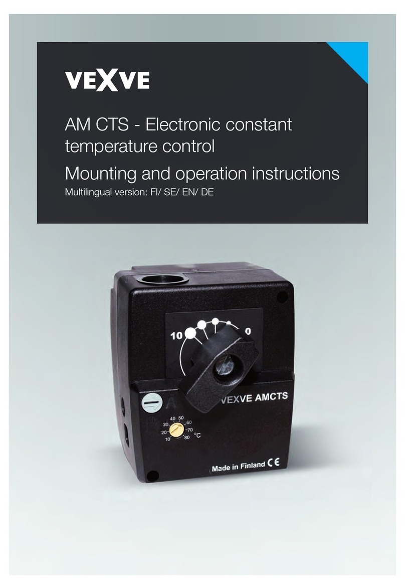
Vexve AUTOMIX 10 Service manual

AUTOMIX 10 (EN) 0508
AUTOMIX 10
MOUNTING AND OPERATING INSTRUCTIONS
GENERAL FUNCTIONS
AUTOMIX 10 is an advanced electronic temperature control for hydronic radiator and radiant floor
heating systems. It can easily be integrated into an existing heating system. The main supply and all
sensors have plug-in connections. The quick do-it-your-self installation saves on labor charges.
AUTOMIX 10 works continuously and proportionally. Through impulses from the sensors the controller
directs the motor to keep the valve plug in the position that corresponds to the actual heat requirement
of the house.
DELIVERY PARTS OF ART.NO 1210
1. Valve motor AUTOMIX 10 with built-in electronics and mounting kit
2. Adapter 230/18 VAC 200 mA with 1,7 m wire
3. Supply water sensor T1 with 1 m wire
4. Outdoor sensor T2 with 15 m wire
OPTIONALS
5. Room sensor AUTOMIX 10RB with 15 m wire, art.no 1211
AUTOMIX 10RB should be installed if the room temperature of the house fluctuates because the building is
affected by e.g. sunlight or wind. With AUTOMIX 10 RB the room temperature can be set between 12°C and
27°C.
6. Remote control AUTOMIX 10RC with 15 m wire, art.no 1212
Remote control AUTOMIX 10RC is designed for floor heating systems. The remote control provides a
convenient way to adjust the supply water temperature without going to the boiler room.
MOUNTING
Supply water sensor T1
Supply water sensor T1 is fastened to a non-insulated part of the supply pipe after the mixing valve.
For optimum temperature measuring the pipe and sensor have to be insulated afterwards.
Outdoor sensor T2
Outdoor sensor T2 is to be mounted on the north or northwestern outside wall at least 3 metres above
ground. The outdoor sensor must never be mounted above a window or near an air valve as this
would influence the sensor.
Room sensor AUTOMIX 10RB
Room sensor AUTOMIX 10RB is mounted at a place with an average temperature of the house. The room
sensor should not be placed where it can be affected by direct sunlight, heat radiation or draught. Radiators
with a thermostatic valve in the same room as the room sensor must be max. opened to obtain a correct
temperature control.
Remote control AUTOMIX 10RC
Remote control AUTOMIX 10RC is mounted at a convenient place for operating.

AUTOMIX 10 (EN) 0508
R
MAX
MIN
90
70
60
50
40
30
15
20
25
46
L
010
AUTOMIX 10
7
9
21
35
+10
10
5+5
0
O
C
O
C
A
B
C
D
E
F
G
H
VALVE MOTOR AUTOMIX 10
BCH E F
D
AG
1. Turn the spindle of valve A counter clockwise to the end position (open or closed). Remove the
knob/handle without changing the position of the spindle.
2. Screw the anti-rotation stop B into a convenient hole on the valve (if necessary remove an existing
screw).
3. Slide linkage C over the valve spindle. Place motor D onto linkage C until the anti-
rotation stop B engages into the slot of the motor.
4. On delivery the motor is in the anti-clockwise position. Turn scale E according to the open/closed
direction of the valve.
5. Place handle F onto the motor ensuring that the arrow points to the left end position of the scale.
Tighten the whole unit by means of screw G.
6. Using a screwdriver (No.3) turn the disengaging button H from ”A” to ”HAND” position and rotate the
valve with handle F from one end position to the other.
It is important that the motor can be moved from one end stop to the other (90°).
7. Turn disengaging button H back to ”A” which is the AUTOMATIC position.
FRONT PANEL OF MOTOR
A. Red LED – valve opens
B. Green LED – valve closes
C. Min. and Max. supply water temperature
D. Graph setting
E. Right or Left turning direction of motor
F. Parallel displacement of graph
G. Handle/Indicator of valve position
H. A = Automatic position, HAND = Manual position

AUTOMIX 10 (EN) 0508
18 V
T1
A
B
D
C
9
7
8
6
4
3
1
o
C
-30-20
2
0
+10 -10
5
o
90
C
20
30
40
50
60
70
80
T2
O
E
WIRING
AUTOMIX 10 is delivered with wires. The main supply and all sensors have plug-in connections.
The quick do-it-your-self installation minimizes installation problems.
Left side of motor
A. Adapter
B. Supply water sensor T1
Right side of motor
C. Outdoor sensor T2
D. Graphs
Motor under the cover
Connection E is placed under the motor cover.
Room sensor AUTOMIX 10RB and remote control
AUTOMIX 10RC are connected to E.
The cover has edge cuttings for the wire.

AUTOMIX 10 (EN) 0508
80
70
60
50
40
30
20
C
90
o
5
-10
+10 0
2
-20 -30 C
o
1
3
4
6
8
7
9
-40 -50
GRAPH SETTING
The regulating graph for a certain house is dependent on dimensions, location, insulation etc. Therefore it is
not possible to decide on a graph in advance. It has to be tried out.
The graph is set with knobs Dand F. The knobs work steplessly.
Initial setting
Regulating graph for radiator heating, set knob Don 5.
Regulating graph for floor heating, set knob Don 2.
Room temperature setting/parallel displacement
For parallel displacement / to obtain the desired room temperature use knob F. The supply water
temperature can be raised or lowered steplessly by 10°C from setting 0. A supply water temperature of
2,5ºC corresponds to 1ºC in room temperature.
Adjustments
Should the room temperature rise with falling outdoor temperature: lower knob D
raise knob F
Should the room temperature fall with falling outdoor temperature: raise knob D
lower knob F
Make only minor changes with knobs Dand F. When the house has an even room temperature despite
fluctuating outdoor temperatures, the correct regulating graph has been obtained.
N.B! Heat affects slowly. When a temperature setting has been changed it takes several hours before the
room temperature corresponds to the new setting due to dimensions of the heating system and the insulation
of the house. A floor heating system responds even slower to a new setting than a radiator system.
REGULATING GRAPHS
Supply water temperature
Outdoor temperature
RIGHT OR LEFT TURNING DIRECTION OF MOTOR
Right or Left turning direction of the motor is selected with knob E. At delivery the motor opens the
mixing valve clockwise. Knob E is at R = RIGHT.
If the mixing valve opens counter clockwise the knob E is to be movde to L = LEFT.

AUTOMIX 10 (EN) 0508
SETTING MIN. AND MAX. SUPPLY WATER TEMPERATURE
Min. supply water temperature can be set between 15°C – 35°C and max. supply water temperature
between 40°C – 90°C. When min. supply water temperature is set to 30°C or below, the max.
supply water temperature will automatically be 40°C. When min. supply water temperature is set above
30°C, the max. supply water temperature is automatically 45°C.
Setting of min. supply water temperature is used in radiant floor
heating applications to obtain a comfortable floor temperature.
Min. supply water temperature is selected with knob C.
In the example graph 3 has been selected and the min. supply water
temperature is set to 22°C. Max. supply water temperature will
automatically be 40°C.
Setting of max. supply water temperature is used in hydronic
radiator heating systems.
Max. supply water temperature is selected with knob C.
In the example graph 6 has been selected. Max.supply water
temperature is set to 45°C.
SENSOR RESISTANCE
Sensor resistance is measured at the two middle wires of the 4-wire cable contact.
Supply water sensor T1 Outdoor sensor T2
0 820
10 889
20 962
30 1039
40 1118
50 1202
60 1288
70 1379
80 1472
90 1569
100 1670
°C
20 2,67
15 3,28
10 4,06
5 5,04
0 6,31
-5 7,93
-10 10,05
-15 12,84
-20 16,54
-25 21,40
-30 27,93
°C k

AUTOMIX 10 (EN) 0508
OPTIONALS
AUTOMIX 10RB is a room sensor for measuring and setting the
temperature inside the house.
AUTOMIX 10RB should be installed if the room temperature
fluctuates because the building is affected by sunlight or wind.
A green LED indicates that power is on. When the motor runs, the
LED dims slightly.
AUTOMIX 10RC is a remote control designed for floor heating
systems. It is used to conveniently adjust/parallel displace the
heating graph. Supply water temperaure can be lowered 9°C
or raised 6°C. AUTOMIX 10RC corresponds to the function
parallel displacement F.
A green LED indicates that power is on. When the motor runs, the
LED dims slightly.
TECHNICAL DATA
Type of control PI-control with microprocessor
Voltage 18 VAC 50/60 Hz
Adapter 230/18 VAC 200 mA with 1,7 m wire
Power consumption 3 VA
Torque 5 Nm
Angle of rotation 90°
Heating graphs 1 to 9, stepless
Parallel displacement +/- 10°C supply water temperature, stepless
Min. supply water limiter +15°C to +35°C supply water temperature
Max.supply water limiter +40°C to +90°C supply water temperature
Room sensor AM 10RB +12°C to +27°C room temperature, stepless
Remote control AM 10RC -9°C to +6°C supply water temperature, stepless
Manual operation Yes, in case of power failure
Prtotection class IP 40
Dimensions 77 x 90 x 90 mm
Weight 0,53 kg
www.acaso.se
This manual suits for next models
1
Table of contents
Other Vexve Temperature Controllers manuals
Popular Temperature Controllers manuals by other brands

iQe
iQe CP027 installation instructions

HANYOUNG NUX
HANYOUNG NUX HD6 instruction manual

Ketotek
Ketotek KT4000 operating manual

Autonics
Autonics KPN Series User Manual for Communication

Carrier
Carrier SYSTXCCITN01-A Infinity owner's manual

Ever Cool
Ever Cool TC140 Operating & maintenance instruction manual

System Sensor
System Sensor 2351TB Installation and maintenance instructions

J-KEM Scientific
J-KEM Scientific Gemini user manual

gefran
gefran 650 Series Abbreviated Manual

Tech Controllers
Tech Controllers EU-M-9t user manual

M-system
M-system R3-TC2 instruction manual

Super Systems
Super Systems 9130 Series Operation manual