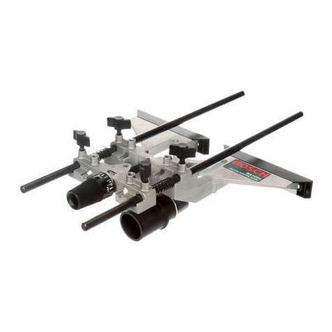
Victaulic VE226 Power Drive Kit User manual

R
VE226 Power Drive Kit
Kit for connectiing a
VE226 Roll Grooving Tool
to a Ridgid* 700 Power Drive
Installation Instructions
• Read all instructions and warnings before installing this kit or operating any tools.
• Wear safety glasses, hardhat, foot protection and hearing protection.
• Save these instructions for future reference.
If you need additional copies of any literature, or if you have questions about the safe operation of this tool, contact Victaulic Tool Company,
*Ridgid is a registered trademark of the Ridge Tool Company

1
HAZARD IDENTIFICATION
Definitions for identifying the various hazard levels are provided below.
This safety alert symbol indicates important safety messages. When you see this symbol, be alert to the possibil-
ity of personal injury. Carefully read and fully understand the message that follows.
The use of the word “DANGER” identifies an immediate hazard with a likelihood of
death or serious personal injury if instructions, including recommended precautions,
are not followed.
The use of the word “WARNING” identifies the presence of hazards or unsafe practices
that could result in death or serious personal injury if instructions, including
recommended precautions, are not followed.
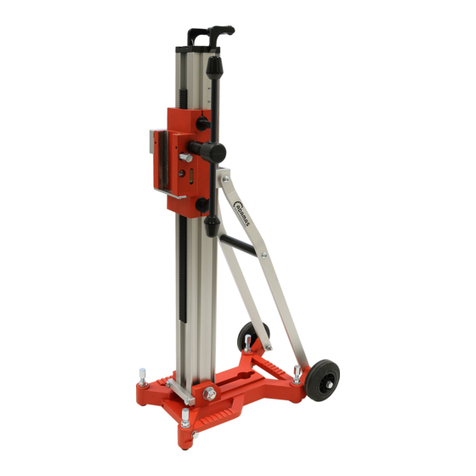
CONTENTS OF KIT
Item No. Description Qty.
1 Power Drive/Tool Stand 1
2 Foot Switch for Power Drive 1
3 Adapter Plate 1
4 Pins 2
5 Bolts with Flat Washers and Wing Nuts 4
6 Power Drive Trigger Lock 1
7 Power Drive Adapter 1
IMPORTANT INFORMATION
These instructions are a supplement to highlight the necessary steps that must be performed to adapt a VE226 Roll
Grooving Tool for use with a Ridgid 700 Power Drive. Refer to the VE226 Operating Instructions (supplied with this kit) and
the Ridgid 700 Operator’s Manual for complete safety information, tool setup, grooving, troubleshooting, maintenance
information, etc.
1. Select location for tool. The choice of tool location and position should take into account the following factors:
a.) Pipe handling support requirements
b.) Power supply requirements
c.) Pipe support and tool anchoring requirements
2. Place the power drive/tool stand on level ground. Secure the stand to a platform or the floor.
1
2
3
456
7
® Registered Trademark of Victaulic © Copyright 2001 Victaulic Printed in U S A
2
KIT INSTALLATION
1.
Install adapter plate onto power drive/tool stand, as
shown above.
2.
Install bolts with flat washers through the four locations
on the adapter plate and into the power drive/tool stand.
3.
Install wing nuts onto four bolts, as shown above, and
tighten.
4.
Install VE226 tool onto arms of power drive/tool stand.
5.
Install a pin into each hole in the arms of the power
drive/tool stand, as shown above. Close the pins.
• To prevent electric shock, make sure the power drive/
foot switch is unplugged from the electrical source before
attempting to remove or install any components.
• DO NOT plug power drive/foot switch into power source until
instructed.
Failure to follow these instructions could result in death or
serious personal injury.
• DO NOT operate power drive without a safety foot switch. A foot switch is required
to operate the tool safely.
Failure to follow this instruction could result in serious personal injury.

3
6.
Remove existing drive adapter or threading die from
power drive.
7.
Locate the drive tangs on the Ridgid 700 Power Drive.
8.
Locate the recesses in the power drive adapter.
9.
Locate the tapped hole in the body of the power drive.
10.
Install power drive adapter into power drive by aligning
the drive tangs (shown in Step 7) with the recesses in the
adapter (show in Step 8). Make sure the shaft of the
adapter (shown in Step 8) faces the same side of the power
drive as the tapped hole (shown in Step 9).
10a.
Make sure the power drive adapter engages
completely into the power drive, as shown above.
Power Drive
Adapter Shaft

4
11.
Install power drive onto VE226 tool with the set screws
of the power drive adapter shaft aligned with the flats on
the tool drive shaft, as shown above. If necessary, rotate the
VE226 tool drive shaft by hand for proper alignment.
12.
Align tapped hole in power drive body with the hole in
the adapter plate, as shown above.
13.
Loosely install bolt (attached to adapter plate) through
adapter plate’s hole and into tapped hole in power drive
body, as shown above.
14.
Before tightening the three set screws, double-check
that the flats on the VE226 tool drive shaft are aligned with
the set screws of the power drive adapter shaft. Tighten
the three set screws on the power drive adapter shaft with
the hex key wrench included with theVE226 tool.
15.
Tighten bolt that you installed in step 13.
• Make sure the power drive/foot switch is unplugged before installing the power drive
trigger lock.
Failure to follow these instructions could result in serious personal injury.

5
16. Install power drive trigger lock onto power drive.
Tighten two thumbscrews on underside of trigger lock.
16a
. It is important that the trigger lock’s tab pushes down
on the topside trigger to produce correct rotation of
grooving rolls.
17.
Plug power drive into footswitch, as shown above.
Plug foot switch cord into a grounded electrical outlet,
according to requirements in the VE226 Operating
Instructions and the Ridgid 700 Operator’s Manual.
18.
Follow rest of steps in the VE226 Operating
Instructions, starting with section B, "Tubing/Pipe
Preparation" on page 6.
• DO NOT operate power drive without a safety foot switch. A foot switch is required
to operate the tool safely.
Failure to follow this instruction could result in serious personal injury.
Trigger Lock Tab
Th mb Screws Bolt

6
TM-VE226.Kit
3119 RevA 3/01
Table of contents