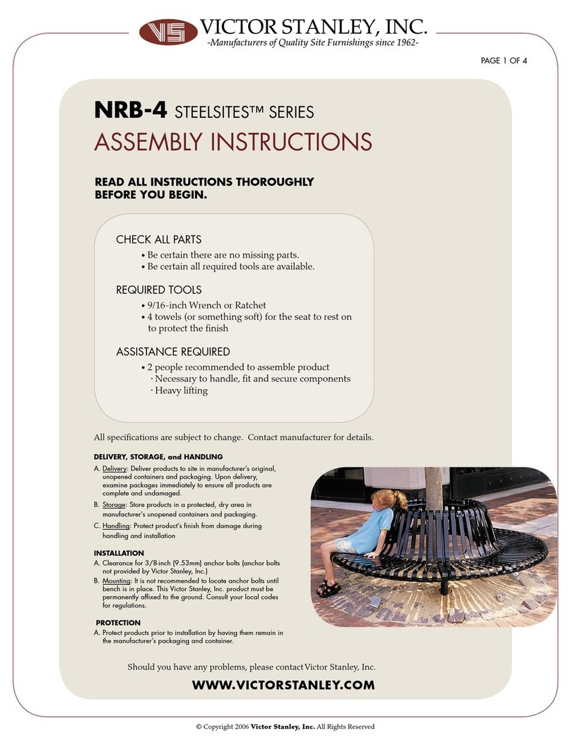
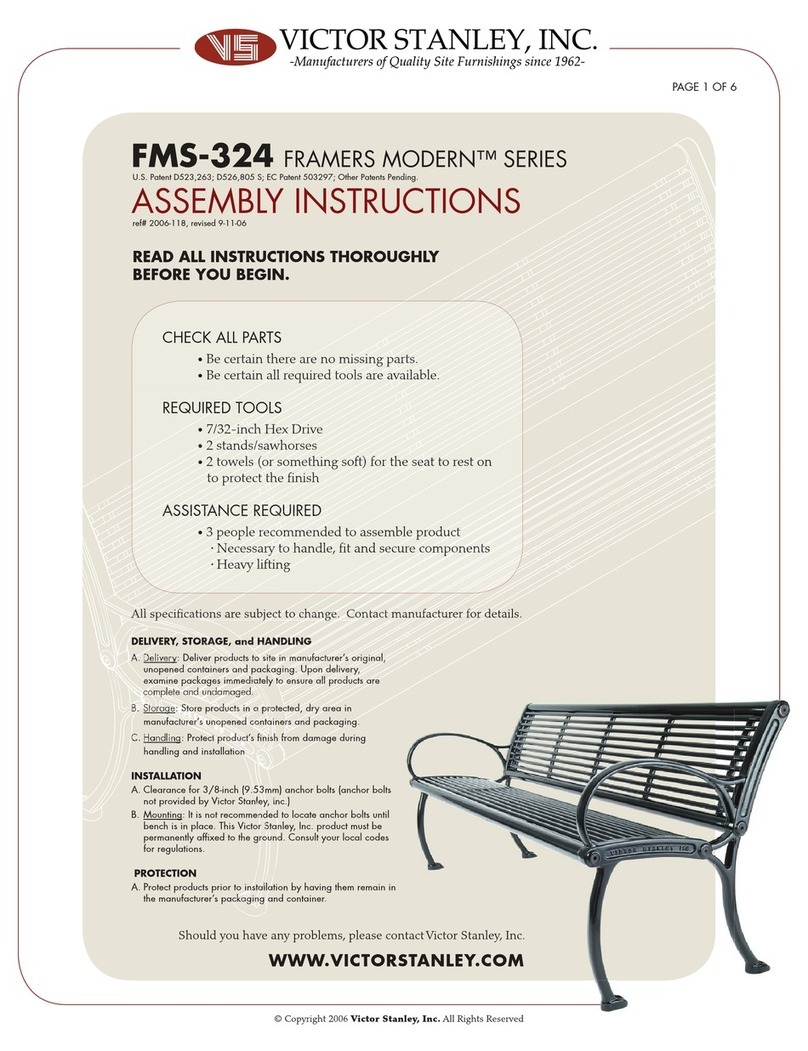
VICTOR STANLEY GreenSite Series User manual

CM-324 GREENSITE SERIES™
CHECK ALL PARTS
•Be certain there are no missing parts.
•Be certain all required tools are available.
REQUIRED TOOLS
•5/32 and 7/32-inch Hex Drive
•2 stands/sawhorses
• 2 towels (or something so) for the seat to rest on
to protect the nish
•1/4-inch Allen Wrench
ASSISTANCE REQUIRED
•3 people recommended to assemble product
• Necessary to handle, t and secure components
• Heavy liing
WWW.VICTORSTANLEY.COM
Should you have any problems, please contact Victor Stanley, Inc.
READ ALL INSTRUCTIONS THOROUGHLY
BEFORE YOU BEGIN.
© Copyright 2009 Victor Stanley, Inc. All Rights Reserved
DELIVERY, STORAGE, and HANDLING
A. Delivery: Deliver products to site in manufacturer’s original,
unopened containers and packaging. Upon delivery,
examine packages immediately to ensure all products are
complete and undamaged.
B. Storage: Store products in a protected, dry area in
manufacturer’s unopened containers and packaging.
C. Handling: Protect product’s nish from damage during
handling and installation
INSTALLATION
A. Clearance for 3/8-inch (9.53mm) anchor bolts (anchor bolts
not provided by Victor Stanley, Inc.)
B. Mounting: It is not recommended to locate anchor bolts until
bench is in place. This Victor Stanley, Inc. product must be
permanently afxed to the ground. Consult your local codes
for regulations.
PROTECTION
A. Protect products prior to installation by having them remain in
the manufacturer’s packaging and container.
All specications are subject to change. Contact manufacturer for details.
PAGE 1 OF 9
ref# 2009-130, revised 4-22-09
U.S. Patent D523,263 S; D526,805 S; D563,689 S; EC Reg. No. 000503297-0001; Canadian Patents 110953; 110954.
ASSEMBLY INSTRUCTIONS
FM-324 FRAMERS MODERN™ SERIES

WWW.VICTORSTANLEY.COM
Should you have any problems, please contact Victor Stanley, Inc.
PARTS LIST
COMPONENTS HARDWARE
3/8-inch x 3/4-inch SS
BUTTON HEAD CAP SCREW 3/8-inch LOCK WASHER 3/8-inch SS FLAT WASHER
EXAMPLE
CONFIGURED FOR USE
LEFT CAST LEG FRAME RIGHT CAST LEG FRAME
AB C
G H
x16 x16 x16
x1 x1
PAGE 2 OF 9
© Copyright 2009 Victor Stanley, Inc. All Rights Reserved
CM-324 GREENSITE SERIES™
FM-324 FRAMERS MODERN™ SERIES
ASSEMBLY INSTRUCTIONS
TOOLS REQUIRED
2 SAWHORSES
2 TOWELS
(or something soft to protect nish)
HANDS
*This symbolizes when to
use HAND to tighten.
5/32-inch and
7/32-inch HEX DRIVE
*This symbolizes when to
use TOOL to tighten.
BENCH SLATS
K
x12
*This symbolizes when to
use WRENCH for alignment.
DE
x60 for 12-foot model
Flat Head HEX DRIVE LAG SCREW 3/4-inch FLAT WASHER 5/32-inch HEX DRIVE BIT
F
x1
x72 for 16-foot model
x60 for 12-foot model
x72 for 16-foot model
BENCH SECTION
I
x1
J
x4
CENTER CAST LEG FRAME

WWW.VICTORSTANLEY.COM
STEP #1
CM-324 GREENSITE SERIES™
FM-324 FRAMERS MODERN™ SERIES
ASSEMBLY INSTRUCTIONS
PAGE 3 OF 9
© Copyright 2009 Victor Stanley, Inc. All Rights Reserved
#2
Set one bench section face down on sawhorse
using towels to protect nish.
Aach leg frames using (3) bolts / washers (parts A, B & C togeth-
er). Tighten by hand. Leave leg frame on one side angled out. If
necessary, use a 1/4-inch Allen Wrench as a guide for aligning nuts
and bolts as shown below in gure A.
HAND TIGHTEN
1
2
3
PLACE TOWELS BETWEEN
BENCH AND SAWHORSE
TO PROTECT FINISH
1 2 3
Should you have any problems, please contact Victor Stanley, Inc.
Figure A
EXAMPLE CONFIGURED
FOR USE

WWW.VICTORSTANLEY.COM
STEP #3
CM-324 GREENSITE SERIES™
FM-324 FRAMERS MODERN™ SERIES
ASSEMBLY INSTRUCTIONS
PAGE 4 OF 9
© Copyright 2009 Victor Stanley,Inc. All Rights Reserved
#4
Aach second bench section to be used as a backrest.
Aach leg frames using (5) bolts (same bolt/washer combination
used in Step 2.). Again, using the Allen Wrench as a guide for
alignment, tighten bolts by hand.
1
2
3
4
5
HAND TIGHTEN
Should you have any problems, please contact Victor Stanley, Inc.

WWW.VICTORSTANLEY.COM
STEP #5
CM-324 GREENSITE SERIES™
FM-324 FRAMERS MODERN™ SERIES
ASSEMBLY INSTRUCTIONS
PAGE 5 OF 9
© Copyright 2009 Victor Stanley, Inc. All Rights Reserved
#6
Push leg frames in towards bench section.
Tighten all bolts now with tool.
Tighten only until lock washer is at as shown below on right.
DO NOT OVER TIGHTEN.
#6
TOOL TIGHTEN
Lock washer when HAND tightened. Lock washer when TOOL tightened.
DO NOT OVER TIGHTEN.
Should you have any problems, please contact Victor Stanley, Inc.

WWW.VICTORSTANLEY.COM
CM-324 GREENSITE SERIES™
FM-324 FRAMERS MODERN™ SERIES
ASSEMBLY INSTRUCTIONS
PAGE 6 OF 9
© Copyright 2007 Victor Stanley, Inc. All Rights Reserved
Should you have any problems, please contact Victor Stanley, Inc.
STEP #7
#8
Once the rst (2) seat sections are ached, carefully li the bench
and lower it to the ground using (3) people. Once bench is reposi-
tioned, have one person slide the 3rd seating section into place as
shown below. Once it is in place, align the bolt holes and aach
using the same bolt combination used in Step 2.
Aach the front of the 3rd leg casting using the same hardware as
used in Step 7. Be sure to leave the back end angled out as shown
below to allow room for the backrest to t in place.
HAND TIGHTEN
EXAMPLE CONFIGURED
FOR USE
2
1
HAND TIGHTEN
ALIGNMENT

Lock washer when HAND tightened. Lock washer when TOOL tightened.
WWW.VICTORSTANLEY.COM
CM-324 GREENSITE SERIES™
FM-324 FRAMERS MODERN™ SERIES
ASSEMBLY INSTRUCTIONS
PAGE 7 OF 9
© Copyright 2007 Victor Stanley, Inc. All Rights Reserved
Should you have any problems, please contact Victor Stanley, Inc.
STEP #9
#10
Next, aach the 4th seating section to be used as the second back-
rest. Use the same hardware as used in Steps 7 & 8. Align the bolt
holes (as done in Step 2) by using the 1/4-inch Allen Wrench. Hand
tighten only.
HAND TIGHTEN
Once the entire frame of the bench has been assembled, tighten all
bolts with tool. Tighten only until lock washer is at.
DO NOT OVER TIGHTEN.
TOOL TIGHTEN
EXAMPLE CONFIGURED
FOR USE

WWW.VICTORSTANLEY.COM
CM-324 GREENSITE SERIES™
FM-324 FRAMERS MODERN™ SERIES
ASSEMBLY INSTRUCTIONS
PAGE 8 OF 9
© Copyright 2009 Victor Stanley, Inc. All Rights Reserved
Should you have any problems, please contact Victor Stanley, Inc.
STEP #11
#12
Next, install all bench slats using the supplied hardware. Make sure
the pre-drilled pilot holes are facing down and insert lag screw from
rear (As shown in Figure B). Hand tighten only.
Once the slats are aached and aligned properly, tighten the front
and back slats in an alternating sequence. (Front Right, Back Le,
etc.) Tighten all screws with tool.
DO NOT OVER TIGHTEN.
HAND TIGHTEN
TOOL TIGHTEN
For this step
use lag screw
combination
(parts D & E)
as shown:
Use provided
tool for step 11
Figure B

WWW.VICTORSTANLEY.COM
CM-324 GREENSITE SERIES™
FM-324 FRAMERS MODERN™ SERIES
ASSEMBLY INSTRUCTIONS
PAGE 9 OF 9
© Copyright 2009 Victor Stanley, Inc. All Rights Reserved
CM-324 GREENSITE SERIES™
FM-324 FRAMERS MODERN™ SERIES
FINAL PRODUCT
Thank you for choosing Victor Stanley, Inc.
Should you have any problems, please contact Victor Stanley, Inc.
This manual suits for next models
3
Table of contents
Other VICTOR STANLEY Outdoor Furnishing manuals
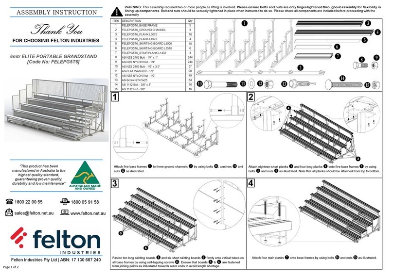
Popular Outdoor Furnishing manuals by other brands
Home Styles
Home Styles 88 5562 34 Assembly instructions

SUNVILLA
SUNVILLA 1476134 Assembly / care & use instructions

L.L.Bean
L.L.Bean ADIRONDACK GLIDER Assembly instructions

Forest garden
Forest garden MTGSH86 manual

Leisure made
Leisure made MARIETTA 906420 Assembly instructions

Pergola Depot
Pergola Depot Big Kahuna Pergola Kit Assembly instructions