Victron energy Color Control GX User manual

Table of Contents
1. Safety instructions ................................................................................................................... 1
2. Introduction ........................................................................................................................... 2
2.1. What is the Color Control GX? ............................................................................................. 2
2.2. What's in the box? ........................................................................................................... 2
3. Installation ............................................................................................................................. 3
3.1. Color Control GX Overview of connections .............................................................................. 3
3.2. Mounting options and accessories ........................................................................................ 4
3.3. Powering the Color Control GX ............................................................................................ 5
3.3.1. Snap-on ferrite beads for class B EMI compliance ............................................................ 5
3.4. Relay connections ........................................................................................................... 7
4. Connecting Victron products ...................................................................................................... 8
4.1. VE.Bus Multis/Quattros/Inverters .......................................................................................... 8
4.2. AC load monitoring .......................................................................................................... 9
4.3. Battery Monitor SmartShunt, BMV-700 series; and MPPTs with a VE.Direct port ................................... 9
4.3.1. DC load monitor mode .......................................................................................... 10
4.4. VE.Can Devices ........................................................................................................... 11
4.5. VE.Can Interfaces ......................................................................................................... 11
4.6. Inverter RS, Multi RS and MPPT RS .................................................................................... 11
4.7. BMV-600 series ............................................................................................................ 11
4.8. DC Link Box ................................................................................................................ 12
4.9. VE.Can Resistive Tank Sender Adapter ................................................................................ 12
4.10. Connecting a GX Tank 140 ............................................................................................. 12
5. Connecting supported non-Victron products ................................................................................. 13
5.1. Connecting a PV Inverter ................................................................................................. 13
5.2. Connecting a USB GPS .................................................................................................. 13
5.3. Connecting a NMEA 2000 GPS ......................................................................................... 14
5.4. Connecting a Fischer Panda Generator ................................................................................ 14
5.5. Connecting third-party NMEA 2000 tank senders ..................................................................... 14
5.6. Mopeka Pro Check LPG and Water Bluetooth Sensors .............................................................. 16
5.6.1. Installation ........................................................................................................ 16
5.6.2. Configuration .................................................................................................... 17
5.6.3. Tank level monitoring ........................................................................................... 18
5.7. Wakespeed WS500 alternator regulator support ...................................................................... 19
5.7.1. Introduction ...................................................................................................... 19
5.7.2. Requirements .................................................................................................... 19
5.7.3. Wiring the WS500 to VE.Can .................................................................................. 19
5.7.4. Wiring Example .................................................................................................. 20
5.7.5. GX device user interface for WS500 .......................................................................... 21
5.7.6. WS500 data on the VRM Portal ............................................................................... 21
5.7.7. Troubleshooting & FAQ ......................................................................................... 22
5.8. Wireless Bluetooth Ruuvi temperature sensors ........................................................................ 23
5.9. Connecting IMT Solar Irradiance, Temperature and Wind Speed Sensors ......................................... 25
5.9.1. Data Visualisation - VRM ....................................................................................... 28
6. Internet connectivity ............................................................................................................... 29
6.1. Ethernet LAN port ......................................................................................................... 29
6.2. WiFi ......................................................................................................................... 30
6.3. GX LTE 4G ................................................................................................................. 30
6.4. Mobile (cellular) network using a 3G or 4G router ..................................................................... 30
6.5. USB tethering using a mobile phone .................................................................................... 31
6.6. Manual IP configuration ................................................................................................... 31
6.7. Connecting both Ethernet and WiFi (failover) .......................................................................... 31
6.8. Minimise internet traffic ................................................................................................... 31
6.9. More information about setting up an internet connection and VRM ................................................ 32
7. Accessing the GX device ......................................................................................................... 33
7.1. Accessing the Remote Console via local LAN/WiFi Network ........................................................ 34
Color Control GX Manual

7.1.1. Alternative methods to find the IP address for Remote Console .......................................... 34
7.2. Accessing via VRM ........................................................................................................ 35
7.3. The Remote Console menu .............................................................................................. 36
8. Configuration ....................................................................................................................... 37
8.1. Menu structure and configurable parameters .......................................................................... 37
8.2. Battery state of charge (SoC) ............................................................................................ 44
8.2.1. Which device should I use for SoC calculation? ............................................................. 44
8.2.2. The different solutions explained in detail .................................................................... 44
8.2.3. Notes on SoC .................................................................................................... 45
8.2.4. Selecting SoC source ........................................................................................... 45
8.2.5. Details on VE.Bus SOC ........................................................................................ 46
8.2.6. The System Status menu ...................................................................................... 46
8.3. Customise the logo on the Boat & Motorhome page .................................................................. 47
8.4. Temperature relay configuration ......................................................................................... 48
9. Firmware updates .................................................................................................................. 50
9.1. Changelog .................................................................................................................. 50
9.2. Updating from version 1.x to 2 ........................................................................................... 50
9.3. Via internet or with microSD-card/USB-stick ........................................................................... 50
9.3.1. Direct download from the internet ............................................................................. 50
9.3.2. MicroSD-card or USB-stick .................................................................................... 51
9.4. Revert to a previous firmware version .................................................................................. 51
9.4.1. Stored firmware backup feature ............................................................................... 52
9.4.2. Install a specific firmware version from SD/USB ............................................................ 53
10. VE.Bus Inverter/charger monitoring .......................................................................................... 54
10.1. Input current-limiter setting .............................................................................................. 54
10.2. Phase rotation warning .................................................................................................. 55
10.3. Grid failure monitoring ................................................................................................... 56
10.4. Advanced menu .......................................................................................................... 56
10.5. Alarm status monitoring ................................................................................................. 57
10.6. VE.Bus alarm setup menu .............................................................................................. 57
10.7. Device menu .............................................................................................................. 57
11. DVCC - Distributed Voltage and Current Control ........................................................................... 58
11.1. Introduction and features ................................................................................................ 58
11.2. DVCC Requirements .................................................................................................... 59
11.3. DVCC effects on the charge algorithm ................................................................................ 60
11.3.1. DVCC effects when there is more than one Multi/Quattro connected ................................... 60
11.4. DVCC features for all systems .......................................................................................... 61
11.4.1. Limit charge current ........................................................................................... 61
11.4.2. Limit managed battery charge voltage ...................................................................... 61
11.4.3. Shared Voltage Sense (SVS) ................................................................................. 62
11.4.4. Shared Temperature Sense (STS) ........................................................................... 62
11.4.5. Shared Current Sense (SCS) ................................................................................. 63
11.4.6. Controlling BMS ................................................................................................ 63
11.5. DVCC features when using CAN-bus BMS battery .................................................................. 64
11.6. DVCC for systems with the ESS Assistant ............................................................................ 65
12. VRM Portal ......................................................................................................................... 66
12.1. VRM Portal introduction ................................................................................................. 66
12.2. Registering on VRM ..................................................................................................... 66
12.3. Datalogging to VRM ..................................................................................................... 66
12.4. Troubleshooting data logging ........................................................................................... 68
12.5. Analysing data offline, without VRM ................................................................................... 70
12.6. Remote Console on VRM - Setup ...................................................................................... 71
12.7. Remote Console on VRM - Troubleshooting ......................................................................... 71
13. Marine MFD integration by App ................................................................................................ 73
13.1. Introduction & requirements ............................................................................................ 73
13.2. Compatible MFDs and instructions .................................................................................... 74
13.3. Raymarine MFD Integration ............................................................................................ 74
13.3.1. Introduction ..................................................................................................... 74
Color Control GX Manual

13.3.2. Compatibility .................................................................................................... 74
13.3.3. Wiring ........................................................................................................... 74
13.3.4. GX device configuration ....................................................................................... 75
13.3.5. Configuring multiple battery measurements ................................................................ 75
13.3.6. Installation step-by-step ....................................................................................... 75
13.3.7. NMEA 2000 .................................................................................................... 76
13.3.8. Generic and supported PGNs ................................................................................ 76
13.3.9. Instancing requirements when using Raymarine ........................................................... 76
13.3.10. Before LightHouse 4.1.75 ................................................................................... 76
13.3.11. LightHouse 4.1.75 and newer ............................................................................... 77
13.4. Navico MFD Integration ................................................................................................. 77
13.4.1. Introduction ..................................................................................................... 77
13.4.2. Compatibility .................................................................................................... 77
13.4.3. Wiring ........................................................................................................... 78
13.4.4. GX device configuration ....................................................................................... 78
13.4.5. Configuring multiple battery measurements ................................................................ 78
13.4.6. Installation step-by-step ....................................................................................... 79
13.4.7. NMEA 2000 .................................................................................................... 79
13.4.8. Generic and supported PGNs ................................................................................ 79
13.4.9. Troubleshooting ................................................................................................ 80
13.5. Garmin MFD Integration ................................................................................................ 80
13.5.1. Introduction ..................................................................................................... 80
13.5.2. Compatibility .................................................................................................... 80
13.5.3. Wiring ........................................................................................................... 80
13.5.4. GX device configuration ....................................................................................... 81
13.5.5. Configuring multiple battery measurements ................................................................ 81
13.5.6. Installation step-by-step ....................................................................................... 82
13.5.7. NMEA 2000 .................................................................................................... 82
13.5.8. Generic and supported PGNs ................................................................................ 82
13.6. Furuno MFD Integration ................................................................................................. 83
13.6.1. Introduction ..................................................................................................... 83
13.6.2. Compatibility .................................................................................................... 83
13.6.3. Wiring ........................................................................................................... 83
13.6.4. Configuration ................................................................................................... 83
13.6.5. Configuring multiple battery measurements ................................................................ 84
13.6.6. NMEA 2000 .................................................................................................... 84
13.6.7. Generic and supported PGNs ................................................................................ 85
14. Marine MFD integration by NMEA 2000 ....................................................................................... 86
14.1. NMEA 2000 Introduction ................................................................................................ 86
14.2. Supported Devices / PGNs ............................................................................................. 86
14.3. NMEA 2000 Configuration .............................................................................................. 88
14.4. Configuration of multiple tank level measurements via NMEA2000-out for Raymarine MFDs ................. 88
14.5. Configuration of multiple tank level measurements via NMEA2000-out for Garmin MFDs ...................... 89
14.6. Configuration of multiple tank level measurements via NMEA2000-out for Navico MFDs ...................... 90
14.7. Configuration of multiple tank level measurements via NMEA2000-out for Furuno MFDs ...................... 92
14.8. NMEA 2000 Configuring Device Instances ........................................................................... 92
14.9. NMEA2000-out technical details ....................................................................................... 93
14.9.1. NMEA 2000 Glossary ......................................................................................... 93
14.9.2. NMEA 2000 Virtual-devices .................................................................................. 93
14.9.3. NMEA 2000 Classes and Functions ......................................................................... 93
14.9.4. NMEA 2000 Instances ........................................................................................ 94
14.9.5. NMEA 2000 Changing Instances ............................................................................ 95
14.9.6. PGN 60928 NAME Unique Identity Numbers .............................................................. 95
15. RV-C Support ...................................................................................................................... 96
15.1. RV-C Introduction ........................................................................................................ 96
15.2. Limitations ................................................................................................................ 96
15.3. Supported Devices ....................................................................................................... 96
15.4. RV-C Configuration ...................................................................................................... 97
15.4.1. Configuration of RV-C out devices ........................................................................... 98
15.5. Garnet SeeLevel II 709-RVC & Victron GX device support ......................................................... 99
15.5.1. Wiring the Garnet SeeLevel II 709-RVC tank level sensor to a GX device ............................. 99
15.5.2. Installation and configuration ................................................................................. 99
16. GX - Generator auto start/stop ................................................................................................ 100
16.1. Generator auto start/stop introduction ................................................................................ 100
Color Control GX Manual

16.2. Wiring ..................................................................................................................... 100
16.3. Enabling the start/stop function ....................................................................................... 100
16.4. General start/stop menu ............................................................................................... 101
16.5. Settings menu ........................................................................................................... 101
16.6. Conditions: User definable parameters that trigger an automatic generator start/stop ......................... 102
16.6.1. Generator stop when AC-input becomes available after a mains failure ............................... 102
16.6.2. Relays triggered by Battery SoC ............................................................................ 102
16.6.3. Relays triggered by Battery Current ........................................................................ 103
16.6.4. Relays triggered by Battery Voltage ........................................................................ 103
16.6.5. Relays triggered by AC load ................................................................................. 103
16.6.6. Relays triggered by Inverter High temperature ............................................................ 104
16.6.7. Relays triggered by Inverter overload ...................................................................... 104
16.6.8. Automatic periodic 'Test run' ................................................................................. 104
16.6.9. Manual Start Feature ......................................................................................... 104
16.6.10. Quiet hours ................................................................................................... 105
16.7. Troubleshooting ......................................................................................................... 106
17. Reset to factory defaults procedure ......................................................................................... 107
18. Troubleshooting ................................................................................................................. 108
18.1. Error Codes .............................................................................................................. 108
18.2. FAQ ....................................................................................................................... 109
18.2.1. Q1: I cannot switch my Multi/Quattro system on or off ................................................... 109
18.2.2. Q2: Do I need a BMV to see proper battery state of charge? ........................................... 109
18.2.3. Q3: I have no internet, where can I insert a SIM card? ................................................... 109
18.2.4. Q4: Can I connect both a GX Device and a VGR2/VER to a Multi/Inverter/Quattro? ................. 109
18.2.5. Q5: Can I connect multiple Color Control GX to a Multi/Inverter/Quattro? ............................. 109
18.2.6. Q6: I see incorrect current (amps) or power readings on my CCGX ................................... 110
18.2.7. Q7: There is a menu entry named "Multi" instead of the VE.Bus product name ...................... 110
18.2.8. Q8: There is a menu entry named "Multi", while there is no Inverter, Multi or Quattro connected .. 110
18.2.9. Q9: When I type the IP address of the Color Control GX into my browser, I see a web page
mentioning Hiawatha? ................................................................................................ 111
18.2.10. Q10: I have multiple Solar chargers MPPT 150/70 running in parallel. From which one will I
see the relay status in the CCGX menu? ........................................................................... 111
18.2.11. Q11: How long should an automatic update take? ...................................................... 111
18.2.12. Q12: I have a VGR with IO Extender, how can I replace this with a Color Control GX? ............ 111
18.2.13. Q13: Can I use Remote VEConfigure, as I was doing with the VGR2? ............................... 111
18.2.14. Q14: The Blue Power Panel could be powered through the VE.Net network, can I also do that
with a Color Control GX? ............................................................................................. 111
18.2.15. Q15: What type of networking is used by the Color Control GX (TCP and UDP ports)? ........... 111
18.2.16. Q16: What is the functionality behind the menu item Remote support (SSH) in the Ethernet
menu? ................................................................................................................... 112
18.2.17. Q17: I don’t see support for VE.Net products in the list, is that still coming? ......................... 112
18.2.18. Q18: What is the data usage of the Color Control GX? ................................................. 112
18.2.19. Q19: How many AC Current Sensors can I connect in one VE.Bus system? ........................ 112
18.2.20. Q20: Issues with Multi not starting when CCGX is connected / Caution when powering the
CCGX from the AC-out terminal of a VE.Bus Inverter, Multi or Quattro ......................................... 112
18.2.21. Q21: I love Linux, programming, Victron and the CCGX. Can I do more? ........................... 113
18.2.22. Q22: How do I change the logo ............................................................................ 113
18.2.23. Q23: Multi restarts all the time (after every 10sec) ...................................................... 113
18.2.24. Q24: What is Error #42? .................................................................................... 113
18.2.25. Q25: My GX device reboots itself. What is causing this behavior? .................................... 113
18.2.26. GPL Note .................................................................................................... 114
19. Technical specifications ........................................................................................................ 115
19.1. Technical specifications ................................................................................................ 115
20. Appendix .......................................................................................................................... 116
20.1. RV-C ...................................................................................................................... 116
20.1.1. Supported DGNs .............................................................................................. 116
20.1.2. RV-C out ....................................................................................................... 116
20.1.3. DGN 60928 Unique Identity Numbers ...................................................................... 122
20.1.4. RV-C in ......................................................................................................... 122
20.1.5. Device Classes ............................................................................................... 122
20.1.6. Instance Translation .......................................................................................... 123
20.1.7. RV-C Fault and Error Handling .............................................................................. 123
Color Control GX Manual
1. Safety instructions
SAVE THESE INSTRUCTIONS – This manual contains important instructions that shall be followed
during installation, setup, operation and maintenance.
• Please read this manual carefully before the product is installed and put into use
• Make sure you have the latest version of the manual. The most recent version can be downloaded from the product page.
• Install the product in a heatproof environment. Ensure therefore that there are no chemicals, plastic parts, curtains or other
textiles, etc. in the immediate vicinity of the equipment.
• Ensure that the equipment is used under the correct operating conditions. Never operate it in a wet environment.
• Never use the product at sites where gas or dust explosions could occur
• This device is not to be used by persons (including children) with reduced physical, sensory or mental capabilities, or lack of
experience and knowledge, unless they have been given supervision or instruction.
Color Control GX Manual
Page 1 Safety instructions

2. Introduction
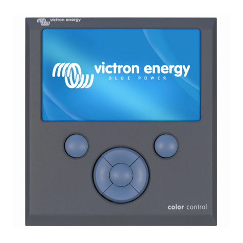
2.1. What is the Color Control GX?
The Color Control GX is a member of the GX product family and is operated using control buttons directly on the built-in LCD
display.
GX products are Victron's state-of-the-art monitoring and control solution that run our Venus OS operating system. It sits at the
heart of your energy installation. All the other system-components such as inverter/chargers, solar chargers, and batteries are
connected to it. The CCGX ensures that they all work in harmony.
To monitor and control your system, you can simply access it remotely via our Victron Remote Management (VRM) portal from
anywhere in the world using an internet connection. Or access it directly, using the control buttons at the integrated LCD display, a
web browser, a Multi-Functional Display (MFD) [73] or our VictronConnect app
The Remote Console [33] serves as the primary control center for monitoring, controlling and managing your system.
The CCGX also provides VRM: Remote firmware updates and allows settings to be changed remotely..
Note that all the information in this manual refers to the latest software. You can check your device has the latest version in
the firmware menu (see the Firmware updates [50] chapter) when the GX device is connected to the internet. For installations
without internet, you can find the latest version in Victron Professional.
2.2. What's in the box?
• Color Control GX
• Power cable with inline fuse and M8 terminal eyes for battery or DC busbar-attachment
• Product Specification Datasheet and overview of connections
• Mounting bracket and screws
• Snap on ferrite beads
• VE.Can terminators (2 pcs)
Color Control GX Manual
Page 2 Introduction

3. Installation
3.1. Color Control GX Overview of connections
Color Control GX Manual
Page 3 Installation

3.3. Powering the Color Control GX
The device is powered by using the Power in V+ connector. It accepts 8 to 70V DC. The device will not power itself from any of
the other connections (eg network). The supplied DC power cable includes an inline 3.15A slow blow fuse.
When the CCGX is used in an installation with a VE.Bus BMS, connect the Power in V+ on the CCGX to the terminal labelled
'Load disconnect' on the VE.Bus BMS. Connect both negative leads to the negative stub of a common battery.
A cautionary word about powering from the AC-out terminal of a VE.Bus Inverter, Multi or Quattro:
If you power the CCGX from an AC adaptor connected to the AC-out port of any VE.Bus product (Inverter, Multi or Quattro), then
a deadlock will occur after the VE.Bus products are powered-down for any reason (after any operational fault or during a black
start). The VE.Bus devices will not boot-up until the CCGX has power …but the CCGX will not boot-up until it has power. This
deadlock can be rectified by briefly unplugging the CCGX VE.Bus cable at which point you will observe the VE.Bus products will
immediately begin to boot-up.
Or a modification can be done to the RJ45 cabling. See FAQ Q20 [112] for more information about this.
Note that both with or without above modification, powering the monitoring equipment with the AC-out of an inverter/charger (of
course) has the disadvantage that all monitoring is shut down when there is a problem that causes the inverter/charger to shut
down. Examples are inverter overload, high temperature or low battery voltage. It is therefore recommended to power the GX
device from the battery.
Isolation
Because the CCGX is connected to many different products, please ensure that proper care is taken with isolation to prevent
ground loops. In 99% of installations this will not be a problem.
• VE.Bus ports are isolated
• VE.Direct ports are isolated
• VE.Can ports are isolated
• USB ports are not isolated. Connecting a WiFi Dongle or GPS Dongle will not create a problem as it is not connected
to another power supply. Even though there will be ground loop when you mount a separately-powered USB hub, during
extensive testing we have not found that it caused any issues.
• The Ethernet port is isolated, except for the shield: use unshielded UTP cables for the Ethernet network.
Extending USB ports by use of a self-powered USB hub
Although the number of USB ports can be extended by using a hub, there is a limit to the amount of power that the onboard USB
port can provide. When extending the number of USB ports, we recommend you always use powered USB hubs. And to minimize
the chance of issues, be sure to use good-quality USB hubs. As Victron also offers a VE.Direct to USB adapter, you can use this
arrangement to increase the number of VE.Direct devices you can connect to your system, please see this document for the limit
of how many devices can be attached to various different GX devices.
3.3.1. Snap-on ferrite beads for class B EMI compliance
In order to reduce Electromagnetic emissions in compliance with class B EMI you should place the provided snap-on ferrite beads
around every connection cable as close as possible to the Color Control.
HQ1700 and later
For serial numbers HQ1700 and later, mount a single snap-on ferrite bead (supplied with the unit) around the power leads like
this:
HQ1654 and earlier
For serial numbers HQ1654 and earlier, mount the snap-on ferrite beads as below:
Color Control GX Manual
Page 5 Installation

Color Control GX Manual
Page 6 Installation

3.4. Relay connections
The Color Control GX has potential-free Normally Open (NO) relay functionality. The function of the relay can be set via the GX
menu, Settings → Relay → Function.
In addition to manual and temperature [48]-related triggering, it can also be used as an alarm [37], generator start/stop [100] or
tank pump [37] relay.
If the relay function is configured as an Alarm relay, it is possible to reverse the polarity of the relay via an additional menu. The
default setting is Normally open. Please note that reversing the polarity to Normally closed will result in a slightly higher current
consumption of the GX device.
Color Control GX Manual
Page 7 Installation

4. Connecting Victron products
4.1. VE.Bus Multis/Quattros/Inverters
In order to keep this document short we are going to refer to all Multis, Quattros and Inverters as VE.Bus products.
The earliest version of VE.Bus devices that can be connected using the Products: Product_Acronym is 19xx111, where the first 2
digits represent the microprocessor and the last 3 digits represent the VE.Bus firmware version.
VE.Bus device microprocessor GX device support
18xxxxxx No
19xx111 Yes
20xx111 Yes
26xxxxx Yes
27xxxxx Yes
Note that for Multis, Quattros and EasySolars, it is not possible to use the Remote On/Off (header on the VE.Bus control PCB) in
combination with a CCGX. There should be a wire between the left and middle terminal, as it is when shipped from the factory. In
case a wired switch that disables the system is required, use the Safety Switch Assistant instead.
This limitation does not apply to the next generation of VE.Bus inverter/chargers: when using a MultiPlus-II, Quattro-II or
EasySolar-II, the Remote on/off terminal header *can* be used in combination with Color Control GX.
Before connecting any VE.Bus product, be very careful not to confuse the GX device VE.Bus ports
with the Ethernet or VE.Can/BMS-Can port!
Single VE.Bus products
To connect a single VE.Bus product, connect it to one of the VE.Bus sockets on the back of the CCGX. Both sockets are identical,
use either one. Use a standard RJ45 UTP cable, see our pricelist.
Parallel, split- and three-phase VE.Bus systems
To connect multiple VE.Bus products, configured as a parallel, split-phase or three-phase VE.Bus system, connect either the first
or the last VE.Bus product in the chain to either one of the VE.Bus sockets on the back of the CCGX. Use a standard RJ45 UTP
cable, see our pricelist.
Systems consisting of five or more VE.Bus products, connected to a CCGX with serial number HQ1628 or earlier require the
CCGX dongle for large VE.Bus systems (Product Number: BPP900300100).
VE.Bus systems with Lithium batteries and a VE.Bus BMS
• The following only applies to the VE.Bus BMS v1, not to be confused with its successor VE.Bus BMS V2.
• Connect the CCGX to the socket labelled ‘MultiPlus/Quattro’, or to one of the Multis/Quattros in the system. Do not connect it to
the Remote panel socket on the VE.Bus BMS.
• Note that it will not be possible to control the On/Off/Charger Only switch. This option is automatically disabled in the CCGX
menu when a VE.Bus BMS is used. The only way to control a Multi or Quattro when used with a VE.Bus BMS is to add a Digital
Multi Control to the system. Setting the input current limit is possible in systems with a VE.Bus BMS.
• Combining MultiPlus/Quattro with a VE.Bus BMS and a Digital Multi Control is possible. Simply connect the Digital Multi Control
to the RJ-45 socket on the VE.Bus BMS labelled Remote panel.
• To allow auto-power-down in the CCGX in case of a low battery, make sure the CCGX is powered via the VE.Bus BMS:
connect Power in V+ on the CCGX to Load disconnect on the VE.Bus BMS. And connect both negative leads to the negative
stub of a common Battery.
Combining the CCGX with a Digital Multi Control
It is possible to connect both a CCGX and a Digital Multi Control to a VE.Bus system. The ability to switch the product On, Off
or set it to Charger Only via the CCGX will be disabled. The same applies to the input current limit: when there is a Digital Multi
Control in the system, the input current limit which is set at that control panel will be the master-setting, and changing it on the
CCGX will not be possible.
Color Control GX Manual
Page 8 Connecting Victron products

Connecting multiple VE.Bus systems to a single CCGX
Only one VE.Bus system can be connected to the VE.Bus ports on the back of the CCGX. The professional way to to monitor
more systems is to add a second CCGX
If you do require to connect more than one system to the same CCGX, use an MK3-USB. Functionality will be limited:
• Only the system connected to the built-in VE.Bus ports is used to generate the data on the Overview pages.
• All connected systems will be visible on the Device List.
• All connected systems will be taken into account for Energy consumption and distribution calculations (kWh graphs on VRM).
• Only the system connected to the built-in VE.Bus ports is used for the Generator start/stop logic.
• Only the Multi/Quattro (which can be a single device, or multiple together configured for three-/split-phase as well as parallel)
connected to the VE.Bus port will be controlled via DVCC. Additional systems, connected to the GX device using an MK3-USB,
are not controlled by DVCC and will charge and discharge according to the configuration made in those units.
• The CCGX will not send proper data to VRM any more. The Venus GX does send information of both systems to VRM: its
therefor better to use a Venus GX for systems like this.
• In case of an ESS system, only the system connected to the built-in VE.Bus ports is used in the ESS mechanisms. The other
one is displayed in the Device List only.
Alternatively the VE.Bus to VE.Can interface (ASS030520105) can be used. Add one for each additional system. Note that we
advise against it; this interface is a deprecated product. Make sure that the VE.Can network is terminated and powered. For
powering the VE.Can network, see Q17 in our data communication whitepaper.
Additional features provided by a GX device to VE.Bus products
An internet connected GX device allows for remote configuration via the VRM Portal. Please read the Remote VE.Configure
manual for more information, system requirements and specific steps to access this feature.
The internet connected GX device also allows remotely updating the firmware of VE.Bus products. For details see the Remote
VE.Bus firmware updates manual.
4.2. AC load monitoring
All energy meter types can be assigned the AC meter role. This is done in Settings → Energy meters → [your_energy_meter]
→ Role menu where you choose between Grid, PV Inverter, Generator and AC meter. With AC meter selected, the load will be
shown in the Device list and on VRM in the advanced widgets.
Please note that such metered loads are not used in any calculations, just monitoring.
4.3. Battery Monitor SmartShunt, BMV-700 series; and MPPTs with a VE.Direct
port
Direct connection via a VE.Direct cable is limited to the number of VE.Direct ports on the device (see Overview of
Connections [3]). There are two types of VE.Direct cables available:
1. Straight VE.Direct cables, ASS030530xxx
2. VE.Direct cables with an angled connector on one end. These are designed to minimise the required depth behind a panel,
ASS030531xxx
VE.Direct cables have a maximum length of 10 metres. It is not possible to extend them. If longer lengths are required, use a
VE.Direct to USB interface with an active USB extension cable.
Color Control GX Manual
Page 9 Connecting Victron products

It is also possible to use the VE.Direct to VE.Can interface, but note that this only works for BMV-700 and BMV-702. Not for the
BMV-712, MPPT solar chargers and Inverters with a VE.Direct port. See next paragraph for more information on that VE.Can
interface.
Connecting more VE.Direct devices to your Color Control GX than number of VE.Direct Ports
First of all, note that the maximum of VE.Direct devices that can be connected is GX device specific, and constrained by the CPU
power. It may also be reduced for very complex systems, such as many AC PV inverters or synchronised inverter chargers, etc.
So always allow some additional headroom in the design. How they are connected, whether via VE.Direct, via USB or USB hub,
does not change this maximum. See the Victron GX product range for the maximum limit on all GX devices.
For the CCGX, this limit is 5.
Options to connect more VE.Direct products than available VE.Direct ports:
1. Use the VE.Direct to USB interface. The CCGX has built-in USB ports. Use a USB-hub when additional USB ports are
required.
2. (Only!) the BMV-700 and BMV-702 can also be connected using the VE.Direct to VE.Can interface. Note that the BMV-712,
MPPTs and VE.Direct Inverters cannot be connected using this CAN-bus interface as it does not translate their data into
CAN-bus messages. When using the VE.Direct to VE.Can interface, make sure that the VE.Can network is terminated, and
also powered. For powering the VE.Can network, see Q17 in our data communication whitepaper. Lastly, note that this
CAN-bus interface is deprecated.
Notes about older VE.Direct MPPTs
• An MPPT 70/15 needs to be from year/week 1308 or later. Earlier 70/15s are not compatible with the CCGX , and unfortunately
upgrading the MPPT firmware will not help. To find the year/week number of your model, look for the serial number which is
printed on a label on its back. For example number HQ1309DER4F means 2013, week 09.
4.3.1. DC load monitor mode
If you wish to use a SmartShunt or BMV-712 to monitor individual DC circuits, rather than as a whole-of-system battery monitor,
you can change the Monitor mode setting from Battery Monitor to DC Energy Meter in VictronConnect.
If DC meter is selected, you can then select the following types (also in VictronConnect):
Solar charger, Wind charger, Shaft generator, Alternator, Fuel cell, Water generator, DC-DC charger, AC charger, Generic source,
Generic load, Electric drive, Fridge, Water pump, Bilge pump, DC system, Inverter, Water heater
Once connected to the Color Control GX, the type and the amps and power of the DC load is shown in the user interfaces and
available on the VRM Portal.
When configured as type “DC System”, the CCGX does more than just recording and visualisation:
1. The power shown in the DC system box is the sum of power reported by all SmartShunts configured as such. Allowing
multiple meters is done to accommodate for example a catamaran, so you can measure the DC Systems on Port hull and on
Starboard hull.
2. The DC system current is being compensated for when setting DVCC charge current limits to Multis, Quattros and Solar
Chargers. For example when a load of 50A is being measured, and CCL by the battery is 25A, the limit given to the Multis &
Solar Chargers is 75A. An improvement for systems with significant DC loads such as Yachts, Coaches and RVs.
Notes and limitations:
• This feature is available for SmartShunts and BMV-712. Not for BMV-700 or BMV-702.
• Setting the meter mode is done with VictronConnect, in the BMV/SmartShunt itself. For details see the BMV-712 or SmartShunt
product manual on the Battery Monitor product page.
• The NMEA2000-out feature does not support these new types, for example when using a SmartShunt to measure output of an
alternator, that data is not made available on NMEA 2000.
Color Control GX Manual
Page 10 Connecting Victron products

4.4. VE.Can Devices
To connect a product with a VE.Can port, use a standard RJ45 UTP cable (available with straight and elbow connectors).
Don't forget to terminate the VE.Can network at both ends using a VE.Can terminator. A bag with two terminators is supplied with
each VE.Can product. They are also available separately.
Other notes:
1. In order to work with the CCGX, an MPPT 150/70 must be running firmware v2.00 or newer.
2. You can combine a Skylla-i control panel with a CCGX.
3. You can combine a Ion Control panel with a CCGX.
4. All VE.Can devices power the VE.Can network, so it won't be necessary to power the VE.Can network separately in these
circumstances. All the protocol converters, for example the VE.Bus to VE.Can interface and the BMV to VE.Can interface, do
not power the VE.Can network.
The following VE.Can products also support VictronConnect-Remote (VC-R) – Configuration and monitoring via VRM. Please
read the VictronConnect manual for further details.
VE.Can product VC-R Remarks
Lynx Shunt VE.Can Yes -
Lynx Smart BMS Yes -
Inverter RS, Multi RS and MPPT RS Yes They also have VE.Direct but must be connected via VE.Can for
VC-R
Blue/Smart Solar VE.Can MPPTs [1] Yes Tr and MC4 models
Skylla-i and Skylla-IP44/-IP65 Yes Requires firmware v1.11
[1] All VE.Can solar chargers except the very old (big rectangular case with display) BlueSolar MPPT VE.Can 150/70 and
150/85
4.5. VE.Can Interfaces
The Color Control GX has one VE.Can interface that is electrically isolated.
VE.Can is intended to be used for Victron (and Victron compatible) VE.Can products, such as the VE.Can MPPTs, Skylla-IP65,
Lynx Shunt VE.Can and Lynx Smart BMS. You can string these VE.Can 250 kbit/s devices together along this bus. It must be
terminated at both ends with the included VE.Can terminators.
You can set the VE.Can port from 250 kbit/s to be 500 kbit/s (or one of several other CANbus speeds for other CANbus
applications).
By default; VE.Can is set to 250 kbit/s & BMS-Can (if present) to 500 kbit/s.
Other types of Batteries and BMS may claim compatibility with BMS-Can or VE.Can, but if they are not on the battery
compatibility list, then they have not been tested and confirmed to work by Victron.
One extra element of possible confusion is that there are some BMS products on the market that use a CANbus-BMS profile
at 250 kbit/s. These BMS products can only be connected to the VE.Can port, and it must also be set to match this (VE.Can &
CAN-bus BMS (250 kbit/s)) in the services menu for the VE.Can port. They can be used in the same cable daisy chain as other
Victron VE.Can devices.
4.6. Inverter RS, Multi RS and MPPT RS
The Inverter RS, Inverter RS Solar and Multi RS have both VE.Direct and VE.Can interfaces. For these specific products, it
is only possible to connect a GX device via the VE.Can interface. It is not possible to connect a GX device via the VE.Direct
interface.
The VE.Direct interface on these specific products is only used for connection of a VE.Direct to USB adapter for programming.
This restriction does not apply to the MPPT RS, which can be connected to a GX device via either VE.Direct or VE.Can.
4.7. BMV-600 series
• Connect the BMV-600 using the VE.Direct to BMV-60xS cable. (ASS0305322xx).
Color Control GX Manual
Page 11 Connecting Victron products

4.8. DC Link Box
• Connect the DC Link Box with the supplied RJ12 cable. Then connect the BMV-700 to the CCGX.
4.9. VE.Can Resistive Tank Sender Adapter
See the VE.Can resistive tank sender adapter product page for details about the adapter.
• To connect a product with a VE.Can port, use a standard RJ45 UTP cable
• Don't forget to terminate the VE.Can network on both ends using a VE.Can terminator. A bag with two terminators is supplied
with each VE.Can product. They are also available separately (ASS030700000). (Available with straight or elbow connectors).
• Make sure that the CAN-bus is powered, see the Power chapter in the Tank Sender Adapter manual for details.
4.10. Connecting a GX Tank 140
The GX Tank 140 is an accessory for our range of GX system monitoring products.
It takes readings from up to four tank level sensors.
Tank levels can be read-out locally in the system, as well remotely through our VRM Portal.
The GX Tank 140 is compatible with current senders (4 to 20mA) as well as voltage senders (0 to 10V). The connection to the GX
device is via USB, which is also how the GX Tank is powered: no additional power wires required.
To make wiring the tank sender as simple as possible, two of the four inputs provide a 24V power supply, to power the sender.
Using the other two channels requires an external power supply, and there is a power in terminal together with fused outputs to
facilitate that.
Upper and lower limits are configurable, to allow using senders that provide only part of the scale, for example 0 to 5V.
For marine applications, the GX device can transmit these tank levels on the NMEA 2000 network to be picked up by other
displays such as an MFD.
The GX Tank 140 product page links to the complete documentation of this product.
Color Control GX Manual
Page 12 Connecting Victron products

5. Connecting supported non-Victron products
5.1. Connecting a PV Inverter
Measuring the output of a PV Inverter will provide the user with an overview of both actual power balance and the energy
distribution. Note that these measurements are only used to display information. They are not needed nor used by the installation
for its performance. Besides monitoring, the GX device can also curtail some types and brands of PV Inverters, ie. reduce their
output power. This is used, and required, for the ESS Zero or limited feed-in feature.
Direct connections
Type Zero feed-in Details
Fronius Yes LAN Connection, see GX - GX - Fronius
manual
SMA No LAN Connection, see GX - GX - SMA manual
SolarEdge No LAN Connection, see GX - SolarEdge manual
ABB Yes LAN Connection, see GX - ABB manual
Using a meter
For PV Inverters that cannot be interfaced digitally, a meter can be used:
Type Zero feed-in Details
AC Current
Sensor
No Connected to inverter/charger analog input.
Lowest cost - least accurate. Energy Meter
Energy Meter
No Wired to the CCGX, or connected wirelessly
using our Zigbee to USB/RS485 convertes.
See the Energy Meters start page
Wireless AC
sensors
No See the Wireless AC Sensor manual -
Discontinued product
5.2. Connecting a USB GPS
Use a GPS to remotely, on the VRM Portal, track vehicles or boats. Also its possible to configure a Geofence, which will
automatically send an alarm when the system leaves a designated area. And gps-tracks.kml files can be downloaded to open
them e.g. in Navlink and Google Earth.
Victron does not sell USB-GPS modules, but the CCGX support third-party GPS modules which use the NMEA0183 command-
set - almost all do. It can communicate at both 4800 and 38400 baud rates. Plug the unit into either of the USB sockets.
Connection may take a few minutes, but the CCGX will automatically recognize the GPS. The unit's location will automatically be
sent to the VRM online portal and its position is shown on the map.
The CCGX has been tested for compatibility with:
• Globalsat BU353-W SiRF STAR III 4800 baud
• Globalsat ND100 SiRF STAR III 38400 baud
• Globalsat BU353S4 SiRF STAR IV 4800 baud
• Globalsat MR350 + BR305US SiRF STAR III 4800 baud
Color Control GX Manual
Page 13
Connecting supported non-Victron
products

5.3. Connecting a NMEA 2000 GPS
Instead of a USB GPS, a NMEA 2000 GPS can be used for remote vehicle or boat tracking in the VRM portal.
The third party NMEA 2000 GPS sender must meet the following requirements:
• The NMEA 2000 device class must be 60, Navigation.
• The NMEA 2000 device function must be 145, Ownship Position (GNSS).
• Position (latitude, longtitude) must be transmitted in PGN 129025.
• Height, which is optional, must be transmitted in PGN 129029.
• Course and speed (both optional), must be transmitted in PGN 129026.
Most NMEA 2000 GPS-es are expected to work. Compatibility has been tested with:
• Garmin GPS 19X NMEA 2000
To connect a NMEA 2000 network to the VE.Can port on the GX device, which both have a different style connector, there are two
solutions:
1. The VE.Can to NMEA2000 cable. Which by either inserting or leaving out the fuse allows to either power the NMEA 2000
network with Victron equipment, or not. Take note of below warning.
2. The 3802 VE.Can Adapter by OSUKL. Its advantage is that it lends itself well to connecting a single NMEA 2000 device such
as a tank sender into a VE.Can network. It's also able to power a lower voltage NMEA 2000 network directly from a 48V
Victron system.
Warning and solution for 24V and 48V systems
Whilst all Victron components accept up to 70V input on their CAN-bus connections, some NMEA 2000 equipment does not. They
require a 12V powered NMEA 2000 connection, and sometimes work up to 30 or 36V. Make sure to check the datasheet of all
used NMEA 2000 equipment. In case the system contains NMEA 2000 that requires a network voltage below the battery voltage,
then either see above 3802 VE.Can Adapter by OSUKL, or alternatively install the VE.Can to NMEA 2000 cable without it’s fuse,
and provide suitable power to the NMEA 2000 network using for example a NMEA 2000 power adapter cable – which is not
supplied by Victron. The VE.Can port on the GX device does not need external power to operate.
5.4. Connecting a Fischer Panda Generator
See GX - Fischer Panda generators.
5.5. Connecting third-party NMEA 2000 tank senders
A third-party NMEA 2000 tank sender must meet the following requirements to be visible on the GX device:
• Transmit the NMEA 2000 Fluid Level PGN, 127505
• The NMEA 2000 device class needs to either General (80) in combination with function code Transducer (190), or Sensor
(170). Or, the NMEA 2000 device class needs to be Sensors (75), in combination with function Fluid Level (150).
A single function reporting multiple Fluid Levels is currently not supported.
For some tank senders it is also possible to configure the capacity and the fluid type on the GX Device menus - for example the
Maretron TLA100. This facility may be available with other senders made by other manufacturers - it's well-worth trying.
Tested compatible NMEA 2000 tank senders:
• Maretron TLA100
• Maretron TLM100
• Navico Fluid Level Sensor Fuel-0 PK, partno. 000-11518-001. Note that you need a Navico display to configure the Capacity,
Fluid type, and other parameters of the sensor. See voltage warning below.
• Oceanic Systems (UK) Ltd (OSUKL) - 3271 Volumetric Tank Sender. In case it doesn’t work, it needs a firmware update.
Contact OSUKL for that. See voltage warning below.
• Oceanic Systems UK Ltd (OSUKL) - 3281 Water Level Sender. See voltage warning below
Most likely others work as well. If you know of one working well, get in touch with us on Community -> Modifications.
To connect an NMEA 2000 network to the VE.Can port on the GX device, which both have different type connectors, there are
two solutions:
Color Control GX Manual
Page 14
Connecting supported non-Victron
products
Other manuals for Color Control GX
7
This manual suits for next models
2
Table of contents
Other Victron energy Control Unit manuals

Victron energy
Victron energy Smart BMS CL 12/100 User manual

Victron energy
Victron energy Color Control GX User manual

Victron energy
Victron energy Venus GX User manual

Victron energy
Victron energy VE.Bus BMS V2 User manual

Victron energy
Victron energy Venus GX User manual

Victron energy
Victron energy Color Control Use and care manual

Victron energy
Victron energy GlobalLink 520 User manual

Victron energy
Victron energy BlueSolar Pro User manual

Victron energy
Victron energy Lynx Shunt VE.Can User manual

Victron energy
Victron energy Venus GX User manual