66251115 - V5.0 - 30/09/21
- 7 -
6200 Series
Art.6296 - Installation instructions
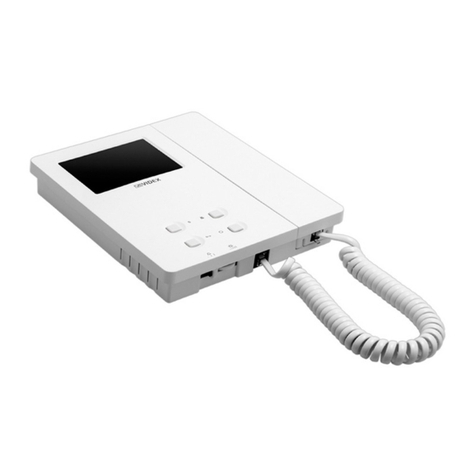
Art.6296 3.5" touch screen videophone for IPure system
ENABLE OR DISABLE MICROPHONE
1. Tap icon to disable the microphone
2. Tap again to enable it.
Microphone enabled
Microphone disabled
Note: this option is available only when
you pick up the handset.
TAKE A SNAPSHOT
By default, on every videocall or camera
recall, the device takes a snapshot auto-
matically.
If you tap icon the snapshot will be over-
written.
To see the snapshot go to Event log
and tap the related event. For details see
“Event log”on page 3.
REJECT OR CLOSE THE CALL
Tap to reject or close the call
INTERCOMMUNICATING CALL
During a call coming from an indoor station you’re able to make the following
operations and adjustments:
Enable or disable microphone
Reject or close the call
ENABLE OR DISABLE MICROPHONE
1. Tap icon to disable the microphone
2. Tap again to enable it.
Note: this option is available only
when you pick up the handset.
Microphone enabled
Microphone disabled
REJECT OR CLOSE THE CALL
Tap to reject or close the call Fig. 16
INPUTS/OUTPUTS OPERATION AND TACTILE PROGRAMMABLE PUSH BUTTONS
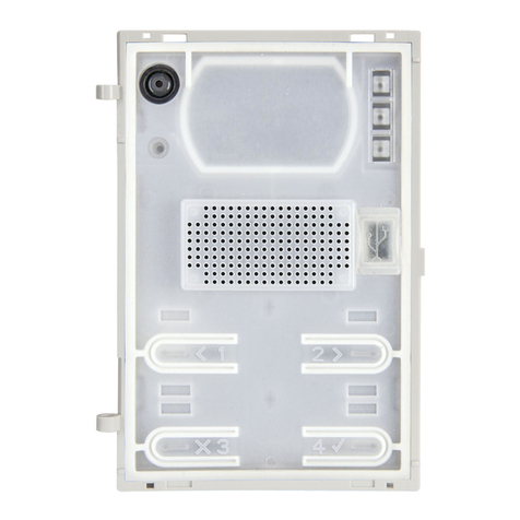
The operation of the input/output terminals and the four tactile buttons (Fig. 1 B) are fully programmable using the programming
software VX IP Wizard.
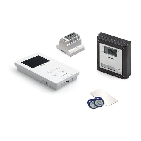
FACTORY DEFAULT PROCEDURE FOR VIDEOPHONES SUPPLIED WITH VIDEOKITS
The following procedure can be used to reset and pair the vid-
eophone and entrance panel supplied in a one apartment or
two apartment kit. Once paired the door panel will call the vid-
eophones without any further setup required. Additional setup
is optional to set device names, specic IP addresses etc. The
default IP addresses are:
Entrance panel: 192.168.1.180
Videophone 1: 192.168.1.181
Videophone 2: 192.168.1.182
VIDEOPHONE RESET FOR ONE OR TWO APARTMENT
VIDEO KIT
The videophone is required to be open for this procedure.
1. Power down the videophone
2. Restore the power keeping pressed the and buttons
(Fig. 17) until the and LEDs start ashing together (Fig. 18)*
3. To setup which videophone is the rst and which is second, press
and keep pressed one of the following buttons until only the rel-
evant LED remains ON:
• The button for the rst monitor of a one way or two
way video kit (Fig. 19)
• The button for the second monitor of a two way video
kit (Fig. 20)
4. When the button is released, the monitor emits one long
beep (videophone one) or two long beeps (videophone two)
then reboots with the new settings.
* If the monitor is connected to the cloud , the LED ashes twice then the videophone
will reboot without changing the settings, In this case, the IP wizard must be used to make any
changes to the videophone settings.
Fig. 17 Press and keep
pressed
Fig. 18 Release the buttons
when the LEDs start ashing
Fig. 19 Videophone 1 of a one
or two way videokit
Fig. 20 Videophone 2 of a two
way videokit
