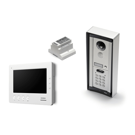
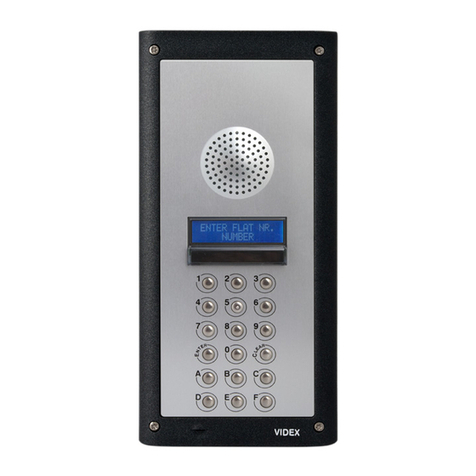
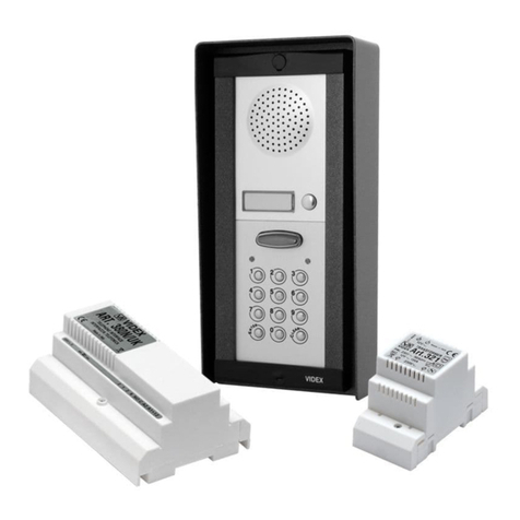
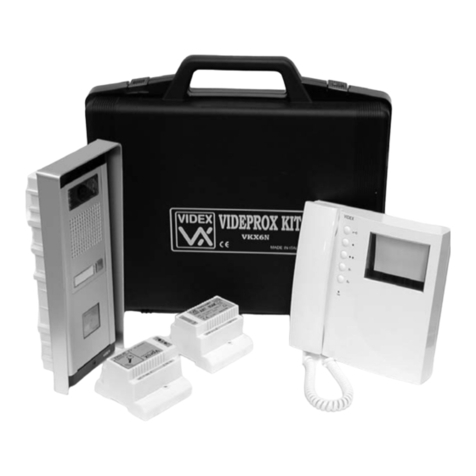
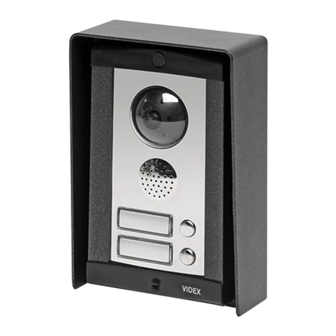
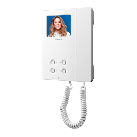
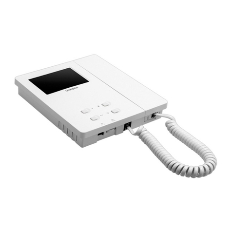
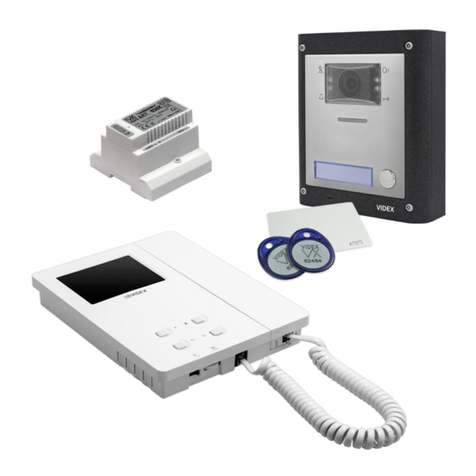
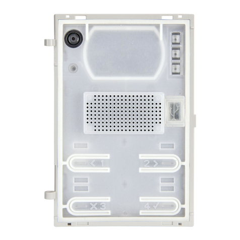
Videx Audiokit 4K Series User manual

66550016 - V4.2 - 15/11/20
- 1 -
Audiokit 4K Series
Audiokit 4K Series - Installation instructions
Rev.0.1
GENERAL DIRECTIONS FOR INSTALLATION
In order to achieve the best results from the schematics described it is necessary to install only original VIDEX equipment, strictly
keeping to the items indicated on each schematic and follow these General Directions for Installation:
• The system must be installed according to national rules in force, in any case the running of cables of any intercom unit must be
carried out separately from the mains (see the next paragraph for connection to mains and power supply installation);
• All multipair cables should be compliant to CW1308 specication (0.5mm twisted pair telephone cable);
• Cables for speech line and service should have a max resistance of 10Ω;
• Lock release wires should be doubled up (Lock release wires and power supply wires should have a max resistance of 3Ω);
• The cables sizes above can be used for distances up to 50m. On distances above 50m the cable sizes should be increased to keep
the overall resistance of the cable below the RESISTANCES indicated above;
• Double check the connections before power up; 3 Power up the system then check all functions.
CONNECTION TO MAINS AND POWER SUPPLY MOUNTING INSTRUCTIONS
The system must be installed according to national rules in force, in particular we recommend to:
• Connect the system to the mains through an all-pole circuit breaker which shall have contact separation of at least 3mm in each
pole and shall disconnect all poles simultaneously;
• The all-pole circuit breaker shall be placed for easy access and the switch shall remain readily operable.
POWER SUPPLY INSTALLATION
• Remove the terminal side covers by unscrewing the retaining screws;
• Fix the power supply to a DIN bar or directly to the wall using two expansion type screws;
• Switch othe mains using the circuit breaker mentioned above and then make the connections as shown on the installation diagrams;
• Check the connections and secure the wires into the terminals;
• Replace the terminal covers and x them using the relevant screws;
• When all connections are made, restore the mains.
Art.4K/3011-3012-3111-3102G
Audiokit

66550016 - V4.2 - 15/11/20
- 2 -
Audiokit 4K Series
Audiokit 4K Series - Installation instructions
Wiring Guide Line
All intercoms wiring must run separately from the mains cable.
The cable type should be CW1308 or an equivalent cable. The cable size should comply with the table below.
DISTANCE METERS CABLE SIZE (MM2)
50 0.35
100 0.5
200 0.75
300 1.0
400 1.5
Max resistance of all lines: 8 Ohm
Before powering the system up, the wiring should be double checked to ensure it complies with the wiring diagram supplied.
TROUBLE SHOOTING GUIDE
In the event of the system not functioning correctly when you power up, the following points can be checked (a multimeter will be
needed).
SYSTEM DEAD
• Check mains input to the transformer.
• Check the 12Vdc (+12 terminal) output from the power supply.
• Check fuses.
• Check for shorts on power supply wires.
SPEECH & LOCK WORKS BUT NO ELECTRONIC CALL TONE
• Check the link between Cand C1 terminals of the speaker unit.
• Call wire to terminal 4of the handset broken on in short circuit; check the walk of the call wire.
NO SPEECH FROM THE DOOR PANEL
• Check and/or adjust the volume operating on trimmers controls on rear of speaker unit.
• Check the wire from terminal 2of the speaker unit to terminal 2of the handset.
NO SPEECH FROM THE HANDSET
• Check and/or adjust the volume operating on trimmers controls on rear of speaker unit.
• Check the wire from terminal 1of the speaker unit to terminal 1of the handset.
LOCK DOES NOT WORK
• Check on the handset the link between terminals 1and 5.
• Check the 13Vac output on the transformer.
• Check the wires of the electric lock.
• Wires section not in conformity with the table above.
FEEDBACK PROBLEM (LARSEN EFFECT)
• Check that the handset microphone is rmly tted inside its housing.
• Check that the speaker unit microphone is rmly tted inside its housing and nothing is obstructing the microphone hole.
• Adjust the volume operating on trimmer controls on rear of the speaker unit.
HUM ON THE SPEECH LINES
• Check that system cables are not running close to any high voltage or mains cables.
• Check that the system is wired exactly as shown on the wiring diagram.
WE RECOMMEND THIS EQUIPMENT IS INSTALLED BY A COMPETENT ELECTRICIAN, SECURITY OR COMMUNICA-
TIONS ENGINEER.
If further assistance is required, call the technical help desk on 0191-2243174 for uk customers or +39 0734631669
for other countries.

66550016 - V4.2 - 15/11/20
- 3 -
Audiokit 4K Series
Audiokit 4K Series - Installation instructions
4000 Series Surface and ush mounting door station installation
EXAMPLE: INSTALLING A FOUR MODULE OUTDOOR STATION
H
G
H
Y
G
C
F
E
D
B
A
CL
H
L
P O
N
M
H
M
M
C
Q
P
C
D
W
N
N
C
H
g. 1
g. 8
g. 4 g. 5 g. 6 g. 7
g. 3
g. 10
g. 11
g. 15
g. 12
g. 16
g. 13
g. 17
g. 14
g. 18
g. 2
g. 9

66550016 - V4.2 - 15/11/20
- 4 -
Audiokit 4K Series
Audiokit 4K Series - Installation instructions
4000 Series Surface and ush mounting door station installation
INSTALLING A SURFACE MOUNT DOOR STATION
1. Place the surface box against the wall (165-170cm between the top of the box and the oor level as shown in Fig.1) and mark the xing holes for
the wall plugs and the hole for the cables E(g.2). Observe the orientation of the box with the hinge on the left;
In order to prevent water ingress we highly recommend using a silicon sealant between the wall and the back box C
ON THE LEFT, TOP AND RIGHT SIDES ONLY AND AROUND ALL HOLES D.
DON’T USE SILICON SEALANT ON THE BOTTOM SIDE OF THE BACK BOX (Fig.3);
2. As shown on Fig.2, drill the xing holes A,insert the wall plugs Band feed the cables Ethrough the surface box opening D, x surface
box Cto the wall using the screws F;
3. Apply the Ysilicon sealant on top of each module as shown in Fig.4;
4. Before installation of the module support frame, hook the modules Gto the support frame Has shown in Fig.5then, as shown in Fig. 6, t
the two anti-tampering locks Wfor each module (do the same for the second module support frame);
5. When you have more than one support frame, hook the support frame to the surface box starting from the left. For convenience we will described
how to attach the left frame but the same must be carried out for the right frame. As shown in Fig. 7, hook the module support frame H(complete
with modules) to the surface box Cmoving the frame as suggested from pointers. Ensure that the pivots L(Fig. 7) go inside the relevant housing
Mas shown in Fig. 8;
6. As shown on Fig. 9, pull back the module support frame Hwhile moving it slightly to the left as suggested by the pointers;
7. As shown in Fig. 10, open the module support frame Has suggested by the pointer, hook the hinge locks Nto the hinges M,make the
required connections using the screwdriver provided P(at blade end) and make the required adjustment by adjusting the settings (through
openings O) and adjust trimmers;
8. Repeat the same operations described above for the second module support frame (or for the third if available);
9. When the system has been tested and is working correctly, move back the module support frames carefully, x them to the surface box using the
screwdriver provided P(torx end) and the pin machine torx screws Q(Fig. 11). Note: do not over tighten the screws more than is necessary.
INSTALLING A FLUSH MOUNTING DOOR STATION
When ush mounting and the number of modules is greater than 3, the required back boxes need to be linked together (before embedding them
in the wall) as shown on Fig. 14, 15 and 16:
• Arrange the back boxes and remove knockouts to allow cables to be fed from one back box to the other;
• Hook the spacers to rst back box then hook the second back box to obtain the result shown on Fig. 16;
1. Protect the module support frame xing holes from dust then embed the back box into the wall (165-170cm between the top of the box and
the oor level as shown on the Fig. 1) feeding the cables E(Fig. 2) through a previously opened hole in the box. Observe the direction of the
box ensuring the hinge is on the left and take care that the box prole is in line with the nished wall prole;
In order to prevent water ingress we highly recommend using a silicon sealant between the module support frame
Hand the back box ON THE LEFT, TOP AND RIGHT SIDES ONLY.
DON’T USE SILICON SEALANT ON THE BOTTOM SIDE OF THE MODULE SUPPORT FRAME (Fig.12);
2. Continue from step 4of surface mounting instructions , but at step 7hook the hinge locks
N
as shown on Fig. 13.
Note: if additional holes are made in the surface box, oxidation problems may appear unless the unprotected metal is
coated with a protective paint.
NOTES
• The screwdriver’s blade has two sides, one at and one torx, to select one of them unplug the blade from the screwdriver body and plug it
into the required side.
• The example shows the use of only one back box bottom hole for wires, this is done to keep le drawings clear. Naturally the installer can use
the left hole or the right or both if required.
HOW TO REMOVE THE CARD NAME HOLDER
• To avoid damage to the module front plate, tape the side that will be in contact with the screwdriver blade;
• lnsert the screwdriver (at side) into the card-holder hole as shown in Fig. 17;
• Move the screwdriver to the left as shown in Fig. 18 to extract the card name holder;
• Edit the card name then replace it inside the holder and ret: insert the holder inside its housing from the left or right side then push the other
side until it clips into place.

66550016 - V4.2 - 15/11/20
- 5 -
Audiokit Serie 4K
Art.4K-1/2 - 4K-1S/2S - Istruzioni di installazione
Rev.0.1
Art.4K/3011-3012-3111-3102G
Audiokit
NORME GENERALI D’INSTALLAZIONE
Per eseguire una corretta installazione è necessario impiegare esclusivamente parti VIDEX, seguire con scrupolo quanto indicato
negli schemi di collegamento e tenere presenti le norme generali d’installazione:
• Realizzare gli impianti secondo le vigenti normative nazionali ed in ogni caso si consiglia di prevedere, per i conduttori dell’im-
pianto, una canalizzazione distinta da quella della linea elettrica (vedi paragrafo seguente per il collegamento alla linea elettrica
e l’installazione dell’alimentatore);
• Impiegare conduttori con sezioni tali da avere:
• resistenza complessiva inferiore a 10Ωper quelli della linea fonica e di comando;
• resistenza complessiva inferiore a 3Ωper quelli della serratura e di alimentazione;
• Vericare le connessioni prima di dare alimentazione all’impianto;
• Alimentare l’impianto ed eseguire il collaudo vericandone tutte le funzioni.
COLLEGAMENTO ALLA RETE ELETTRICA ED INSTALLAZIONE DELL’ALIMENTATORE
La realizzazione dell’impianto deve essere eseguita nel rispetto delle vigenti normative nazionali, in particolare si raccomanda di:
• Collegare l’impianto alla rete elettrica tramite un dispositivo di interruzione omnipolare che abbia una distanza di separazione
del contatto di almeno 3mm per ciascun polo e che sia in grado di disconnettere tutti i poli simultaneamente;
• Il dispositivo di interruzione omnipolare deve essere posizionato in un luogo tale da consentirne un facile accesso in caso di necessità.
INSTALLAZIONE DELL’ALIMENTATORE
• Rimuovere i coperchi copri-morsetti svitando le relative viti e tirandoli verso l’alto;
• Fissare l’alimentatore su barra DIN o direttamente a parete utilizzando le viti ed i relativi tasselli ad espansione forniti a corredo;
• Togliere la tensione di rete tramite il dispositivo sopra indicato ed eseguire le connessioni come previsto dagli schemi proposti (la
connessione verso la rete va eettuata in base alla tensione disponibile 127 o 230Vac).
• Vericare che non vi siano errori di connessione e che i li siano ben serrati nei morsetti;
• Inserire a scatto i coperchi copri-morsetti e ssarli tramite le relative viti;
• Eseguiti tutti i collegamenti, dare tensione all’impianto.

66550016 - V4.2 - 15/11/20
- 6 -
Audiokit Serie 4K
Art.4K-1/2 - 4K-1S/2S - Istruzioni di installazione
Guida ai cablaggi
Tutti i cablaggi devono essere passati separatamente dal cavo dell’alimentazione principale.
Il tipo di cavo da utilizzare deve essere CW1308 o equivalente. La sezione del cavo deve essere conforme alla tabella seguente:
DISTANZA IN METRI SEZIONE DEL CAVO (MM2)
50 0.35
100 0.5
200 0.75
300 1.0
400 1.5
Resistenza massima di tutte le linee: 8 Ohm
Prima di avviare il sistema, ricontrollare il cablaggio assicurandosi che sia conforme alle speciche indicate nello schema di connessione.
GUIDA AI PROBLEMI TECNICI
In caso di malfunzionamento del sistema , controllare i seguenti punti (occorre utilizzare un multimetro).
SISTEMA NON DA SEGNALE
• Controllare l’ingresso dell’alimentazione principale al trasformatore.
• Controllare l’uscita a 12Vdc (+12 terminal) dall’alimentatore.
• Controllare i fusibili.
• Controllare se c’è qualche corto sui li dell’alimentatore.
LA CONVERSAZIONE E SERRATURA FUNZIONANO MA NON C’E’IL TONO DELLA CHIAMATA ELETTRONICA
• Controllare la connessione tra i morsetti Ce C1 del portiere elettrico.
• Mettere in corto il cavo che va al morsetto 4del citofono non funzionante, controllare il passaggio dei li di chiamata.
NIENTE CONVERSAZIONE DAL POSTO ESTERNO
• Controllare e/o settare il volume azionando i trimmers nella parte posteriore del portiere elettrico.
• Controllare il cavo dal morsetto 1del portiere elettrico al morsetto 1del citofono.
NIENTE CONVERSAZIONE DAL CITOFONO
• Controllare il volume azionando i trimmers nella parte posteriore del portiere elettrico.
• Controllare il lo dal morsetto 1del portiere elettrico al morsetto 1del citofono.
LA SERRATURA NON FUNZIONA
• Controllare sul citofono la connessione tra i morsetti 1e 5.
• Controllare l’uscita 13Vac sul trasformatore.
• Controllare i li della serratura.
• La sezione dei cavi non è conforme alle speciche della tabella.
EFFETTO LARSEN
• Controllare che il microfono del citofono è ssato bene al suo posto.
• Controllare che il microfono del portiere elettrico è ssato bene al suo posto, e non ci siano ostacoli che ostruiscono il foro del
microfono.
• Settare il volume azionando i trimmers nella parte posteriore del portiere elettrico.
RONZIO NELLA LINEA DI CONVERSAZIONE
• Controllare che i cavi del sistema non passino vicino ai cavi dell’alimentazione principale o ad alto voltaggio.
• Controllare che il sistema sia collegato esattamente come illustrato nello schema di cablagggio.
SI RACCOMANDA DI FAR INSTALLARE LE APPARECCHIATURE DA UN INSTALLATORE PROFESSIONALE O DA UN
INGEGNERE.
In caso di ulteriore assistenza contattare il personale tecnico al numero +39 0734631669.

66550016 - V4.2 - 15/11/20
- 7 -
Audiokit Serie 4K
Art.4K-1/2 - 4K-1S/2S - Istruzioni di installazione
H
G
H
Y
G
C
F
E
D
B
A
CL
H
L
P O
N
M
H
M
M
C
Q
P
C
D
W
N
N
C
H
g. 1
g. 8
g. 4 g. 5 g. 6 g. 7
g. 3
g. 10
g. 11
g. 15
g. 12
g. 16
g. 13
g. 17
g. 14
g. 18
g. 2
g. 9
ESEMPIO DI INSTALLAZIONE POSTO ESTERNO A 4 MODULI
Serie 4000 Installazione posto esterno da supercie e da incasso

66550016 - V4.2 - 15/11/20
- 8 -
Audiokit Serie 4K
Art.4K-1/2 - 4K-1S/2S - Istruzioni di installazione
INSTALLAZIONE POSTO ESTERNO DA SUPERFICIE
1. Appoggiare la scatola da supercie alla parete (ci devono essere 165-170cm tra la parte alta della scatola e il terreno come mostrato in Fig.1)
e prendere i riferimenti per i fori di ssaggio tenendo conto che il gruppo di li E(Fig. 2) deve attraversare il foro D(Fig. 2) della scatola da
supercie. Se non indicato, il verso della scatola deve essere tale da lasciare la cerniera a sinistra;
Per prevenire inltrazioni d’acqua si consiglia vivamente di apporre del silicone tra il muro e la scatola da supercie
CSOLAMENTE SUL LATO DESTRO, SINISTRO E SUPERIORE E INTORNO AI FORI PREFORMATI D.
NON APPORRE IL SILICONE SUL LATO INFERIORE DELLA SCATOLA DA SUPERFICIE (Fig.3);
2. Come mostrato in Fig. 2, realizzare i fori di ssaggio A,inserire all’interno dei fori gli stop Be, facendo passare i cavi di collegamento E
attraverso il foro D, ssare la scatola da supercie e alla parete utilizzando le viti F;
3. Applicare la guarnizione adesiva Ysopra ogni modulo come mostrato in Fig. 4;
4. Prima di installare il supporto moduli, agganciare a quest’ultimo i moduli Gcome mostrato in Fig. 5 ed inserire per ciascun modulo, come
mostrato in Fig. 6, i fermi anti-erazione W(eseguire la stessa operazione per il secondo supporto moduli);
5. Quando sono necessari più di un supporto moduli, questi vanno agganciati alla scatola da supercie partendo da quello più a sinistra. Per praticità
verràdescritto come procedere con il supporto di sinistra, ma naturalmente le stesse operazioni valgono anche per quello di destra. Come mostrato
in Fig. 7, agganciare il supporto moduli H(completo di moduli) alla scatola da supercie C,muovendolo come suggerito dalle frecce. Fare atten-
zione che i perni L(Fig.7) si inseriscano nei relativi alloggiamenti Mcome mostrato in Fig.8;
6. Come mostrato in Fig. 9, tirare il supporto moduli Hindietro compiendo contemporaneamente un leggero movimento a sinistra come sug-
gerito dalle frecce;
7. Come mostrato in Fig. 10, aprire il supporto moduli Hcome suggerito dalla freccia, agganciare i fermi Ndelle cerniere agli alloggiamenti M,
collegare i li utilizzando il cacciavite fornito (lato piatto) a corredo ed agire sulle fessure Odei moduli o sui fori dei trimmer per le opportune
regolazioni;
8. Compiere le stesse operazioni sopra descritte anche per il secondo supporto moduli (o terzo se presenti);
9. Quando il sistema è stato testato ed è funzionante, procedendo a ritroso delicatamente, chiudere e ssare i supporti alle scatole da supercie utiliz-
zando il cacciavite P(lato torx) e le viti Qfomite a corredo (Fig. 11). Nota bene: non serrare le viti più del necessario.
INSTALLAZIONE POSTO ESTERNO DA INCASSO
Se l’installazione è da incasso e il posto esterno è composto da più di 3 moduli, occorre collegare le scatole da incasso (prima di murarle) come
mostrato nelle Fig. 14, 15 e 16:
• Preparare le scatole da incasso aprendo le nestre in corrispondenza degli alloggiamenti per i distanziali dal lato (sinistro, destro o entrambi in
caso di 3 o più scatole) in cui questi verranno agganciati;
• Inserire i distanziali nella prima scatola da incasso quindi agganciare la seconda ad ottenere il risultato di Fig. 16.
1. Dopo aver opportunamente protetto i fori di ssaggio del supporto moduli, murare la scatola da incasso (lasciare 165-170cm tra la parte alta
della scatola e il terreno) facendo passare il gruppo di li E(Fig. 2) attraverso uno dei fori (precedentemente aperto) sul fondo della scatola.
Se non indicato sul fondo della scatola. il verso deve essere tale da far rimanere la cerniera a sinistra. Fate attenzione anché la scatola venga
murata a lo muro nito;
Per prevenire inltrazioni d’acqua si consiglia vivamente di apporre del silicone tra il supporto moduli He la scatola
SOLAMENTE SUL LATO DESTRO, SINISTRO E SUPERIORE.
NON APPORRE IL SILICONE SUL LATO INFERIORE DEL SUPPORTO MODULI (Fig. 12);
2. Continuare dal passo 4dell’installazione da supercie, ma al passo 7agganciare i fermi delle cerniere
N
come mostrato in gura Fig. 13.
Nota bene: praticando dei fori aggiuntivi sulla scatola da supercie si può incorrere a fenomeni di ossidazione.
NOTE
• La lama del cacciavite fornito a corredo ha due punte, una piatta ed una torx. Slare la punta e reinserirla nel manico scegliendo il lato desiderato.
• L’e sem pi o mos tra l’ u tili z zo di un s o lo foro del la sca t o la da su per c ie pe r i l pas s aggio d ei li , q ues t o è s tato fa t to sol o p er prat i cit à e per rendere più
puliti i disegni. Naturalmente l’installatore può utilizzare a suo piacimento il foro di destra, quello di sinistra o entrambi per il passaggio dei li.
RIMOZIONE DEL PORTA CARTELLINO
• Per evitare ammaccature della placca frontale, proteggere il lato che verrà in contatto con la lama del cacciavite utilizzando una striscia di
nastro isolante;
• Inserire il cacciavite (lato piatto della lama) nell’apposita fessura del porta cartellino come mostrato in Fig. 17;
• Fare leva con il cacciavite come mostrato in Fig. 18 per rimuovere il porta-cartellino (fare attenzione a non ammaccare la placca);
• Modicare il cartellino e riporlo all’interno del porta-cartellino quindi riposizionare lo stesso al suo posto inserendolo nel suo alloggiamento
dal lato destro o sinistro e premendo il lato rimasto libero no all’aggancio (compiendo un movimento contrario a quello fatto per estrarlo).
Serie 4000 Installazione posto esterno da supercie e da incasso
66550016 - V4.2 - 15/11/20
- 9 -

66550016 - V4.2 - 15/11/20
- 10 -

66550016 - V4.2 - 15/11/20
- 11 -

66550016 - V4.2 - 15/11/20
- 12 -

66550016 - V4.2 - 15/11/20
- 13 -

66550016 - V4.2 - 15/11/20
- 14 -

66550016 - V4.2 - 15/11/20
- 15 -
DISPOSAL
In accordance with the Legislative Decree no. 49 of 14 March 2014 “Implementation of the Directive 2012/19/EU on
waste electrical and electronic equipment (WEEE)”.
The crossed-out bin symbol on the equipment or on the packaging indicates that when the product reaches the end
of its lifetime, it must be collected separately from mixed municipal waste. The user must, therefore, dispose of the
equipment at the end of its lifetime in the suitable waste collection centres or bring it to the retailer during the pur-
chase of a new equipment of equivalent type at the ratio of one-to-one. Furthermore, the user is allowed to dispose
of the WEEEs of very small size (domestic appliances without any external dimension exceeding 25 cm (9.84 inches)
for free to the retailers, without any purchase obligation. The correct waste disposal of the WEEEs contributes to their
reuse, recycling and recovery and avoids potential negative eects on the environment and human health due to the
possible presence of dangerous substances within them.
SMALTIMENTO
Ai sensi del Decreto Legislativo 14 marzo 2014, n° 49 “Attuazione della direttiva 2012/19/UE sui riuti di apparecchia-
ture elettriche ed elettroniche (RAEE)”.
Il simbolo del cassonetto barrato riportato sull’apparecchiatura o sulla sua confezione indica che il prodotto alla ne
della propria vita utile deve essere raccolto separatamente dagli altri riuti urbani misti. L’utente dovrà, pertanto, con-
ferire l’apparecchiatura giunta a ne vita presso gli idonei centri di raccolta dierenziata oppure riconsegnarla al riven-
ditore al momento dell’acquisto di una nuova apparecchiatura di tipo equivalente, in ragione di uno a uno. L’utente ha,
inoltre, la possibilità di conferire gratuitamente presso i distributori, senza alcun obbligo di acquisto, per i RAEE di pic-
colissime dimensioni (per le apparecchiature di tipo domestico con nessuna dimensione esterna superiore a 25 cm).
L’adeguata raccolta dierenziata dei RAEE contribuisce al loro riutilizzo, riciclaggio e recupero ed evita potenziali ef-
fetti negativi sull’ambiente e sulla salute umana dovuti alla eventuale presenza di sostanze pericolose al loro interno.
ÉLIMINATION
Conformément au décret législatif n ° 49 du 14 mars 2014 relatif à l’«Application de la directive 2012/19 / UE relative
aux déchets d’équipements électriques et électroniques (DEEE)».
Lesymbole dela poubellebarréesur l’équipement ou surson emballage indiqueque leproduiten n devie utile doitêtre
collecté séparément des autres déchets municipaux en mélange. L’utilisateur doit donc remettre l’équipement en n de
vieauxcentresdecollecteappropriésoulerestitueraurevendeurlorsdel’achatd’unnouveautyped’équipementéquiva-
lent,danslerapportdeunàun.Deplus,l’utilisateuralapossibilitédeconférergratuitementauxdistributeurs,sansaucune
obligation d’achat, de très petits DEEE (pour les appareils ménagers sans dimensions extérieures supérieures à 25 cm).
La collecte séparée adéquate des DEEE contribue à leur réutilisation, leur recyclage et leur valorisation et évite les
éventuels eets négatifs sur l’environnement et la santé humaine en raison de la présence possible de substances
dangereuses dans ceux-ci.
ELIMINACIÓN
De conformidad con el Decreto legislativo n. 49 de 14 de marzo 2014 “Aplicación de la Directiva 2012/19/UE relativa a
residuos de aparatos eléctricos y electrónicos (RAEE)”.
El símbolo del contenedor tachado indicado sobre los aparatos o sobre los embalajes señala que el producto al -
nal de su vida útil debe ser recogido separadamente de otros residuos municipales mezclados. Por tanto, el usuario
deberà conferir los aparatos al nal de su vida útil en los apropriados centros de recogida selectiva o devolverlos al
revendedor al momento de la compra de nuevos aparatos equivalentes, en una relación de uno a uno. Además, el
usuario tiene la posibilidad de entregar sin cargo a los distribuidores, sin ninguna obligación de compra, los RAEEs
muy pequeños (para electrodomésticos sin dimensiones externas superiores a 25 cm).
La recogida selectiva apropriada de los RAEEs contribuye a su reutilización, reciclaje y valorización y evita potenciales
impactos negativos sobre el medio ambiente y la salud humana debidos a la possible presencia de substancias peli-
grosas dentro de ellos.
VERWIJDERING
In overeenstemming met het Wetsbesluit nr. 49 van 14 maart 2015 “Implementatie van de Richtlijn 2012/19/EU inzake
afgedankte elektrische en elektronische apparaten (AEEA)”.
Het doorgekruiste vuilnisbaksymbool op het apparaat of de verpakking geeft aan dat het product aan het einde van
zijn levensduur niet samen met het gewone huisvuil weggegooid mag worden. De gebruiker moet het apparaat aan
het einde van zijn levensduur inleveren bij een gepast inzamelpunt of de winkel waar hij een nieuw apparaat van een
gelijksoortig type zal kopen. De gebruiker kan tevens AEEA’s van een zeer klein formaat (huishoudapparaten met een
buitenafmeting kleiner dan 25 cm (9,84 inch)) gratis en zonder enige aankoopverplichting bij handelaars inleveren.
Een juiste verwijdering van AEEA’s draagt bij tot hergebruik, recycling en terugwinning, en voorkomt potentiële ne-
gatieve eecten op het milieu en de menselijke gezondheid door de mogelijke aanwezigheid van gevaarlijke stoen.

MANUFACTURER
FABBRICANTE
FABRICANT
FABRICANTE
FABRIKANT
VIDEX ELECTRONICS S.P.A.
Via del Lavoro, 1
63846 Monte Giberto (FM) Italy
Tel (+39) 0734 631669
Fax (+39) 0734 632475
CUSTOMER SUPPORT
SUPPORTO CLIENTI
SUPPORTS CLIENTS
ATENCIÓN AL CLIENTE
KLANTENDIENST
VIDEX ELECTRONICS S.P.A.
www.videx.it - technical@videx.it
Tel: +39 0734-631669
Fax: +39 0734-632475
UK Customers only:
VIDEX SECURITY LTD
www.videxuk.com
Tech Line: 0191 224 3174
Fax: 0191 224 1559
Main UK oce:
VIDEX SECURITY LTD
1 Osprey Trinity Park
Trinity Way
LONDON E4 8TD
Phone: (+44) 0370 300 1240
Fax: (+44) 020 8523 5825
www.videxuk.com
Northern UK oce:
VIDEX SECURITY LTD
Unit 4-7
Chillingham Industrial Estate
Chapman Street
NEWCASTLE UPON TYNE - NE6 2XX
Tech Line: (+44) 0191 224 3174
Phone: (+44) 0370 300 1240
Fax: (+44) 0191 224 1559
Greece oce:
VIDEX HELLAS Electronics
48 Filolaou Str.
11633 ATHENS
Phone: (+30) 210 7521028
(+30) 210 7521998
Fax: (+30) 210 7560712
www.videx.gr
Danish oce:
VIDEX DANMARK
Hammershusgade 15
DK-2100 COPENHAGEN
Phone: (+45) 39 29 80 00
Fax: (+45) 39 27 77 75
www.videx.dk
Benelux oce:
NESTOR COMPANY NV
E3 laan, 93
B-9800 Deinze
Phone: (+32) 9 380 40 20
Fax: (+32) 9 380 40 25
www.videx.be
Dutch oce:
NESTOR COMPANY BV
Business Center Twente (BCT)
Grotestraat, 64
NL-7622 GM Borne
www.videxintercom.nl
info@videxintercom.nl
El producto lleva la marca CE que demuestra su conformidad y puede ser
distribuido en todos los estados miembros de la unión europea UE.
Este producto cumple con las Directivas Europeas 2014/30/EU (EMC);
2014/35/EU (LVD); 2011/65/EU (RoHS): marca CE 93/68/EEC.
Het product heeft de CE-markering om de conformiteit ervan aan te tonen en
is bestemd voor distributie binnen de lidstaten van de EU zonder beperkin-
gen. Dit product volgt de bepalingen van de Europese Richtlijnen 2014/30/EU
(EMC); 2014/35/EU (LVD); 2011/65/EU (RoHS): CE-markering 93/68/EEG.
Le produit est marqué CE à preuve de sa conformité et peut être distribué
librement à l’intérieur des pays membres de l’union européenne EU.
Ce produit est conforme aux directives européennes 2014/30/EU (EMC) ;
2014/35/EU (LVD) ; 2011/65/EU (RoHS): marquage CE 93/68/EEC.
The product is CE marked demonstrating its conformity and is for distribution
within all member states of the EU with no restrictions. This product follows
the provisions of the European Directives 2014/30/EU (EMC); 2014/35/EU
(LVD); 2011/65/EU (RoHS): CE marking 93/68/EEC.
Il prodotto è marchiato CE a dimostrazione della sua conformità e può essere
distribuito liberamente all’interno dei paesi membri dell’Unione Europea UE.
Questo prodotto è conforme alle direttive Europee: 2014/30/UE (EMC);
2014/35/UE (LVD); 2011/65/UE (RoHS): marcatura CE 93/68/EEC.
!"
#"$%&'()%*'
#+,-./0,"1!23#&'()%*4%"$#,56723#&'((%84%"$
9!"##:*%8;%""!
This manual suits for next models
4
Table of contents
Languages:
Other Videx Intercom System manuals

Videx
Videx KRA78 User manual

Videx
Videx 6200 Series User manual

Videx
Videx 8KC/3012 User manual

Videx
Videx 4000 Series User manual

Videx
Videx VK4K/6358 Series System manual

Videx
Videx Kristallo Series User manual

Videx
Videx Kristallo Series User manual

Videx
Videx GSM Lite 4000 Series User manual

Videx
Videx Art.8835 User manual

Videx
Videx 4843 User manual

Videx
Videx 2 Wire User manual

Videx
Videx 6286 User manual

Videx
Videx VRVK Series System manual

Videx
Videx 4000 Series User manual

Videx
Videx VR4K-2/CL User manual

Videx
Videx VK4KX System manual

Videx
Videx 4845 User manual

Videx
Videx 800 Series User manual

Videx
Videx VX2200 User manual

Videx
Videx VK8K System manual