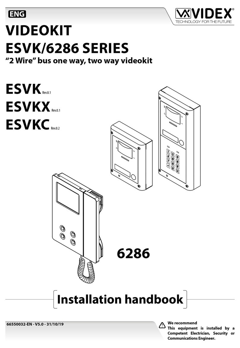
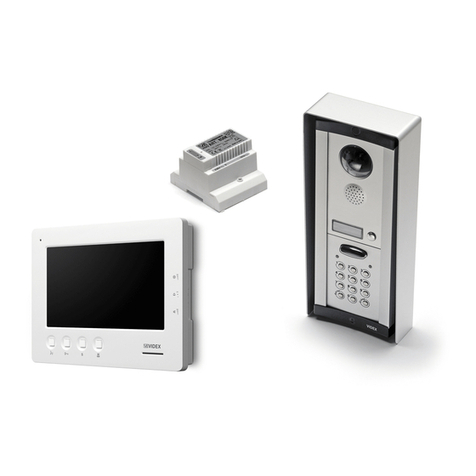
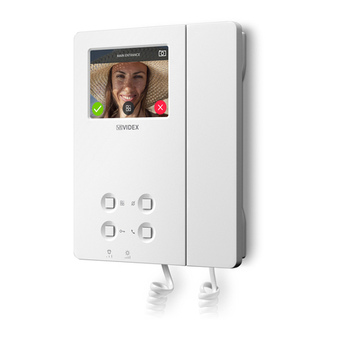
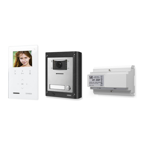
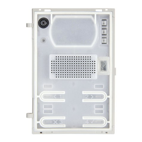
Videx 940ST User manual


CONTENTS
PAGE 2 - BLOCK DIAGRAM
PAGE 3-5 - INTRODUCTION & DESCRIPTION
PAGE 6 - SENTRY 1 PCB DIAGRAM
PAGE 7- SENTRY 1 PCB CONNECTIONS
PAGE 8 - ISOLATION PCB DIAGRAM
PAGE 9 - ISOLATION PCB DESCRIPTION
PAGE 10 - INSTALLATION & TESTING
PAGE 11 - TELEPHONE CHART
PAGE 12 - ACCESSORIES DIAGRAM
PAGE 13 - WIRING DIAGRAM (VR PANEL)
PAGE 14 - WIRING DIAGRAM (ISOLATION)
PAGE 15 - WIRING DIAGRAM (3 DOOR)
PAGE 16 - WIRING DIAGRAM (VIDEO)
PAGE 17 - TROUBLE SHOOTING GUIDE
PAGE 18 - VR PANEL LAYOUTS
PAGE 19 - USER INSTRUCTIONS (925MSL)
PAGE 20 - USER INSTRUCTIONS (940ST)


SENTRY 1 CONTROL UNIT
Introduction
The information in this manual is intended as an installation and
commissioning guide for the sentry 1 system. This manual should be read
carefully before the installation commences. Any damage caused to the
equipment due to faulty installations where the information in this manual has
not been followed is not the responsibility of VIDEX security UK LTD.
Description
The sentry 1 system can be used as a one or two door audio or video system.
The system comprises of the functional door panels (with the required
number of buttons), a control cabinet, a lock release for each door and the
required number of handsets. The following optional extras can also be used
with the sentry 1 system :-
Fireman's switch•
Busy light•
Codelock•
Sentrykey•
Push to exit•
Door monitoring•
Extension speaker•
Extension strobe•
Battery discharge cut off PCB•
Isolation PCB•
Video•
VproX proximity system•
The sentry 1 system is a two door functional door entry system which can be
expanded to control more doors with the use of additional sentry 1 control
PCB’s (One required for every two doors).
The Door panel can consist of any number of buttons. The vandal resistant or
Brass door panels can be used with this system. The door panel will also
include a diode board which is used to indicate to the control PCB which door
the call has come from. The door panel can also be extended to include
optional extras (i.e. codelock, sentrykey, video etc).
The 431/B control consists of a 24 hour analogue time clock, a 1 amp PSU
and the sentry 1 control PCB all within a lockable cabinet. (There is also
room within the cabinet for a back up battery (max - 12V 7AH).
The 531/B control cabinet contains the same items as the 431/B, but is IP55
rated.
There is a large range of compatible audio Handsets the system will work
with, these are listed in this manual.

Videophones are available with door open button and spare services button.
Other options may be available on request.
The heart of the system is the sentry 1 control PCB, which has the following
features :-
12V DC operation3
Voltage free contacts for the lock outputs. (Double pole 5A 30VDC)3
Timed calltone, speak time and lock open time :-3
CALLTONE LENGTH
SW1 SW2 TIME
ON OFF 1 SECONDS
OFF ON 2 SECONDS
OFF OFF 4 SECONDS
ON ON 8 SECONDS
SPEECH LENGTH
SW3 SW4 TIME
ON OFF 16 SECONDS
OFF ON 32 SECONDS
OFF OFF 60 SECONDS
ON ON 120 SECONDS
LOCK OPEN TIME
SW5 SW6 TIME
ON OFF 2 SECONDS
OFF ON 8 SECONDS
OFF OFF 16 SECONDS
ON ON 40 SECONDS
Timeclock input3
Trade button input3
Busy light output3
Engaged output (for use with multiple door systems)3
Additionally, if video is required on the system an ART893/20 power supply
will be required. This power supply will supply a 20V DC output to both the
videophones and the camera and will be fitted within the control cabinet.
Operation :-
A call will be activated by a visitor pressing the desired flat number on the
door panel. A timed call tone will be heard at the occupants telephone. The
videophone will also switch on at this point for the flats with the video facility).
A reassurance call tone will also be heard at the door panel to indicate the
system has been activated. If the occupant does not answer the telephone,
the call will clear down. If the occupant does answer the telephone, the call
tone will stop as soon as the handset is lifted. A two way conversation can
now take place (This will time out after the preset time). If the occupant does
not want to let the caller into the building, the handset would be put back on
its cradle. If the occupier does want to let the caller into the building, the lock
button would be pressed and the door would open for the preset time. The
lock button will not work at any other time.
The trade buttons only works when the time clock is active. At this time when
a trade button is pressed the door will open for the preset time.

A busy light would be used when more than one door panel is connected to
the system. The busy light will illuminate when a call is activated at any door
panel.
The Sentry 1 PCB incorporates four LED's which are used to indicate what
state the PCB is in. These LED's are labeled D10, D11, D12, D13. They
relate to the following functions :-
D10 : When this is illuminated, the system is awaiting a call.
D11 : When this is illuminated, the system is busy.
D12 : When this is illuminated, the call is from door one.
D13 : When this is illuminated, the call is from door two.
The Sentry 1 PCB includes a link option (JPR1) which when in position A, the
system will only allow one call to be activated at anyone time. The system
must time out before another call can be registered. When the link is in
position B the system will allow another button to be pressed with out waiting
for the system to time out. (The link should only be fitted in position B when
the system is being tested or being used as a one door system).
VIDEX run training courses for engineers who have not installed the sentry 1
system before.
Technical help is also available on 0191 224 3174 during office hours (8:30 -
12:30 and 1:30 - 5:00).
Technical specification :-
Working voltage : 12V DC
Current (Quiescent) : 24mA
Current (During a call) : 195mA
Current (During door open) : 165mA (Not including lock)


Connections :-
JP1 - VIN + 12 VOLTS SUPPLY
- VOUT + 12 VOLTS OUT
- GND NEGATIVE SUPPLY
JP2 - CB BUTTON COMMONS
- 1 RECEIVE SPEECH (DOOR ONE)
- 2 TRANSMIT SPEECH (DOOR ONE)
- 3 SWITCHED + 12 VOLTS, AMP SUPPLY
- 4 NEGATIVE AMP SUPPLY
- A TRIGGER FROM DOOR ONE
JP3 - ENG ENGAGED OUTPUT (HIGH WHEN ENGAGED)
- 1 RECEIVE SPEECH (DOOR TWO)
- 2 TRANSMIT SPEECH (DOOR TWO)
- 3 SWITCHED + 12 VOLTS, AMP SUPPLY
- 4 NEGATIVE AMP SUPPLY
- A TRIGGER FROM DOOR TWO
JP4 - 1 TRANSMIT SPEECH PHONE CONNECTION
- 2 RECEIVE SPEECH PHONE CONNECTION
- 4(T) CALLTONE TO PHONES
- 5(P) LOCK TRIGGER FROM PHONES
- 7(-) NEGATIVE TO PHONES
- +12V 12 VOLTS SUPPLY TO PHONES
JP5 - TC1 TRADE BUTTON FOR DOOR ONE
- TC1 TRADE BUTTON FOR DOOR ONE
- TC2 TRADE BUTTON FOR DOOR TWO
- TC3 TIME CLOCK CONNECTION
JP6 - NO1 NORMALLY OPEN 1 (LOCK, DOOR 1)
- CO1 COMMON 1 (LOCK, DOOR 1)
- NC1 NORMALLY CLOSED 1 (LOCK, DOOR 1)
- NO2 NORMALLY OPEN 2 (LOCK, DOOR 1)
- CO2 COMMON 2 (LOCK, DOOR 1)
- NC2 NORMALLY CLOSED 2 (LOCK,DOOR 1)
JP7 - NO1 NORMALLY OPEN 1 (LOCK, DOOR 2)
- CO1 COMMON 1 (LOCK, DOOR 2)
- NC1 NORMALLY CLOSED 1 (LOCK, DOOR 2)
- NO2 NORMALLY OPEN 2 (LOCK, DOOR 2)
- CO2 COMMON 2 (LOCK, DOOR 2)
- NC2 NORMALLY CLOSED 2 (LOCK,DOOR 2)


4 WAY ISOLATION PCB
Description :-
One PCB required for every four handsets.•
Isolates the speech, lock and call lines with the use of relays.•
protects the +12v supply and door monitoring line with fuses.•
There are LED's on the isolation PCB to indicate which phone has been•
enabled.
All connections are via plugs.•
Operation :-
The selects from the call buttons all go to a separate outputs on JP6 (either
A,B,C or D). When one of these outputs goes high (i.e. with a call to that
output), a thyristor on the isolation PCB is triggered, which in turn energises
the relays for that handset. Each of the four outputs on the isolation PCB
have two relays which reconnects the connections on JP1 with the
connections on that phone output (either JP2, JP3, JP4 or JP5). The thyristor
is held on by the voltage on the SW+ terminal on JP1. This voltage is only
there when a call is in progress.
Technical specification
Number of users : 4
Input voltage : 12VDC
Current (Quiescent) : 0mA
Current (During call) : 47.6mA

Installation
The wiring diagrams in the manual should be followed carefully. heavy duty
conductors on wiring diagrams are shown heavily outlined, These wires
should be doubled up.
Lock release back EMF protection : A diode must be fitted across the
terminals on the lock release to suppress back EMF voltages. The diagram
below shows the polarity of the diode when fitted to the release.
+
-1N4002 +
-
12V DC
LOCK RELEASE
DI
O
DE
Cable size and type : When running cables for any intercom system, these
cables must be installed separately from the mains cables. All multipair
cables should be to CW1308 specification. (0.5mm twisted pair telephone
cable). Max resistance = 10 Ohm.
Lock release wires should be doubled up. Max resistance = 3 Ohm
The cables sizes above can be used for distances up to 100m. On distances
above 100m the cable sizes should be increased to keep the overall
resistance of the cable below the RESISTANCES indicated above.
Safety Note : The earth wire from the cabinet lid should be connected to the
cabinet base and then to the earth connection in the building. This should be
checked for continuity.
Testing the installation :-
Check all the connections have been made correctly and then power up.
Call all the apartments in turn. Check for call tone to the apartment, speech in
both directions and lock release.
If the volume of speech needs to be adjusted, this can be done by adjusting
the presets on the rear of the amplifier at the door panel. (Repeat the above
for door two).
If the call tone volume needs adjusting this can be done at each handset
(Jumper marked VOL).
Check the fireman switch (If fitted).
Set the time clock on, off times. Check the trade button only works when the
time clock is on.


This manual suits for next models
7
Table of contents
Other Videx Intercom System manuals

Videx
Videx VX2200 User manual

Videx
Videx Kristallo Series User manual

Videx
Videx 3000 Series User manual

Videx
Videx 3000 Series User manual

Videx
Videx 5188 User manual

Videx
Videx VX2200 User manual

Videx
Videx 3187 User manual

Videx
Videx 3000 Series User manual

Videx
Videx VK4K/6458 Series User manual

Videx
Videx 4836 User manual

Videx
Videx 3000 Series User manual

Videx
Videx Kristallo Series User manual

Videx
Videx VK4K/3656 Series System manual

Videx
Videx 5418 User manual

Videx
Videx KRV98 Instruction manual

Videx
Videx ESVKX System manual

Videx
Videx VR5178 User manual

Videx
Videx 5178N User manual

Videx
Videx 4000 Series User manual

Videx
Videx 8000 Series User manual