Viessmann Vitotronic 100 GC1 Guide

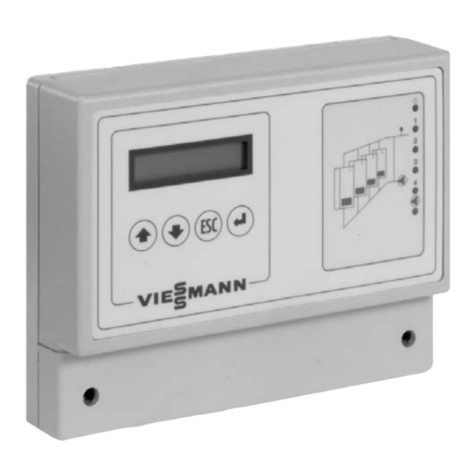
VITOCONTROL-S, VD2/CT3/CM2
Operating Instructions
and User’s Information Manual
Vitocontrol-S, VD2/CT3/CM2, Model 300-K, MW1
Outdoor-reset logic digital cascade control
Certified as a component part
of Viessmann boilers only
Please file in Service Binder
5351 341 v1 2 05/2012

Introductory information
2
For your safety
Please follow these safety instructions closely to avoid the risk of injury to persons and damage to property.
If you s ell gas
Don’t smoke! Don’t use naked
flames or cause sparks (e g by
switching lights or electrical
appliances on and off)
Open windows and doors
Close the gas shut-off valve
Inform your heating engineers/service
contractors from outside the building
Observe the safety regulations of
your gas supply company (see gas
meter) and those of your heating
engineers (see start-up or instruction
report)
In e ergencies
Immediately switch off the power
supply, e g at the separate fuse or
power supply disconnect switch
(unless there is a smell of gas)
Close the shut-off valves in the oil
pipes or close the gas shut-off valve,
whichever applicable
Use suitable extinguishers in the
event of fire
Work on the equip ent
Installation, initial start-up, maintenance
and repairs must be carried out by a
competent person (heating engineer/
service contractor)
Before work is undertaken on the
equipment/heating system, switch off the
power supply voltage (e g at the
separate fuse or power supply electrical
isolator switch) and take steps to prevent
it from being switched on again
Gas-fired systems: Also close the gas
shut-off valve and make secure to
prevent unauthorized use
Installation of additional co ponents
The installation of additional
components which have not been
tested together with the boiler can
adversely affect the function and
performance of the boiler
Our warranty does not cover and we
accept no liability for damage
attributable to the installation of such
components
Boiler roo conditions
Do not use a room in which the air
is polluted by halogenated
hydro-carbons (e g as contained in
aerosols, paints, solvents and
cleaning agents)
Do not use a room subject to high
levels of dust
Do not use a room subject to
permanently high humidity
The room should be frost-protected
Max ambient temperature 35 °C/
95 °F
Provide good ventilation and do not
close or obstruct vents (if installed)
This symbol indicates a
reference to other
instructions which must be
observed.
This header denotes special
instructions which apply to
the use of the Vitotronic 100,
G 1 in a multi-boiler system.
The ain controls
The settings required for operating your heating system are made on the
Vitotronic 100, GC1 of each boiler and on the Vitocontrol-S, VD2/CT3/CM2
If you system is equipped with remote controls, you can also use the remote
controls for some of the settings
See operating instructions for the remote control
The control unit is behind the hinged cover The hinged cover is opened by pulling
the top gently downwards towards you
You must close the hinged cover again after use
5351 341 v1 2
Multi-
boiler
syste
Index
3
Page
Useful tips
Introductory infor ation
For your safety 2, 4
Instructions in brief
Ready for operation
The main controls 2
Overview of controls and indicators 6
Vitotronic 100, GC1
Vitocontrol-S, VD2/CT3/CM2
Selecting the heating circuit - before every setting and scanning
operation (Vitocontrol-S, VD2/CT3/CM2)
Your heating system is preset 9
Selecting the heating program (winter, summer) 10
Changing the room temperature (Vitocontrol-S, VD2/CT3/CM2) 12
Reference guide
Switching on and off
Starting up the heating system 14
Shutting down the heating system 14
Settings
Changing the boiler water temperature (Vitotronic 100, GC1) 15
Selecting the time programs (Vitocontrol-S, VD2/CT3,CM2)
Setting the energy saving mode for the holiday period
(Vitocontrol-S, VD2/CT3/CM2)
Resetting the date and time (Vitocontrol-S, VD2/CT3/CM2)
Selecting the language (Vitocontrol-S, VD2/CT3/CM2)
Boiler sequence selection control (Vitocontrol-S, VD2/CT3/CM2)
Changing the heating pattern (Vitocontrol-S, VD2/CT3/CM2)
Scanning
Scanning temperatures and operating status information 28
Vitotronic 100, GC1
Vitocontrol-S, VD2/CT3/CM2
Infor ation
Troubleshooting guide
Diagnosis and correction 31
Vitotronic 100, GC1 31
Vitocontrol-S, VD2/CT3/CM2 33
5351 341 v1 2

Introductory information
4
For your safety
Please ensure that this anual is read and understood before co encing installation. Failure to co ply with the issues
listed below and details printed in this manual can cause product/property da age,severe personal injury, and/or loss of
life Ensure all requirements below are understood and fulfilled (including detailed information found in manual subsections)
Licensed professional heating
contractor
The installation, adjustment, service,
and maintenance of this equipment
must be performed by a licensed
professional heating contractor
Please see section
entitled “Important
Regulatory and
Installation
Requirements.”
Product docu entation
Read all applicable documentation be-
fore commencing installation Store
documentation near boiler in a readily
accessible location for reference in the
future by service personnel
For a listing of
applicable literature,
please see section
entitled “Important
Regulatory and
Installation Requirements.”
Advice to owner
Once the installation work is complete,
the heating contractor must familiarize
the system operator/ultimate owner
with all equipment, as well as safety
precautions/requirements, shut-down
procedure, and the need for
professional service annually before
the heating season begins
Warranty
Information contained in
this and related product
documentation must be
read and followed Failure
to do so renders warranty
null and void.
Safety Ter inology
The following terms are used throughout this manual to bring attention to the presence of potential hazards or important product
information Please heed the advice given!
Helpful hints for installation, operation
or aintenance which pertain to the
product.
5351 341 v1 2
Indicates an imminently hazardous
situation which, if not avoided, will
result in death, serious injury or
substantial product / property damage.
DANGER
Indicates an imminently hazardous
situation which, if not avoided, could
result in death, serious injury or
substantial product / property damage.
WARNING
Indicates an imminently hazardous
situation which, if not avoided, may
result in minor injury or product /
property damage.
CAUTION
IMPORTANT

Important Precautions
5
Safety
Take note of all sy bols and notations intended to draw attention to potential hazards or i portant product infor ation.
These include ”WARNING,” ”CAUTION,” and ”IMPORTANT”. See pages 2 and 4 for details.
Approvals
Viessmann boilers, burners and
controls are approved for sale in North
America by CSA International
Codes
The installation of this unit shall be in
accordance with local codes In the
absence of local codes, use:
CSA C22 1 Part 1 and/or local codes
in Canada
National Electrical Code ANSI/NFPA
70 in the U S
Always use latest editions of codes
Please carefully read this manual prior
to attempting installation. Any
warranty is null and void if these
instructions are not followed.
For information regarding other
Viessmann System Technology
componentry, please reference
documentation of the respective
product.
We offer frequent installation and
service seminars to familiarize our
partners with our products. Please
inquire.
Working on the equip ent
The installation, adjustment, service,
and maintenance of this product must
be done by a licensed professional
heating contractor who is qualified and
experienced in the installation, service,
and maintenance of hot water boilers
There are no user serviceable parts on
the boiler, burner, or control
Ensure ain power supply to
equipment, the heating system, and all
external controls has been deactivated
Close main oil or gas supply valve
Take precautions in both instances to
avoid accidental activation of power
during service work
The completeness and functionality of
field supplied electrical controls and
components must be verified by the
heating contractor. These include low
water cut-offs, flow switches (if used),
staging controls, pumps, motorized
valves, air vents, thermostats, etc.
Technical literature
Literature applicable to all aspects of
the Vitocontrol S, VD2/CT3/CM2:
- Technical Data Manual
- Installation Instructions
- Service Instructions
- Operating Instructions
- Instructions of other Viessmann
products utilized and installed
- Installation codes mentioned
in this manual
Leave all literature at the installation
site and advise the system operator/
ultimate owner where the literature
can be found. ontact Viessmann for
additional copies.
5351 341 v1 2
Turn off electric power
supply before
servicing. Contact with
live electric
co ponents can cause
shock or loss of life.
WARNING

Ready for operation
6
Overview of controls and indicators
Vitotronic 100, GC1
Manual override
Changing the boiler water temperature
(without function in multi-boiler system)
Changing the domestic hot water
temperature (without function in multi-
boiler system) (see pg 21)
Value selector buttons
Information
Confirmation button
Factory settings (see below)
Display window
Heating program selector buttons
wwithout function in multi-boiler
system (see pg 10)
Adjustable high limit
Manual reset fixed high limit
Power on/off switch (see pg 14)
Fuse F1, F2
TÜV (for service purposes only)
Operating status indicator (green)
Fault indicator (red)
Factory settings
Press this button to reset all altered
values to their factory settings Please
note that all altered values are reset to
the factory settings
Flashing data
Data flashing in the display window
means that new settings can be
entered
Other display sy bols
(These are not displayed continuously,
but appear according to system type
and operating status)
8
Digital display of the
corresponding value
°C Unit of measurement for
temperature values
hUnit of measurement for display
of burner hours run
UFault message
rCentral heating ON
rp Displayed when output sÖ is
activated
ABurner ON
wDomestic hot water heating
released
wp DHW pump (circulation pump
for heating the DHW tank) ON
|
Scan hours run
1st stage burner
||
Scan hours run
2nd stage burner
|||
Scan number of burner starts
||||
Consumption
5351 341 v1 2
TÜV

Ready for operation
7
Overview of controls and indicators
Vitocontrol-S, VD2/CT3/CM2
Emissions test switch (see pg 34)
Heating circuit selector buttons (pg 8)
Display window (pg 8)
Normal room temperature (pg 11)
Heating programs (pg 10)
Control on/off switch (pg 14)
Fuse F1
Energy saving mode (pg 13)
Party mode (pg 12)
Hinged cover of programming unit
Operating status indicator (green)
Fault indicator (red)
Time program for central heating
(pg 16)
Time program for domestic hot water
heating (pg 18)
Other symbols (pg 8)
Time program for DHW re-circulation
pump (pg 15)
Holiday program (pg 21)
Information
Confirmation
Factory settings
Setting buttons
Domestic hot water temperature
(pg 21)
Reduced room temperature (pg 11)
Time/date
Heating curve shift (pg 26)
Heating curve slope (pg 26)
Hinged cover of propgramming unit
5351 341 v1 2
Boiler sequence
1-23-4
Boiler sequence
1-23-4

Ready for operation
8
Overview of controls and indicators
(continued)
Vitocontrol-S, VD2/CT3/CM2
Adjust ent of the display window
contrast
Open the hinged cover on the
programming unit, and press and,
at the same time, adjust the contrast
with the or button
Factory settings
Press this button to reset all altered
values to their factory settings Please
note that all altered values are reset to
the factory settings
Flashing data
Data flashing in the display window
means that new settings can be
entered
Basic display
The basic display of the Vitocontrol-S,
VD2/CT3/CM2 shows the boiler
sequence The display reverts to
showing the boiler sequence after each
setting is made on the control unit
Other display sy bols
(These are not displayed
continuously, but appear according
to system type and operating status)
eRisk of freezing
sCentral heating with normal
room temperature
mCentral heating with reduced
room temperature
wDomestic hot water heating,
DHW pump ON
pHeating circuit pump ON
U
UU
UFault message
VMixing valve open
vMixing valve closed
Select the heating ciruit - before every setting and scanning operation
On heating systems with only one heating circuit, you can start making all
settings immediately.
On heating systems with two or three heating circuits, the corresponding heating
circuit must be selected before carrying out each setting and scanning operation.
Heating circuit selector button :Heating circuit 1 (system circuit)
Heating circuit selector button :Heating circuit 2 with mixing valve
Heating circuit selector button
3
:Heating circuit 3 with mixing valve
The heating circuits are individually labelled by your heating contractor
Press or or
3
; the following
buttons are illuminated:
the heating circuit selector button
the current heating program
(see page 8)
the party or energy saving mode, if
selected
You can now start making the settings
and adjustments for the selected
heating circuit
If you have not selected the
required heating circuit before
starting to carry out the settings,
the following instruction appears in
the display window:
“First select button 1, 2 or 3 ”
Please note:
If no further settings are made, the
illumination of the buttons is
extinguished after a short time.
5351 341 v1 2
Boiler sequence
1-23-4
Boiler temperature
Mo

Ready for operation
9
Your heating syste is preset ...
Vitocontrol-S, VD2/CT3/CM2
The control units are preset in the factory to a standard operating mode. The
heating system, therefore, is ready for operation.
You can change the factory settings to suit your individual preferences.
Vitotronic 100, GC1
Heating Progra
The heating program is set for
“Central heating and domestic hot
water”, i e heating takes place,
controlled via the Vitocontrol-S, VD2/CT3/CM2
Vitocontrol-S, VD2/CT3/CM2, Model 300-K MW1
Date and ti e (CET)
The date and time are preset in the
factory Resetting for winter/summer
time takes place automatically
Heating progra
The heating program is set for
“Central heating and domestic hot
water”, i e central heating and
domestic hot water heating
(if a DHW tank is installed)
take place, in accordance with the
time programs
Ti e progra
Between 06:00 and 22:00 hrs, central
heating takes place with the normal
room temperature and, between 05:30
and 22:00 hrs, domestic hot water
heating (if a DHW tank is installed)
5351 341 v1 2

Ready for operation
10
Selecting the heating progra (winter, su er)
Vitotronic 100, GC1
Select the required heating program
with the , or button
When pressed, the corresponding
button is illumintaed
Central heating and do estic hot water
The boiler is available to the heating
system and is switched on according
to demand and in accordance with
the boiler sequence
Frost protection of the boiler
Do estic hot water only
Without function
The domestic hot water supply is
always controlled via the
Vitocontrol-S, VD2/ T3/ M2
(see below)
Standby operation
The boiler is switched off and is no
longer availble to the Vitocontrol-S,
VD2/CT3/CM2 (i e drops out of the
boiler sequence)
Frost protection of the boiler
Vitocontrol-S, VD2/CT3/CM2,
Model 300-K MW1
1 Press the heating circuit selector
button; the button is illuminated
2 Select the heating program with the
, or button
Central heating and do estic hot water
Central heating with alternating
normal and reduced room
temperature (frost protection)
according to the selected time
program
Domestic hot water supply (if a DHW
cylinder is installed) and DHW
circulation pump (if installed) ON
according to selected time program
Frost protection of the DHW cylinder
Do estic hot water only
No central heating
Domestic hot water supply (if a DHW
cylinder is installed) and DHW
circulation pump (if installed) ON
according to selected time program
Frost protection of the DHW cylinder
Standby operation
No central heating
No DHW supply
Please note:
The circulation pump is switched
on for a short time every 24 hours
to prevent them from seizing up.
The selected heating program
appears in the display window
for a short time.
Example
For the winter transitionary periods.
Please note:
When the button is lit, the “ ”
symbol appears in the display
window during central heating with
the normal room temperature; the
“ ” symbol is illuminated during
central heating with a reduced room
temperature higher than 3° / 37°F
Example
For the summer.
Please note:
DHW cylinder is connected,
“without function” is displayed.
Please note:
The circulation pumps are switched
on for a short time every 24 hours
to prevent them from seizing up.
5351 341 v1 2

Ready for operation
11
Selecting the heating progra (winter, su er)
Vitocontrol-S, VD2/CT3/CM2
In the ” entral heating and domestic hot water” heating program, central heating
takes place with alternating ”normal room temperature” and ”reduced room
temperature” according to the selected time program.
You can set the required room temperature as follows:
To change the ”nor al roo te perature” (day temperature)
Normal room temp
ºC
Factory setting:
20ºC / 68ºF from 06:00 to 22:00 hrs
The ”normal room temperature” can be
set between 3 and 37ºC /
37 and 99ºF
1.Press the heating circuit selector
button; the button is illuminated
2.Set the required temperature value
with the “ts” selector knob
The display changes after a short
time and shows the boiler sequence
To change the ”reduced roo te perature” (night temperature)
Reduced room temp
ºC
Factory setting:
Frost protection 3ºC / 37ºF from 22:00
to 06:00 hrs
The “reduced room temperature” can
be set between 4 and 37ºC / 39 and
99ºF
1.Open the hinged cover on the
programming unit
2.Press the heating circuit selector
button; the button is illuminated
3. Press ; the previous
temperature setting flashes
in the display window
4. / Press the / button
until the required
temperature value appears
5. Confirm by pressing ;
the temperature value stops
flashing and is stored
The display changes and
shows boiler sequence
6. Close the hinged cover on the
programming unit
Please note:
If the temperature value
3ºC / 37ºF is selected ,
“frost protection” appears in the
display window.
5351 341 v1 2

Ready for operation
12
Setting the party ode
Vitocontrol-S, VD2/CT3/CM2
Switch on the party mode when you require central heating and domestic hot
water (if a DHW tank is installed) for a short time independently of the preset
heating and time program.
To activate the party ode
Party mode
ºC
1. Open the hinged cover on the
programming unit
2. Press the heating circuit selector
button; the button is illuminated
3. Press ; the button is
illuminated, the party mode
display appears in the display
window and the party tem-
perature value flashes
4. To change the party temperature:
/ Press the / button until
the required temperature
value appears
5. Confirm by pressing ; the
temperature value stops
flashing and is stored
The display changes and
shows the boiler
temperature
6. Close the hinged cover on the
programming unit
To cancel the party ode
The party mode is cancelled the next
time the preset heating program
switches automatically to central
heating with the ”normal room
temperature”
If you want to cancel the party mode
immediately, press the heating circuit
selector button and the button
again; the button is no longer
illuminated
The light on the button turns off
after approx. 1 minute. The party
mode is still active.
5351 341 v1 2

Ready for operation
13
Activating the energy saving ode
Vitocontrol-S, VD2/CT3/CM2
The energy saving mode is only possible in the ”rw“ heating program. Switch
on the energy saving mode when you require particularly economic central
heating for a short time. In the energy saving mode the preset room temperature
is automatically lowered.
Energy saving mode
To activate the energy saving ode
1. Press the heating circuit selector
button; the button is illuminated
2. Press ; the button is
illuminated, the energy saving
mode display appears in the
display window for a short
time
To cancel the energy saving ode
The energy saving mode is cancelled
automatically the next time the
preset heating program switches to
central heating with the ”reduced
room temperature”
If you want to cancel the energy
saving mode immediately, press the
heating circuit selector button and
the button again; the button is no
longer illuminated
The light on the button turns off
after approx. 1 minute. The
energy saving mode is still active.
5351 341 v1 2

Switching on and off
14
Starting up the heating syste
Vitocontrol-S, VD2/CT3/CM2
The initial start-up and matching of the control unit to local conditions and the
structural characteristics of the building must be carried out by your heating
contractor.
1. Check the pressure of the heating
system on the manometer
If the needle is below the red
marker, the system pressure is too
low – in which case add more water
or contact your heating contractor
2. Open the shut-off valves in the oil
pipes (at the boiler) or open the gas
shut-off valve, whichever is
applicable
3. Switch on the power supply voltage,
e g at the separate fuse or a power
supply disconnect switch
4. Switch on the heating system
on/off switch ”8”; the operating
status is indicated by the green lamp
and, after a short time, the boiler
temperature appears in the display
window
Your heating system is
installed and the remote controls are
now ready for operation.
Shutting down the heating syste
Vitocontrol-S, VD2/CT3/CM2
If you do not want to use your heating system temporarily, select standby
operation on the Vitocontrol-S, VD2/ T3/ M2 (see “Selecting the heating
program”).
If you want to switch off only one boiler in the heating system, select standby
operation on the corresponding Vitotronic 100, G 1.
If you do not want to use your heating system for a long period (several months),
you should shut down the system.
We advise you to contact your heating contractor before and after shutting down
the heating system for long periods. Your heating contractor will take any
necessary action, e.g. for frost protection of the system or to safeguard the heat
exchange surfaces.
1. Switch off the heating system
on/off switch ”8” on all control
units
The green lamp (operating status
indicator) goes out.
2. Close the shut-off valves in the oil
pipes (at the tank and filter) or close
the gas shut-off valve, whichever is
applicable
3 Switch off the main power supply,
e g at the separate fuse or a main
electrical isolator switch The power
supply to the system is now
switched off There is no frost
protection.
Please note:
The settings of the control unit
remain intact.
5351 341 v1 2

SettingsSettings
15
Changing the boiler water te perature
Vitotronic 100, GC1
In a multi-boiler system with the Vitocontrol-S, VD2/ T3/ M2, the boiler water
temperature is determined by the Vitocontrol-S, VD2/ T3/ M2 for all boiler
control units.
It is not possible to make the setting on the Vitotronic 100, G 1.
Selecting the ti e progra s
Vitocontrol-S, VD2/CT3/CM2
You can select time programs for central heating, domestic hot water (if a DHW
tank is installed) and the DHW re-circulation pump (if installed). The DHW
re-circulation pump ensures that hot water is available at the taps when required.
A time program consists of 4 time phases, i.e.
The central heating can be switched up to 4 times per day to and fro between
the ”normal room temperature” and the ”reduced room temperature”.
The domestic hot water supply and DHW re-circulation pump can be switched
on and off up to 4 times per day.
Time phase 1 is preset in the factory for all days of the week, i.e. during this
time central heating takes place with the normal room temperature, domestic
hot water heating takes place and the DHW re-circulation pump is switched on.
The following buttons are assigned to the time programs:
Button Ti e progra for Factory setting
ur central heating normal room temperature:
6 00 to 22 00 hrs
uw domestic hot water ON:
5 30 to 22 00 hrs
up DHW re-circulation pump ON:
5 30 to 22 00 hrs
You can set identical time programs for all days of the week or individual time
programs for each day of the week.
When setting the time programs, please take into account the reaction time of
the heating system. Therefore choose correspondingly earlier starting and
finishing times.
5351 341 v1 2

Settings
16
Selecting the ti e progra s
(continued)
Vitocontrol-S, VD2/CT3/CM2
Changing and scanning the ti e progra for central heating
Time Prog Central Htg
1-7
11. Open the hinged cover on the pro-
gramming unit
12. Press the heating circuit selector
button; the button is illuminated
13. Press ; the ”Central hea-
ting ti e progra ” display
appears in the display win-
dow
14. / Press / until one of
the following displays ap-
pears in the display win-
dow:
”1-7” if you wish to set
identical time phases for
all days of the week
If you wish to exit the time
program setting mode, press
again.
Please note:
If different time phases are set for
individual days of the week and
you would like to set the same time
phases for all days again, press
when the display ”1-7”is showing.
All time phases are reset to their
factory settings.
Time Prog Central Htg
Mo
or
Mo”,”Tu” etc if you
wish to set different time
phases for the displayed
day of the week
15. Press to confirm; the dis-
play changes to ”Central hea-
ting ti e phase 1”
Press to skip a time phase.
16. Press ; the display chan-
ges to ”Central heating
phase 1 ON”
17. / Press / until the requi-
red starting time of the cen-
tral heating phase appears
18. Press to confirm; the dis-
play changes to ”Central hea-
ting phase 1 OFF”.
19. / Press / until the requi-
red finishing time of the
central heating phase ap-
pears
10. Press to confirm; the
display changes to ”Central
heating phase 2 ON”
11. To set the start and end of central
heating phases “2” to “4”, follow
the procedure described in points 7
to 10
12. Close the hinged cover on the pro-
gramming unit
After you have confirmed the
finishing timer of central heating
phase 4 with , the display
changes and shows the boiler
sequence.
5351 341 v1 2

Settings
17
Selecting the ti e progra s
(continued)
Vitocontrol-S, VD2/CT3/CM2
Changing and scanning the ti e progra for central heating (continued)
To exit the setting ode at any ti e
1. Press ; the display chan-
ges to ”Exit? Yes”
2. Press to confirm; the dis-
play changes and shows the
boiler temperature
1
1-7
To scan the ti e phases
Follow the procedure described on
page 13, but without using the and
buttons
The ti e phases at a glance
1. Open the hinged cover on the
programming unit
2. Press the heating circuit selector
button; the button is illuminated
3. Press and simultaneously;
the preset time phases appear on a
time slot graphic
4. Close the hinged cover on the pro-
gramming unit
Central Htg Phase 2 OFF
1-7
To erase the ti e phases
1. Open the hinged cover on the pro-
gramming unit
2. Press the heating circuit selector
button; the button is illuminated
3. Press ; the ”Central heat-
ing ti e progra ” display ap-
pears in the display window
4. Press until the required
”Central heating phase OFF”
appears
5. Press until the display
”– – : – –” appears for the
finishing time
6. Press to confirm until the
display changes and shows
the boiler temperature
7. Close the hinged cover on the pro-
gramming unit
5351 341 v1 2
036 12 159 18 21 24

Settings
18
Selecting the ti e progra s
(continued)
Vitocontrol-S, VD2/CT3/CM2
Changing and scanning the ti e progra for do estic hot water heating and the DHW re-circulation pu p
The automatic mode is selected in the time program for domestic hot water and
the DHW re-circulation pump, i.e. domestic hot water heating takes place in
parallel with the central heating time program, but starts 30 minutes earlier.
The DHW re-circulation pump runs parallel with the domestic hot water time
program.
If you do not require the automatic mode, you can also set individual time pro-
grams.
The following example shows the steps required for setting a time program for
domestic hot water heating. Follow the same steps when setting the time
program for the DHW re-circulation pump.
To select the auto atic ode
(if required)
1. Open the hinged cover on the pro-
gramming unit
2. Press the heating circuit selector
button; the button is illuminated
3. Press ; the ”DHW ti e
progra ” display appears in
the display window
4. / Press / for ”Auto a-
tic?” if ”Automatic?” is not
already shown in the display
window
5. Press to confirm
To set an individual ti e progra
1. Open the hinged cover on the pro-
gramming unit
2. Press the heating circuit selector
button; the button is illuminated
3. Press ; the ”DHW ti e
progra ” display appears in
the display window
4. Press / for ”Indivi-
dual?” if ”Individual?” is not
already shown in the display
window
5. Press to confirm
If you wish to exit the time
program setting mode, press
again.
5351 341 v1 2

Settings
19
Selecting the ti e progra s
(continued)
Vitocontrol-S, VD2/CT3/CM2
Changing and scanning the ti e progra for do estic hot water heating and the DHW re-circulation pu p (continued)
Time prog DHW
1-7
Time prog DHW
Mo
16. / Press / until one of
the following displays ap-
pears in the display win-
dow:
”1-7” if you wish to set
identical time phases for
all days of the week
or
”Mo”,”Tu” etc if you
wish to set different time
phases for the displayed
day of the week
17. Press to confirm; the
display changes to ”DHW
ti e phase 1”
18. Press ; the display chan-
ges to ”DHW phase 1 ON”
19. / Press / until the requi-
red starting time of the
DHW phase appears
10. Press to confirm; the
display changes to ”DHW
phase 1 OFF”
11. / Press / until the requi-
red finishing time of the
DHW phase appears
12. Press to confirm; the
display changes to ”DHW
phase 2 ON”
13. To set the start and end of DHW
phases 2 to 4, follow the procedure
described in points 9 to 12
14. Close the hinged cover on the pro-
gramming unit
To exit the setting ode at any ti e
1. Press ; the display
changes to ”Exit? Yes”
2. Press to confirm; the
display changes and shows
the boiler sequence
Please note:
If different time phases are set for
individual days of the week and
you would like to set the same
time phases for all days again,
press when the display ”1-7”
is showing. All time phases are
reset to their factory settings.
Press to skip a time phase.
After you have confirmed the last
input with , the display changes
and shows the boiler temperature.
5351 341 v1 2

Settings
20
Selecting the ti e progra s
(continued)
Vitocontrol-S, VD2/CT3/CM2
Changing and scanning the ti e progra for do estic hot water heating and the DHW re-circulation pu p (continued)
1
1-7
To scan the ti e phases
Follow the procedure described on
page 15 and 16, but without using the
and buttons
The ti e phases at a glance
1. Open the hinged cover on the pro-
gramming unit
2. Press the heating circuit selector
button; the button is illuminated
3. Press w
ww
wand simultaneously;
the preset time phases appear on a
time slot graphic
4. Close the hinged cover on the pro-
gramming unit
DHW Phase 2 OFF
1-7
To erase the ti e phases
1. Open the hinged cover on the pro-
gramming unit
2. Press the heating circuit selector
button; the button is illuminated
3. Press ; the ”DHW ti e
progra ” display appears in
the display window
4. Press until the required
”DHW phase OFF” appears
5. Press until the display
”– – : – –” appears for the fi-
nishing time
6. Press to confirm until the
display changes and shows
the boiler temperature
7. Close the hinged cover on the pro-
gramming unit
Do estic water heating on a one-off basis outside the progra ed ti e
phases
Press twice 2 to 3 seconds apart
5351 341 v1 2
036 12 159 18 21 24
Other manuals for Vitotronic 100 GC1
3
This manual suits for next models
2
Table of contents
Other Viessmann Control Panel manuals

Viessmann
Viessmann 5549 User manual

Viessmann
Viessmann VITODENS 200 Guide

Viessmann
Viessmann 5545 User manual

Viessmann
Viessmann VITOTRONIC 100 User manual

Viessmann
Viessmann 5546 User manual

Viessmann
Viessmann 5545 User manual

Viessmann
Viessmann 5548 User manual

Viessmann
Viessmann Vitocontrol-S, WB2 Dimensions and installation guide

Viessmann
Viessmann 5549 User manual

Viessmann
Viessmann Vitotronic 200 GW1 User manual