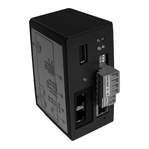
Viessmann Vitogate 200 Quick guide

Installation and service
instructions
for contractors
VIESMANN
Vitogate 200
Type EIB
Communication for heating systems via KNX/EIB systems
For applicability, see the last page
VITOGATE 200
5592 880 GB 6/2007 Please keep safe.

2
Please follow these safety instructions closely to prevent accidents and mate-
rial losses.
Safety instructions explained
Danger
This symbol warns against the
risk of injury.
!Please note
This symbol warns against the
risk of material losses and envi-
ronmental pollution.
Note
Details identified by the word "Note" con-
tain additional information.
Target group
These instructions are exclusively
designed for qualified personnel.
■ Work on gas equipment must only be
carried out by a qualified gas fitter.
■ Work on electrical equipment must
only be carried out by a qualified elec-
trician.
■ The system must be commissioned by
the system installer or a qualified per-
son authorised by the installer.
Regulations
Observe the following when working on
this system
■ all legal instructions regarding the pre-
vention of accidents,
■ all legal instructions regarding envi-
ronmental protection,
■ the Code of Practice of relevant trade
associations,
■ all current safety regulations as
defined by DIN, EN, DVGW, TRGI,
TRF, VDE and all locally applicable
standards,
■ Gas Safety (Installation & Use) Regu-
lations
– the appropriate Building Regulation
either the Building regulations, the
Building Regulation (Scotland),
Building Regulations (Northern Ire-
land),
– the Water Fittings Regulation or
Water Bylaws in Scotland,
– the current I.E.E. Wiring Regula-
tions.
If you smell gas
Danger
Escaping gas can lead to explo-
sions which may result in serious
injury.
■ Never smoke. Prevent naked
flames and sparks. Never
switch lights or electrical appli-
ances ON or OFF.
■ Close the gas shut-off valve.
■ Open windows and doors.
■ Remove all people from the
danger zone.
■ Notify your gas or electricity
supplier from outside the build-
ing.
■ Shut off the electricity supply to
the building from a safe place
(outside the building).
Safety instructions
Safety instructions
5592 880 GB

3
If you smell flue gas
Danger
Flue gas can lead to life-threat-
ening poisoning.
■ Shut down the heating system.
■ Ventilate the boiler room.
■ Close all doors leading to the
living space.
Working on the system
■ When using gas as fuel, also close the
main gas shut-off valve and safeguard
against unauthorised reopening.
■ Isolate the system from the power sup-
ply and check that it is no longer 'live',
e.g. by removing a separate fuse or by
means of a main isolator.
■ Safeguard the system against unau-
thorised reconnection.
!Please note
Electronic modules can be dam-
aged by electro-static dis-
charges.
Touch earthed objects, such as
heating or water pipes, to dis-
charge static loads.
Repair work
!Please note
Repairing components which ful-
fil a safety function can compro-
mise the safe operation of your
heating system.
Replace faulty components only
with original Viessmann spare
parts.
Ancillary components, spare and
wearing parts
!Please note
Spare and wearing parts which
have not been tested together
with the heating system can com-
promise its function. Installing
non-authorised components and
non-approved modifications/con-
version can compromise safety
and may invalidate our warranty.
For replacements, use only orig-
inal spare parts from Viessmann
or those which are approved by
Viessmann.
Safety instructions
Safety instructions (cont.)
5592 880 GB

4
Installation instructions
Preparing for installation................................................................................... 5
Installation sequence
Fitting the Vitogate 200, type EIB......................................................................... 6
Connection to the Vitotronic control unit............................................................... 6
Power supply........................................................................................................ 9
Service instructions
Commissioning
Display and control elements............................................................................... 12
Vitotronic control unit LON integration.................................................................. 12
EIB product database........................................................................................... 14
Communication objects and flags........................................................................ 15
Parameters in ETS............................................................................................... 18
Troubleshooting
BUS voltage/mains power failure......................................................................... 26
Characteristics after restoration of BUS voltage/mains power............................. 26
Connection fault between the Vitogate 200 and the EIB or LON system............. 26
Designs
Connection diagram............................................................................................. 27
Specification....................................................................................................... 28
Certificates
Declaration of conformity...................................................................................... 29
Keyword index.................................................................................................... 30
Index
Index
5592 880 GB

5
Product information
The Vitogate 200 type EIB gateway is
designed to hook up Vitotronic control
units with integral LON communication
module (accessory) to KNX/EIB sys-
tems.
The Vitogate 200, type EIB must be inte-
grated into the KNX/EIB system by an
authorised specialist.
Application
Communication is possible with the fol-
lowing Vitotronic control units:
Wall mounted gas boilers:
■ Vitotronic 100, type HC1
■ Vitotronic100, type HC2
■ Vitotronic 200, type HO1
■ Vitotronic 300-K, type MW2
Vitotronic 333, type MW2
Oil condensing boiler:
■ Vitotronic 200, type KW6
Medium and industrial/commercial boiler
systems:
■ Vitotronic 200-H, type HK1M
Vitotronic 050, type HK1M
■ Vitotronic 200-H, type HK1S, HK3S
Vitotronic 050, type HK1S, HK3S
■ Vitotronic 200-H, type HK1W, HK3W
Vitotronic 050, type HK1W, HK3W
■ Vitotronic 100, type GC1
■ Vitotronic 200, type GW1
■ Vitotronic 300, type GW2
■ Vitotronic 300-K, type MW1, MW1S
Vitotronic 333, type MW1, MW1S
Functions
The Vitogate 200, type EIB enables sys-
tem users to utilise the following func-
tions in conjunction with an EIB system:
■ Transfer of the operating states of the
heating system
■ Setting heating system parameters
■ Transfer of fault and error messages
■ Control of the flow temperature subject
to heat demand and in conjunction
with the Viessmann EIB module and
constant EIB control of individual room
temperature
Preparing for installation
5592 880 GB
Installation

6
The Vitogate 200, type EIB is suitable for
rail mounting (TS 35 to
EN 50 022 35 x 15 and 35 x 7.5) in control
panels and commercially available dis-
tribution boards.
Connection to the Vitotronic control unit
The Viessmann LON is designed for the "Line" BUS topology with a terminator at
both ends (accessories). For free wiring with a central terminator (BUS terminator),
please see the "Viessmann LON manual" at www.viessmann.de/lon.
The transfer distances for LON are subject to the electrical properties of the respec-
tive cabling. For this reason, only use the stated cable types. Use only one type of
cable within one LON.
Cable types (on site):
■ 2-core cable, CAT 5, screened
■ JY(St)Y 2 x 2 x 0.8 mm (telephone cable)
Observe the cabling requirements for the operation of the LON interface FTT 10A
(see www.echelon.com).
All Viessmann LON devices are connected via RJ45 plugs. The Viessmann LON
always requires cores "1" and "2" plus the screen. The cores are interchangeable.
The installation is therefore reverse polarity protected.
Note
When connecting appliances/devices and during wiring, observe the requirements of
protection class II, i.e. 8.0 mm air and creep path or maintain a 2.0 mm insulation
thickness against live parts.
Ensure a safe electrical separation for all on-site components (incl. PC/laptops) to
ensure conformity to EN 60 335 or IEC 65.
Installation sequence
Fitting the Vitogate 200, type EIB
5592 880 GB

7
Connection with LON cable
C
A A B
D
C
D
Routing distance ≤ 7 m
AVitotronic control unit
BVitogate 200, type EIB
CTerminator
DLON cable, 7 m long
Connection with LON cable and LON coupling
C
E
A A B
EDD D EE DD
C
D
Routing distance 7 to 21 m
AVitotronic control unit
BVitogate 200, type EIB
CTerminator
DLON cable, 7 m long
Max. 3 cables between 2 applian-
ces
ELON coupling
Installation sequence
Connection to the Vitotronic control unit (cont.)
5592 880 GB
Installation

8
Connection with on-site cable and LON plug
C
A A B
E
C
E
F
≤ 900 m
D D DD
Routing distance ≤ 900 m (with LON plug)
AVitotronic control unit
BVitogate 200, type EIB
CTerminator
DLON plug
EOn-site cable
FUp to 99 subscribers
Connection with LON cable, on-site cable and LON socket
≤ 900 m
F
C
D
C
D D D
E
F F F
E
A A GB
Routing distance ≤ 900 m (with LON sockets)
AVitotronic control unit
BVitogate 200, type EIB
CTerminator
DLON cable, 7 m long
EOn-site cable
FLON sockets
GUp to 99 subscribers
Installation sequence
Connection to the Vitotronic control unit (cont.)
5592 880 GB

9
Directives
Regulations
Make the power supply connection and
take all earthing measures (i.e. RCD cir-
cuit) in accordance with IEC 364, the
requirements of your local power supply
utility, VDE or national regulations.
Protect the power cable to the Vito-
gate 200, type EIB with a fuse with a
maximum rating of 16 A.
Main isolator requirements (if
required)
For combustion equipment to DIN VDE
0116, the main isolator installed on site
must comply with the requirements of
DIN VDE 0116 "section 6" [or local reg-
ulations].
Fit the main isolator outside the installa-
tion room. It must be able to isolate all
non-earthed conductors simultaneously
with at least 3 mm contact separation.
Power supply via the main isolator
When the heating system is switched off
via the main isolator, the Vitogate 200,
type EIB and the Vitotronic control unit
are also switched off.
No data is transferred to the EIB sys-
tem.
L1
PE
N
B
C
D
N
L
40
BN
BU
GNYE
E
A
F
L1 N
AVitogate 200, type EIB
BPower supply 230 V/50Hz
CFuse (max. 16 A)
DMain isolator, 2-pole, on site (if
installed)
EJunction box (on site)
FVitotronic control unit power supply
(plug fÖ)
Installation sequence
Power supply
5592 880 GB
Installation

10
1. Check whether the power cable to the
Vitotronic control unit has appropriate
fuse protection.
2. Connect the power cable on site
inside junction box E and at plug
fÖ.
Danger
Incorrect core termination can
cause severe injuries and
damage to the appliance.
Never interchange cores "L1"
and "N":
L1 brown
N blue
PE green/yellow
3. Insert plug fÖ into the Vitotronic con-
trol unit.
Colour coding to DIN IEC 60757
BN brown
BU blue
GNYE green/yellow
Power supply independent of the main isolator
When the heating system is switched off
via the main isolator, the Vitogate 200,
type EIB remains on, whilst the Vitotronic
control unit is switched off.
No data is transferred to the EIB sys-
tem.
L1
PE
N
B
C
40
D
AL1 N
F
N
L
E
BN
BU
GNYE
AVitogate 200, type EIB
BPower supply 230 V/50Hz
CFuse (max. 16 A)
DJunction box (on site)
EMain isolator, 2-pole, on site (if
installed)
Installation sequence
Power supply (cont.)
5592 880 GB

11
FVitrotronic control unit power supply
(plug fÖ)
1. Check whether the power cable to the
Vitotronic control unit has appropriate
fuse protection.
2. Connect the power cable on site
inside junction box D and at plug
fÖ.
Danger
Incorrect core termination can
cause severe injuries and
damage to the appliance.
Never interchange cores "L1"
and "N":
L1 brown
N blue
PE green/yellow
3. Insert plug fÖ into the Vitotronic con-
trol unit.
Installation sequence
Power supply (cont.)
5592 880 GB
Installation

12
Reset8
EIB ProgLON Service
A B
E
C D
F
AON indicator "8" (green)
BReset button (configuration is
retained)
CStatus display for the EIB system
BUS coupler (red)
DEIB programming key
for manual integration of the Vito-
gate 200, type EIB into an existing
EIB system
ELON service key
for manual integration of the Vito-
gate 200, type EIB into an existing
LON system
FLON display during LON subscriber
check (yellow-orange)
Vitotronic control unit LON integration
The LON communication module
(accessory) must be plugged into the
Vitotronic control unit.
Note
The data transfer via the LON system
can take several minutes.
Viessmann system number and subscriber number
Set LON system number, LON sub-
scriber number and further functions via
code 2.
Vitotronic control unit service
instructions and the following
table.
Note
Each number can only be allocated once
within the same LON.
Only one Vitotronic control unit per
system may be programmed as the fault
manager.
Commissioning
Display and control elements
5592 880 GB

13
Example: Single boiler system with control unit Vitotronic 300, type GW2
(V300GW2); heating circuit control unit Vitotronic 200-H, type HK3 (V050HK3)
installed downstream and Vitogate 200, type EIB
Vitotronic 300 Vitotronic 200-H Vitogate 200
LON LON
Subscriber no. 1
Code "77:1"
Subscriber no. 10
Code "77:10"
Subscriber no. 98
Control unit is fault man-
ager
Code "79:1"
Control unit is not fault
manager
Code "79:0"
Device is fault manager
Viessmann system num-
ber
Code "98:1"
Viessmann system num-
ber
Code "98:1"
—
LON subscriber fault mon-
itoring
Code "9C:20"
LON subscriber fault mon-
itoring
Code "9C:20"
—
Updating LON subscriber list
Preconditions:
■ All subscribers must be connected
■ The control unit must be programmed
as fault manager (code "79:1").
Press the following keys:
1. L + dsimultaneously for approx.
2 s.
The subscriber check has
been initiated.
2. eThe subscriber list is upda-
ted after approx. 2 min.
The subscriber check is
completed.
Carrying out subscriber check
In conjunction with LON.
Commissioning
Vitotronic control unit LON integration (cont.)
5592 880 GB
Service

14
Communication with the appliances connected to the fault manager in a system is
tested by means of the subscriber check.
Preconditions:
■ The control unit must be programmed
as fault manager (code "79:1").
■ The LON subscriber number must be
programmed in all control units (see
page 12).
■ The fault manager LON subscriber list
must be up to date (see page 13).
Press the following keys:
1. L + dsimultaneously for approx.
2 s.
The subscriber check has
been initiated.
User check
01 01:
AConsecutive number
in the subscriber list
BSubscriber number
2. a/bfor the required subscriber.
3. dCheck is active.
"Check" flashes until its
completion. The display
and all backlit keys for the
selected subscriber flash
for approx. 60 s.
4. "Check OK" is displayed during com-
munication between both devices.
"Check not OK" is displayed if there
is no communication between both
devices. Check the LON connection
and encoding.
5. Repeat points 2 and 3 to check further
subscribers.
6. L + dsimultaneously for approx.
1 s.
The subscriber check is
completed.
EIB product database
The EIB product database for the Vito-
gate 200, type EIB can be downloaded
from www.viessmann.de/vito-
gate-200-eib.
Download the EIB product database and
then import it into the EIB Tool software
(ETS). Only then can the parameters for
the communication objects be set for the
KNX/EIB system.
Commissioning
Vitotronic control unit LON integration (cont.)
5592 880 GB

15
The Vitogate 200, type EIB must be inte-
grated into the KNX/EIB system by an
authorised specialist; this is not part of
the standard delivery from Viessmann.
Characteristics after download
A full reset is triggered after each down-
load to the Gateway by means of the
ETS.
The configuration is retained.
Communication objects and flags
The Vitotronic control units connected
via LON provide a total of 81 data-
points.
From these datapoints, the Vitogate 200,
type EIB transmits up to 32 datapoints
plus an error bit and an error byte to the
EIB system. Each of these 34 datapoints
corresponds to a communication object
in the EIB system.
"Flags" are preset for each datapoint.
This preset determines whether a data-
point is read only or write enabled via the
Vitogate 200, type EIB. If the "write" flag
is deleted for a datapoint, then it can no
longer be written to via the EIB system,
although this would be possible via the
Vitogate 200, type EIB.
Datapoints are assigned to every
Vitotronic control unit. Subject to the
parameter settings, the associated data-
point list will be available in a pop-up
menu.
A list of every available datapoint can be
downloaded from www.viessmann.de/
vitogate-200-eib.
Communication objects (delivered condition)
0: Betriebsart EIS6 - A1: Betriebsart EIS6 (Operating mode EIS6 - A1: Operating
mode EIS6)
1: Betriebsart EIS6 - A1: Betriebsart EIS6
2: Betriebsart EIS6 - A1: Betriebsart EIS6
3: Betriebsart EIS6 - A1: Betriebsart EIS6
4: Betriebsart EIS6 - A1: Betriebsart EIS6
5: Betriebsart EIS6 - A1: Betriebsart EIS6
6: Betriebsart EIS6 - A1: Betriebsart EIS6
7: Betriebsart EIS6 - A1: Betriebsart EIS6
Commissioning
EIB product database (cont.)
5592 880 GB
Service

16
8: Betriebsart EIS6 - A1: Betriebsart EIS6
9: Betriebsart EIS6 - A1: Betriebsart EIS6
10: Betriebsart EIS6 - A1: Betriebsart EIS6
11: Betriebsart EIS6 - A1: Betriebsart EIS6
12: Betriebsart EIS6 - A1: Betriebsart EIS6
13: Betriebsart EIS6 - A1: Betriebsart EIS6
14: Betriebsart EIS6 - A1: Betriebsart EIS6
15: Betriebsart EIS6 - A1: Betriebsart EIS6
16: Betriebsart EIS6 - A1: Betriebsart EIS6
17: Betriebsart EIS6 - A1: Betriebsart EIS6
18: Betriebsart EIS6 - A1: Betriebsart EIS6
19: Betriebsart EIS6 - A1: Betriebsart EIS6
20: Betriebsart EIS6 - A1: Betriebsart EIS6
21: Betriebsart EIS6 - A1: Betriebsart EIS6
22: Betriebsart EIS6 - A1: Betriebsart EIS6
23: Betriebsart EIS6 - A1: Betriebsart EIS6
24: Betriebsart EIS6 - A1: Betriebsart EIS6
25: Betriebsart EIS6 - A1: Betriebsart EIS6
26: Betriebsart EIS6 - A1: Betriebsart EIS6
27: Betriebsart EIS6 - A1: Betriebsart EIS6
28: Betriebsart EIS6 - A1: Betriebsart EIS6
29: Betriebsart EIS6 - A1: Betriebsart EIS6
30: Betriebsart EIS6 - A1: Betriebsart EIS6
31: Betriebsart EIS6 - A1: Betriebsart EIS6
32: DP Fehlerbit - DP Fehlerbit (DP error bit - DP error bit)
33: DP Fehlerbyte - DP Fehlerbyte (DP error byte - DP error byte)
Commissioning
Communication objects and flags (cont.)
5592 880 GB

17
Flags for read only datapoints (delivered condition)
Flags for write only datapoints (delivered condition)
Explanation of flags
Flag Explanation
Kommunikation (Com-
munication)
Authority for communication with EIB system (corresponds
to a main switch)
Lesen (Read) Read request via EIB system, if the group address in this
communication object stands in first position.
Schreiben (Write) Authority to write via the EIB system
Commissioning
Communication objects and flags (cont.)
5592 880 GB
Service

18
Flag Explanation
Übertragen (Transfer) Authority to transfer the group address via the EIB sys-
tem
Aktualisieren (Update) For automatic updates following a power failure
Parameters in ETS
With the Vitogate 200, type EIB, up to 32
communication objects can be pro-
cessed by the Vitotronic control units in
the EIB system connected via LON.
The heating system fault messages are
transferred in the form of an error bit and/
or an error byte.
Commissioning
Communication objects and flags (cont.)
5592 880 GB

19
Datapoints
Example with ETS3
The following parameters can be set for
each communication object:
1. Regelung (Control unit)
2. Anlagen Nummer (System number)
3. Teilnehmer-Nummer (Subscriber
number)
4. Dienst (Service)
5. Gruppe (Group)
6. Datenpunkt (Data point)
7. Zykluszeit (Cycle time)
8. max Abweichung gegenüber zuletzt
gesendeten Wert (max deviation from
the value transmitted last)
1. Regelung
Menu for the selection of the Vitotronic
control unit to be assigned to the corre-
sponding communication object.
Commissioning
Parameters in ETS (cont.)
5592 880 GB
Service

20
Menu selection Vitotronic control unit
V050HK1W Vitotronic 050, type HK1W, HK1S
Vitotronic 200-H, type HK1W, HK1S
V050HK1M Vitotronic 050, type HK1M
Vitotronic 200-H, type HK1M
V050HK3 Vitotronic 050, type HK3W, HK3S
Vitotronic 200-H, type HK3W, HK3S
V100GC1 Vitotronic 100, type GC1
V200GW1 Vitotronic 200, type GW1
V300GW2 Vitotronic 300, type GW2
V333MW1S Vitotronic 333, type MW1, MW1S
Vitotronic 300-K, type MW1, MW1S
V333MW2 Vitotronic 333, type MW2
Vitotronic 300-K, type MW2
VScotHC Vitotronic 100, type HC1, HC2
VScotHO1 Vitotronic 200, type HO1
VPlusHC Vitotronic 100, type HC1, HC2
VPlusHO1 Vitotronic 200, type HO1
Vitotronic 200, type KW6
VDensHC Vitotronic 100, type HC1, HC2
VPendHC Vitotronic 100, type HC1, HC2
VDensHO1 Vitotronic 200, type HO1
VPendHO1 Vitotronic 200, type HO1
2. Anlagen Nummer
Menu for the selection of the Viessmann
system number to be assigned to the
corresponding communication object.
■ Menu selection: 1 to 5
If several systems are connected to a
LON, a number is assigned to each sys-
tem.
Up to 5 systems are possible. A system
may comprise up to 4 boilers, up to 32
heating circuit control units and 1 cas-
cade control unit.
Note
The Viessmann system number must
also be programmed into the Vitotronic
control unit selected under "Regelung"
(for coding, see page 13).
3. Teilnehmer-Nummer
Menu for the selection of the subscriber
number to be assigned to the corre-
sponding communication object.
■ Menu selection: 1 to 97
If several Vitotronic control units are inte-
grated into the LON, a number will be
assigned to each one of them.
A total of 97 Vitotronic control units can
be integrated into a single LON.
Commissioning
Parameters in ETS (cont.)
5592 880 GB
Other manuals for Vitogate 200
1
This manual suits for next models
1
Table of contents
Other Viessmann Gateway manuals

Viessmann
Viessmann Vitogate 300 Quick guide

Viessmann
Viessmann WAGO BACnet/IP Quick guide

Viessmann
Viessmann Vitogate 300 Operator's manual

Viessmann
Viessmann WAGO MB/TCP gateway Quick guide

Viessmann
Viessmann WAGO 750-8212/000-100 Operating instructions

Viessmann
Viessmann Vitogate 300 Operating instructions
Viessmann
Viessmann WAGO MB/TCP gateway Operating instructions

Viessmann
Viessmann WAGO KNX/TP gateway Operating instructions