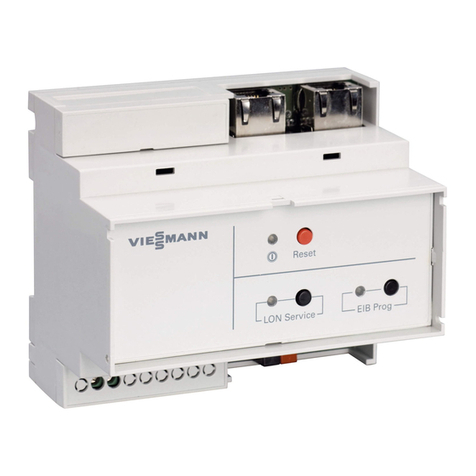
Viessmann WAGO KNX/TP gateway Operating instructions

Installation and service instructions
for contractors
VIESMANN
WAGO KNX/TP gateway
BMS communication with heating systems via KNX/EIB
WAGO KNX/TP gateway
5853847 GB 7/2019 Please keep safe.

2
Please follow these safety instruc-
tions closely to prevent accidents
and material losses.
Safety instructions explained
Danger
This symbol warns against the risk
of injury.
!Please note
This symbol warns against the risk
of material losses and environmen-
tal pollution.
Target group
These instructions are exclusively inten-
ded for qualified contractors.
■Work on electrical equipment may only
be carried out by a qualified electrician.
■The system must be commissioned by
the system installer or a qualified per-
son authorised by the installer.
■Training is required for handling the
components of the WAGO-I/O-System
750. The training includes the design
notes – see also the manual at
www.wago.de (search text: "Projek-
tierungshinweise").
Regulations to be observed
■National installation regulations
■Statutory regulations for the prevention
of accidents
■Statutory regulations for environmental
protection
■Codes of practice of the relevant trade
associations
■Relevant country-specific safety regu-
lations
Safety instructions for working on the system
Working on the system
■Isolate the system from the power sup-
ply (e.g. by removing the separate fuse
or by means of a mains isolator) and
check that it is no longer live.
■Safeguard the system against recon-
nection.
Danger
Hot surfaces can cause burns.
■Before maintenance and service
work, switch off the appliance and
let it cool down.
■Never touch hot surfaces on the
boiler, burner, flue system or pipe-
work.
Safety instructions
Safety instructions
5853847

3
!Please note
Electronic assemblies can be dam-
aged by electrostatic discharge.
Prior to commencing any work,
touch earthed objects such as heat-
ing or water pipes to discharge
static loads.
Repair work
!Please note
Repairing components that fulfil a
safety function can compromise the
safe operation of the system.
Replace faulty components only
with genuine Viessmann spare
parts.
Auxiliary components, spare and
wearing parts
!Please note
Spare and wearing parts that have
not been tested together with the
system can compromise its func-
tion. Installing non-authorised com-
ponents and making non-approved
modifications or conversions can
compromise safety and may invalid-
ate our warranty.
For replacements, use only original
spare parts supplied or approved by
Viessmann.
Safety instructions for operating the system
If you smell flue gas
Danger
Flue gas can lead to life threatening
poisoning.
■Shut down the heating system.
■Ventilate the installation site.
■Close the doors to living spaces to
prevent flue gases from spread-
ing.
What to do if water escapes from the
appliance
Danger
If water escapes from the appliance
there is a risk of electric shock.
Switch off the heating system at the
external isolator (e.g. fuse box,
domestic distribution board).
Flue systems and combustion air
Ensure that flue systems are clear and
cannot be sealed, for instance due to
accumulation of condensate or other
external causes. Ensure an adequate
supply of combustion air.
Instruct system users that subsequent
modifications to the building characteris-
tics are not permissible (e.g. cable/pipe-
work routing, cladding or partitions).
Danger
Leaking or blocked flue systems, or
an inadequate supply of combus-
tion air can cause life threatening
poisoning from carbon monoxide in
the flue gas.
Ensure the flue system is in good
working order. Vents for supplying
combustion air must be non-seala-
ble.
Extractors
Operating appliances that extract air to
the outside (extractor hoods, extractors,
air conditioning units, etc.) can create
negative pressure. If the boiler is oper-
ated at the same time, this can lead to a
reverse flow of flue gas.
Safety instructions
Safety instructions (cont.)
5853847

4
Danger
The simultaneous operation of the
boiler and appliances that extract
air to the outside can result in life
threatening poisoning due to a
reverse flow of flue gas.
Fit an interlock circuit or take suita-
ble steps to ensure an adequate
supply of combustion air.
Safety instructions
Safety instructions (cont.)
5853847

5
1. Information Disposal of packaging ............................................................................ 6
Symbols ................................................................................................. 6
Intended use .......................................................................................... 6
Product information ................................................................................ 7
■Functions ............................................................................................ 7
Spare parts lists ..................................................................................... 7
2. Preparing for installation ................................................................................................................ 8
3. Installation sequence Process overview ................................................................................... 9
Installing the gateway and power supply unit ........................................ 9
■Installing the gateway ......................................................................... 11
■Installing the power supply unit .......................................................... 12
Overview of connections ........................................................................ 13
■Connecting and releasing cores ......................................................... 14
■Operating elements ............................................................................ 14
■Display elements ................................................................................ 15
■Power supply unit ............................................................................... 16
Establishing the CAN bus connection .................................................... 16
Connecting the plug-in attachment ........................................................ 17
■If the gateway is at the beginning or end of the CAN bus: ................. 17
■If the gateway is not at the beginning or end of the CAN bus: ........... 17
Establishing a connection to the KNX .................................................... 18
Power supply ......................................................................................... 18
■General information ............................................................................ 18
■Connecting cores in the power supply unit ......................................... 19
■Power supply via the mains isolator ................................................... 21
■Power supply independent of the mains isolator ................................ 22
4. Commissioning and
adjustment
Commissioning the gateway .................................................................. 23
5. Specification ................................................................................................................ 29
6. Appendix Final decommissioning and disposal ..................................................... 31
7. Certificates Declaration of conformity ....................................................................... 32
8. Keyword index ................................................................................................................ 33
Index
Index
5853847

6
Please dispose of packaging waste in line with statu-
tory regulations.
Symbols
Symbol Meaning
Reference to other document containing
further information
1.
Step in a diagram:
The numbers correspond to the order in
which the steps are carried out.
Warning of material losses and environ-
mental pollution
Live electrical area
Pay particular attention.
■Component must audibly click into place.
or
■Acoustic signal
■Fit new component.
or
■In conjunction with a tool: Clean the sur-
face.
Dispose of component correctly.
Dispose of component at a suitable collec-
tion point. Do not dispose of component in
domestic waste.
Intended use
The gateway is only intended to be installed and oper-
ated in conjunction with Viessmann control units, with
due attention paid to the associated installation, serv-
ice and operating instructions. The gateway may only
be used in systems with supported Viessmann heat
and power generators.
The gateway can only be used with the user and com-
munication interfaces defined in the product documen-
tation for the following purposes:
■To monitor systems
■To operate systems
■To optimise systems
With regard to the communication interfaces, ensure
on site that the system requirements specified in the
product documentation are met at all times for every
transfer medium employed. Only use the specified
components for the power supply (e.g. power supply
units).
Intended use presupposes that a fixed installation in
conjunction with permissible, system-specific compo-
nents has been carried out.
Information
Disposal of packaging
5853847
Service

7
Commercial or industrial use for a purpose other than
the monitoring, operation and optimisation of suppor-
ted, approved systems shall be deemed inappropriate.
Incorrect usage or operation of the appliance (e.g. the
appliance being opened by the system user) is prohibi-
ted and will result in an exclusion of liability. Incorrect
usage also occurs if the components in the Viessmann
system are modified from their intended function.
Product information
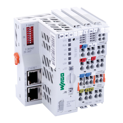
The WAGO KNX/TP gateway is used to connect
Viessmann control units to KNX/EIB systems. For sup-
ported devices and other valid product documentation,
see www.automation-gateway.info
Functions
The gateway enables system users to utilise the fol-
lowing functions in conjunction with a KNX/EIB system:
■Transferring heating system operating states
■Setting heating system parameters
■Relaying fault and maintenance messages
Spare parts lists
Information about spare parts can be found on the
Viessmann spare parts app.
Information
Intended use (cont.)
5853847
Service

8
System overview
100 - 240 V~ 24 V CAN bus
LAN KNX
A
B
C
DE
F
Fig. 1
AViessmann heat generator
BBuilding management system
CTerminator 120 Ω
DGateway
EPower supply unit
FLaptop with web browser and WAGO Web-Visu
Preparing for installation
5853847
Installation

9
Step Responsibility Page
1 Install the gateway and power supply unit. Contractor 9
2 Establish the CAN bus connection to the control unit. Contractor 16
3 Use a terminator. Contractor 17
4 Establish the connection to the KNX. IT expert/system integrator 18
5 Power supply Electrician 18
6 Commission the gateway. IT expert/system integrator 23
Installing the gateway and power supply unit
!Please note
Incorrect ambient conditions and installation
locations may impair data transfer and cause
damage to the device.
The gateway, together with its components, con-
stitutes an open device with IP 20 protection rat-
ing. It may only be installed in enclosures, cabi-
nets or in electrical plant rooms.
Ambient conditions during operation
■Permissible ambient temperature: 0 to 40 °C
■Permissible relative humidity:
–At 0 to 39 °C: Up to 95 %
–At 40 °C: Up to 50 %
■No direct sunlight
!Please note
Operation by unauthorised persons may result
in damage to the device.
Access to the gateway must only be possible for
authorised specialists with a key or tool.
Requirements for the enclosure
Material Sheet steel Plastic
Min. dimensions
(width x height x depth)
200 x 200 x 120 mm 278 x 278 x 130 mm
Protective conductor Connect the enclosure to the protec-
tive conductor.
Connect the top-hat rail to the protec-
tive conductor via a protective conduc-
tor terminal.
Flammability class —Min. flammability class V-1 according
to EN 62368-1 or EN 60950-1
Earthing Enclosure and top-hat rail:
Depending on phase conductor
cross-section with min. 2.5 mm2
Top-hat rail:
Depending on phase conductor cross-
section with min. 2.5 mm2
IP rating ■Installed at a height of up to 1.60 m: IP 20D
■Installed at a height of 1.61 m or higher: IP 20B
Top-hat rail mounting ■TS 35 to EN 50022
■Length: Min. 190 mm
Installation sequence
Process overview
5853847
Installation

10
Overview of connecting cables
Connecting cables Length
Standard delivery:
Cable cores between gateway and power supply unit 0.52 m
Accessories:
CAN bus cable 7 m
On site:
Recommended power cable 3-core:
■H05VV-F3G 1.5 mm2
■H05RN-F3G 1.5 mm2
■The gateway and power supply unit are suitable for
mounting on top-hat rails in control panels:
TS 35 to EN 50 022: 35 x 15 and 35 x 7.5.
■With sub-distribution boards, mount both devices on
a lower top-hat rail.
■Arrange the components on the top-hat rail as shown
in the following figure.
Fig. 2
Installation sequence
Installing the gateway and power supply unit (cont.)
5853847
Installation

11
Installing the gateway
2.
1.
3.
Fig. 3
4. Affix the supplied type plate (self-adhesive) to the
system in a visible location.
Installation sequence
Installing the gateway and power supply unit (cont.)
5853847
Installation

12
Installing the power supply unit
1.
2.
4.
3.
Fig. 4
Installation sequence
Installing the gateway and power supply unit (cont.)
5853847
Installation

13
+ +
‒ ‒
SYS
0V
RST
RUN
l/0
MS
NS
USR
24V
+‒
A
W
L
G
CB D FE
S
M
PRTU
V
X
H
K
N
O
Q
Fig. 5
AAddress selector
BLED status indicators
CReset button RST
DStatus LED for supply voltage
EStatus LED for CAN bus interface
FStatus LED for KNX/EIP/TP interface
GPlug-in attachment with terminator
HCAN high, for looping through the CAN bus
KCAN low, for looping through the CAN bus
LProgramming button connection
MKNX bus "+"
NCAN low
OCAN high
PKNX bus "–"
QCAN bus shield
RShield
S24 V supply voltage connection
TDo not open!
UOperating mode switch
VService interface: LAN port for connection to PC/
laptop
WMemory card slot
XFixing for mounting on the top-hat rail
Installation sequence
Overview of connections
5853847
Installation

14
Connecting and releasing cores
1.
2.
3.
Fig. 6
Operating elements
Address selector
1 2 3 4 5 6 7 8
ON
Fig. 7
Factory setting: Do not adjust!
Operating mode switch
RESET STOP RUN
Fig. 8
RUN Standard mode
Factory setting: Do not adjust!
STOP Do not adjust!
RESET Do not adjust!
Installation sequence
Overview of connections (cont.)
5853847
Installation

15
Reset button
RST
2 3 4 5 6 7 8
ON
1
Fig. 9
Memory card slot
RESET STOP RUN
µSD
Fig. 10
Display elements
Designation Status Meaning Measure
User LED "USR" Green The connection to the heat gen-
erator is active.
—
Red The CAN bus interface has the
status "Bus Off": Short circuit or
other serious fault
■Check CAN bus connection:
Plug, cable, terminator
■Check whether heat generator
is switched on.
■Check module setup.
■Check address selector. If nec-
essary, restore the factory set-
tings as shown in the figure on
page 14.
■If the fault cannot be rectified,
contact Viessmann Werke
Technical Service.
Other Fault Contact Viessmann Werke Tech-
nical Service.
Installation sequence
Overview of connections (cont.)
5853847
Installation

16
Power supply unit
A B
L N PE + + - -
Fig. 11
A INPUT 100 to 240 V/50 Hz/60 Hz
B OUTPUT 24 V
1.3 A
Establishing the CAN bus connection
■The Viessmann CAN bus is designed for "line" bus
topology with a terminator at both ends (accesso-
ries).
■With CAN bus, the transmission quality and the
cable lengths depend on the electrical properties of
the cable:
–Only use cable types listed in the following table.
–Only use one cable type within a CAN bus.
Recommended cable type (on site):
CAN bus cable In line with ISO 11898-2, twisted pair cable, shielded
■Cable cross-section 0.34 to 0.6 mm2
■Characteristic impedance 95 to 140 Ω
■Max. length 200 m
Alternative cable types (on site):
CAN bus cable 2-core, CAT5, shielded
■Max. length 50 m
CAN bus cable 2-core, CAT7, shielded
■Max. length 200 m
1. To connect the CAN bus cable to the gateway: See
page 13.
Installation sequence
Overview of connections (cont.)
5853847
Installation

17
2. Connect the CAN bus cable to connection lA of
the heat generator control unit. The plug is part of
the standard delivery of the gateway.
Installation and service instructions for the
control unit of the heat generator
3. Connect the shielding of the CAN bus cable to the
gateway: See page 13.
Connecting the plug-in attachment
The plug-in attachment (standard delivery) must be
plugged in.
Do not connect the plug-in attachment until the CAN
bus cable has been connected.
If the gateway is at the beginning or end of the CAN bus:
A
Fig. 12
APlug-in attachment with terminator (standard deliv-
ery)
If the gateway is not at the beginning or end of the CAN bus:
Plug in the plug-in attachment without the terminator. Use the plug-in attachment for looping through the
CAN bus.
Installation sequence
Establishing the CAN bus connection (cont.)
5853847
Installation

18
A
4.
2.
B
1.
2x
3.
2x
Fig. 13
APlug-in attachment (standard delivery)
BTerminator
Establishing a connection to the KNX
The connection to the required network must be estab-
lished by the system integrator. For connections, see
page 13.
Power supply
General information
Danger
Incorrect wiring can lead to serious injury from
electrical current and result in appliance dam-
age.
■Route extra low voltage (ELV) leads < 42 V
separately from cables > 42 V/230 V~.
■Strip as little of the insulation as possible,
directly before the terminals. Bundle cables
close to the corresponding terminals.
■Secure cables with cable ties.
The gateway is connected to the public low voltage
network via the power supply unit (standard delivery).
Mains type TN-S/TT: Separate neutral and protective
conductors in the entire system.
The mains voltage should be single-phase, 100 to
240 V, 50/60 Hz and must be within the voltage range
limits defined in the VDE regulations.
Recommended power cable: 3-core
■H05VV-F3G 1.5 mm2
■H05RN-F3G 1.5 mm2
The connection versions for the power supply descri-
bed below have an effect on the characteristics of the
gateway:
■Characteristics in the event of power failure
■Characteristics during heating system shutdown
■Characteristics during gateway shutdown
Installation sequence
Connecting the plug-in attachment (cont.)
5853847
Installation

19
The connection version must be selected subject to
the heating system and the required monitoring func-
tion. The recommended connection version is the
"power supply via the mains isolator".
Regulations
Connect the power supply and implement all safety
measures (e.g. RCD circuit) in accordance with
IEC 364, the connection requirements of your local
power supply utility, and VDE or national regulations.
Protect the power cable to the gateway power supply
unit with a maximum fuse rating of 16 A across all
poles.
Isolators for non-earthed conductors
■Install an isolator in the power cable to provide
omnipolar separation from the mains for all active
conductors, corresponding to overvoltage cate-
gory III (3 mm) for complete isolation. This isolator
must be fitted in the permanent electrical installation
in line with installation requirements, e.g. mains iso-
lator or upstream circuit breaker.
■We additionally recommend installing an AC/DC-
sensitive RCD (RCD class B ) for DC (fault)
currents that can occur with energy efficient equip-
ment.
Connecting cores in the power supply unit
3.
1.
2.
Fig. 14
Installation sequence
Power supply (cont.)
5853847
Installation

20
+ +
‒ ‒
‒
+‒
+
PE
N
L
SYS
0V
RST
RUN
l/0
MS
NS
USR
24V
Fig. 15
Installation sequence
Power supply (cont.)
5853847
Installation
Table of contents
Other Viessmann Gateway manuals

Viessmann
Viessmann Vitogate 300 Operator's manual

Viessmann
Viessmann Vitogate 200 Quick guide

Viessmann
Viessmann Vitogate 300 Quick guide

Viessmann
Viessmann Vitogate 300 Operating instructions

Viessmann
Viessmann WAGO 750-8212/000-100 Operating instructions

Viessmann
Viessmann WAGO MB/TCP gateway Quick guide

Viessmann
Viessmann WAGO BACnet/IP Quick guide

Viessmann
Viessmann WAGO MB/TCP gateway Operating instructions