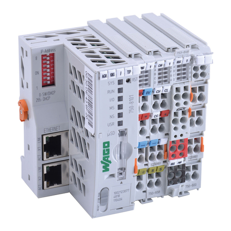
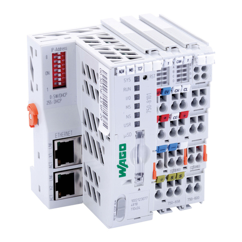
Viessmann WAGO MB/TCP gateway Quick guide

Please file in Service Binder
5472 800 - 02 04/2022
WAGO MB/TCP GATEWAY
WAGO MB/RTU GATEWAY
Installation and
Service Instructions
for use by heating contractor
BMS communication with heating systems via Modbus
WAGO MB/TCP GATEWAY
WAGO MB/RTU GATEWAY
Product may not be exactly as shown
Read and save these instructions
for future reference.
IMPORTANT
Read and save these instructions
for future reference.
Product may not be exactly as shown
IMPORTANT

2
5472 800 - 02
WAGO Gateway Installation and Service
Safety, Installation and Warranty Requirements
Please ensure that these instructions are read and understood before commencing installation. Failure to comply with
the instructions listed below and details printed in this manual can cause product/property damage, severe personal
injury, and/or loss of life. Ensure all requirements below are understood and fulfilled (including detailed information
found in manual subsections).
Product documentation
Read all applicable documentation before commencing
installation. Store documentation near boiler in a
readily accessible location for reference in the future
by service personnel.
For a listing of applicable literature,
please see section entitled “Important
Regulatory and Safety Requirements”.
Licensed professional heating contractor
The installation, adjustment, service and maintenance
of this equipment must be performed by a licensed
professional heating contractor.
Please see section entitled Safety and
“Important Regulatory and Installation
Requirements”.
Advice to owner
Once the installation work is complete, the heating
contractor must familiarize the system operator/
ultimate owner with all equipment, as well as safety
precautions/requirements, shutdown procedure, and
the need for professional service annually before the
heating season begins.
Safety
Warranty
Information contained in this and
related product documentation must
be read and followed. Failure to do
so renders the warranty null and void.
2
Safety, Installation and Warranty Requirements

3
5472 800 - 02
WAGO Gateway Installation and Service
3
Safety
General Information
Installation
Specifications
Additional Information
Safety, Installation and Warranty Requirements..............2
Product documentation ..........................................2
Licensed professional heating contractor ..................2
Advice to owner ...................................................2
Warranty..............................................................2
Important Regulatory and Installation Requirements ....... 4
Approvals.............................................................4
Codes..................................................................4
Working on the equipment......................................4
Power supply .......................................................4
About these Installation Instructions .............................4
Intended Use ............................................................... 5
Product Information...................................................5
Spare Parts Lists ........................................................5
Mounting the Gateway ...............................................6
Preparing for Installation..............................................7
Process Overview.......................................................8
Installing the Module ..................................................8
Connections and Operating Elements ............................9
Connecting and Releasing Cores.................................12
Establishing the CAN Bus Connection .........................13
Connecting the Plug-in Attachment ........................ 15
Establishing the Connections to the Modbus/TCP or
Modbus/RTU ...........................................................16
Connecting the Gateway to the Power Supply Unit.......16
Power Supply ..........................................................17
Commissioning the Gateway......................................18
Dismounting the Power Supply Unit............................18
Dismounting the Gateway.........................................19
Gateway .................................................................20
Power Supply ..........................................................22
Final Decommissioning and Disposal ...........................23
Page
Table of Contents
Page

4
5472 800 - 02
WAGO Gateway Installation and Service
General Information
Important Regulatory and Installation Requirements
Approvals
Viessmann boilers, burners and controls are approved for
sale in North America by CSA International.
Codes
The installation of this unit shall be in accordance with
local codes. In the absence of local codes, use:
- CSA C22.1 Part 1 and/or local codes in Canada
- National Electrical Code ANSI/NFPA 70 in the U.S.
Always use latest editions of codes.
The heating contractor must comply with the Standard
for Controls and Safety Devices for Automatically Fired
Boilers, ANSI/ASME CSD-1 where required by the
authority having jurisdiction.
Working on the equipment
The installation, adjustment, service, and maintenance
of this product must be done by a licensed professional
heating contractor who is qualified and experienced in the
installation, service, and maintenance of hot water boilers.
There are no user serviceable parts on the boiler, burner,
or control.
Power supply
Install power supply in accordance with the regulations
of the authorities having jurisdiction or, in absence of
such requirements, in accordance with National Codes.
Viessmann recommends the installation of a disconnect
switch to the 120V power supply outside of the boiler
room.
Ensure main power supply to equipment, the heating
system, and all external controls have been deactivated.
Close main oil or gas supply valve. Take precautions in
both instances to avoid accidental activation of power
during service work.
Please carefully read this manual prior to attempting
installation. Any warranty is null and void if these
instructions are not followed.
For information regarding other Viessmann System
Technology componentry, please reference
documentation of the respective product.
We offer frequent installation and service seminars
to familiarize our partners with our products. Please
inquire.
The completeness and functionality of field supplied
electrical controls and components must be verified
by the heating contractor. These include low water
cut-offs, flow switches (if used), staging controls,
pumps, motorized valves, air vents, thermostats, etc.
WARNING
Turn off electric power supply before
servicing. Contact with live electric
components can cause shock or loss
of life.
About these Installation Instructions
Take note of all symbols and notations intended to draw attention to potential hazards or important
product information.
CAUTION
Cautions draw your attention to the presence of potential
hazards or important product information.
WARNING
Warnings draw your attention to the presence of potential
hazards or important product information.
IMPORTANT
Indicates an imminently hazardous situation which,
if not avoided, could result in death, serious injury or
substantial product/property damage.
Indicates an imminently hazardous situation which,
if not avoided, may result in minor injury or product /
property damage.
Helpful hints for installation, operation or maintenance
which pertain to the product.
This symbol indicates to note additional information
This symbol indicates that other instructions must be
referenced.
5
5472 800 - 02
WAGO Gateway Installation and Service Installation
Intended Use
The WAGO MB/TCP gateway and the WAGO MB/RTU
gateway are used to connect Viessmann control units
to Modbus systems. For supported devices and other
valid product documentation, see;
www automationgateway.info
Functions
The gateway enables system users to utilise the following
functions in conjunction with a Modbus system:
H Transferring heating system operating states
H Setting heating system parameters
HRelaying fault and maintenance messages
Intended use
The gateway is only intended to be installed and operated
in conjunction with Viessmann control units, with due
attention paid to the associated installation, service and
operating instructions. The gateway may only be used
in systems with supported Viessmann heat and power
generators.
The gateway can only be used with the user and
communication interfaces defined in the product
documentation for the following purposes:
H To monitor systems
H To operate systems
H To optimize systems
With regard to the communication interfaces, ensure
on site that the system requirements specified in the
product documentation are met at all times for every
transfer medium employed. Only use the specified
components for the power supply (e.g. power supply units).
Intended use presupposes that a fixed installation in
conjunction with permissible, system-specific components
has been carried out.
Commercial or industrial use for a purpose other than
the monitoring, operation and optimization of supported,
approved systems shall be deemed inappropriate.
Incorrect usage or operation of the appliance (e.g. the
appliance being opened by the system user) is prohibited
and will result in an exclusion of liability. Incorrect usage
also occurs if the components in the Viessmann system
are modified from their intended function.
Product Information
Spare Parts Lists
Information about spare parts can be found at
www.viessmann.com/etapp or in the Viessmann
spare part app.

6
5472 800 - 02
WAGO Gateway Installation and Service
Mounting the Gateway
Installation
1. Loosen the retaining screws from the extension kit
enclosure (do not remove).
2. Remove cover and set aside.
3. Mount the extension module enclosure to the wall
using the appropriate hardware.

7
5472 800 - 02
WAGO Gateway Installation and Service Installation
Legend
A Viessmann boiler
B Building management system
C Terminator 120
D Gateway
E Power supply unit
F Laptop with web browser and WAGO Web-Visu
G Module enclosure
WAGO MB/TCP gateway system overview
WAGO MB/RTU gateway system overview
Preparing for Installation

8
5472 800 - 02
WAGO Gateway Installation and Service
Installation
Process Overview
Installing the Module
Incorrect ambient conditions and installation locations may
impair data transfer and cause damage to the gateway.
Ambient conditions during operation
HPermissible ambient temperature: 32 to 104°F
(0 to 40°C)
HPermissible relative humidity:
– 32 to 104°F (0 to 39°C): ≤95%
– ≥104°F (≥40°C): ≤50%
HNo direct sunlight
Operation by unauthorized persons may result in damage
to the system. Access to the gateway must only be
possible for authorized specialists.
IMPORTANT
IMPORTANT
Step Responsibility Page
1 Establish the CAN bus connection. Contractor 13
2 Connect the plug-in attachment. Contractor 15
3 Establish the connection to the Modbus. IT expert/system integrator 16
4 Power supply Electrician 17
5 Commission the gateway. IT expert/system integrator 18
Overview of connecting cables
Connecting cables Length
Accessories:
CAN bus cable 23 ft. (7 m)
Installation

9
5472 800 - 02
WAGO Gateway Installation and Service Installation
Connections and Operating Elements
Legend
BLED status indicators
CReset button RST
DStatus LED for supply voltage
EStatus LED for CAN bus interface
FPlug-in attachment with terminator: See page 16
GCAN low, for looping through the CAN bus
HCAN high, for looping through the CAN bus
KCAN bus shield
L24VDC supply voltage connection
WAGO MB/TCP gateway
MDo not open!
NOperating mode switch
RUN Standard mode
Factory setting: Do not adjust!
STOP Only for update process; see WAGO
commissioning manual.
RESET Do not adjust!
OService interface: LAN connection to PC/laptop or
Modbus/TCP connection
PMemory card slot

10
5472 800 - 02
WAGO Gateway Installation and Service
Connections and Operating Elements (continued)
Installation
Legend
A Connection for PROFIBUS field bus plug for Mod-bus /
RTU building management system
BLED status indicators
CReset button RST
DStatus LED for supply voltage
EStatus LED for CAN bus interface
FStatus LED for Modbus/RTU interface
GPlug-in attachment with terminator: See page 16
HCAN high, for looping through the CAN bus
KCAN low, for looping through the CAN bus
WAGO MB/RTU gateway
PEarth
QModbus shield
RCAN bus shield
S24VDC supply voltage connection
TDo not open!
UOperating mode switch
RUN Standard mode
Factory setting: Do not adjust!
STOP Do not adjust!
RESET Do not adjust!
VService interface: LAN port for connection to PC/laptop
WMemory card slot

11
5472 800 - 02
WAGO Gateway Installation and Service Installation
Connections and Operating Elements (continued)
LED indicators
LED Status Meaning Measure
User LED UI Green The connection to the boiler is active. --
Red The CAN bus interface has the status
“Bus Off”: Short circuit or other serious
fault
HCheck CAN bus connection:
Plug, cable, terminator
HCheck whether boiler is switched on.
HCheck installation and connections of
gateway and power supply unit.
HCheck address selector. If necessary,
restore the factory settings as shown
in the diagram on page 10.
HIf the fault cannot be rectified, contact
Viessmann Technical Service.
Other Fault Contact Viessmann Technical Service.
Power supply unit
Legend
A INPUT 120VAC 60 Hz
BOUTPUT 24VDC, 1.3A
Legend
A PROFIBUS connector
BWAGO MB/RTU Gateway
Installing the PROFIBUS connector

12
5472 800 - 02
WAGO Gateway Installation and Service
Connections
Connecting and Releasing Cores
Installation
WAGO MB/TCP gateway
Power supply unit
1. Insert a small flat head screwdriver into the opening
direcly above the wire..
2. Tilt the handle of the screwdriver up.
3. Pull the wire straight out.
1. Using a small screwdriver push in the orange button
directly above the wire.
2. Pull the wire straight out.

13
5472 800 - 02
WAGO Gateway Installation and Service
Establishing the CAN Bus Connection
Installation
HThe Viessmann CAN bus is designed for “line” bus
topology with a terminator at both ends (accessories).
HWith CAN bus, the transmission quality and the cable
lengths depend on the electrical properties of the cable:
– Only use cable types listed in the following table.
– Only use one cable type within a CAN bus.
Recommended cable type (on site):
CAN bus cable In line with ISO 11898-2, twisted pair cable, shielded
HCable cross-section 0.34 to 0.6 mm2 (22 to 18 AWG)
HCharacteristic impedance 95 to 140 Ω
HMax. length 650 ft. (200 m)
Alternative cable types (on site):
CAN bus cable
HMax. length
2-core, CAT5, shielded
165 ft. (50 m)
CAN bus cable
HMax. length
2-core, CAT7, shielded
650 ft. (200 m)

14
5472 800 - 02
WAGO Gateway Installation and Service
Establishing the CAN Bus Connection (continued)
Installation
WAGO MB/TCP gateway
Legend
A CAN bus shield
BCable for lA for controlling the boiler
(standard delivery of the gateway)
Installation and service instructions for boiler
control unit

15
5472 800 - 02
WAGO Gateway Installation and Service
Connecting the Plug-in Attachment
Installation
WAGO MB/TCP/RTU gateway
The plug-in attachment (pre-installed) must be
plugged in.
Do not connect the plug-in attachment until the CAN
bus cable has been connected.
If the gateway is at the beginning or end of the CAN bus:
Legend
APlug-in attachment with terminator (standard delivery)
If the gateway is not at the beginning or end of the
CAN bus:
Plug in the plug-in attachment without the terminator.
Use the plug-in attachment for looping through the
CAN bus.
Legend
APlug-in attachment (standard delivery)
BTerminator

16
5472 800 - 02
WAGO Gateway Installation and Service
Connecting the Gateway to the Power Supply Unit
Installation
Legend
ACable cores between gateway and power supply unit
(standard delivery)
Establishing the Connection to the Modbus/TCP or Modbus/RTU
The connection to the required network must be
established by the system integrator.
Note: For the Modbus/RTU connection, see description
of the PROFIBUS fieldbus plug.
The WAGO gateway is supplied in the encloser with the
power supply unit prewired to the gateway.

17
5472 800 - 02
WAGO Gateway Installation and Service
Power Supply
Installation
WARNING
Incorrectly executed electrical installations can lead to
injuries from electrical current and result in appliance
damage.
WARNING
The control must be grounded.
Ensure that ‘L’, ‘N’ and ‘G’ are not interchanged.
IMPORTANT
Electrical installations must comply with the latest edition of:
In the U.S.A., the National Electrical Code (NEC),
ANSI/NFPA 70 and any other state, local codes and/or
regulations.
In Canada, the Canadian Electrical Code (CEC),
CSA C22.1 Part 1 and any other province, territory,
local codes and/or regulations.
General information
The WAGO gateway comes complete with a 6 ft. (2 m)
power cord with convience plug for simplified installation.

18
5472 800 - 02
WAGO Gateway Installation and Service
Connecting the Plug-in Attachment (continued)
Installation
Commissioning the Gateway
Commissioning must be carried out by the IT expert or
system integrator.
1. Switch on the boiler.
2. Switch on the power supply for the gateway.
3. Check the status of the LED for standard mode
after switching on: See the following table.
If the LED indicators do not match the table, check
the connections: See overview on page 8.
4. For further commissioning steps, see the “WAGO
Modbus automation gateway commissioning manual”
at www.automation-gateway.info
LED indicators Status of the LED for standard mode
SYS Green
RUN Green
I/O Green
MS OFF
NS OFF
UI Green
U2-U7 OFF
Connecting the Plug-in Attachment (continued)
Dismounting the Power Supply Unit
If the gateway or power supply unit need to be removed,
e.g. because the device is faulty, proceed as shown in
the following diagrams.

19
5472 800 - 02
WAGO Gateway Installation and Service
Connecting the Plug-in Attachment
Installation
Dismounting the Gateway
Dismounting the controller
Dismounting the terminals If the gateway or power supply unit need to be removed,
e.g. because the device is faulty, proceed as shown in
the following diagrams.

20
5472 800 - 02
WAGO Gateway Installation and Service
Connecting the Plug-in Attachment (continued)Gateway
Specifications
WAGO MB/TCP gateway
Power supply 24VDC
Power consumption Max. 116 mA
Rated power 2.8 W
Permissible ambient temperature
HOperation
HStorage
HTransport
32 to 104°F (0 to 40°C)
-4 to 140°F (–20 to +60°C)
-4 to 140°F (–20 to +60°C) for max. 3 months or
average 95°F (35°C)
Dimensions
Other manuals for WAGO MB/TCP gateway
1
This manual suits for next models
1
Table of contents
Other Viessmann Gateway manuals

Viessmann
Viessmann WAGO KNX/TP gateway Operating instructions

Viessmann
Viessmann WAGO BACnet/IP Quick guide

Viessmann
Viessmann Vitogate 300 Operating instructions

Viessmann
Viessmann Vitogate 200 Quick guide

Viessmann
Viessmann WAGO MB/TCP gateway Operating instructions

Viessmann
Viessmann Vitogate 300 Operator's manual

Viessmann
Viessmann WAGO 750-8212/000-100 Operating instructions

Viessmann
Viessmann Vitogate 300 Quick guide