Viessmann 5557 User manual

Bedienungsanleitung
Operation Manual
Innovation,
diebewegt!
5557
Soundmodul Hubschrauber
Sound module helicopter
1. Wichtige Hinweise / Important information ........................................................ 2
2. Einleitung / Introduction..................................................................................... 2
3. Einbau / Mounting ............................................................................................. 3
4. Anschluss / Connection..................................................................................... 3
5. Fehlersuche und Abhilfe / Trouble-shooting ...................................................... 5
6. Gewährleistung / Warranty................................................................................ 6
7. Technische Daten / Technical data.................................................................... 6
AC
~
DC
=

2
DE EN
1. Wichtige Hinweise
Bitte lesen Sie vor der ersten Anwendung des Produktes
bzw. dessen Einbau diese Bedienungsanleitung auf-
merksam durch. Bewahren Sie diese auf, sie ist Teil des
Produktes.
1.1 Sicherheitshinweise
Vorsicht:
Verletzungsgefahr!
Aufgrund der detaillierten Abbildung des Originals bzw.
der vorgesehenen Verwendung kann das Produkt Spit-
zen, Kanten und abbruchgefährdete Teile aufweisen. Für
die Montage sind Werkzeuge nötig.
Stromschlaggefahr!
Die Anschlussdrähte niemals in eine Steckdose einfüh-
ren! Verwendetes Versorgungsgerät (Transformator,
Netzteil) regelmäßig auf Schäden überprüfen. Bei Schä-
den am Versorgungsgerät dieses keinesfalls benutzen!
Alle Anschluss- und Montagearbeiten nur bei abgeschal
-
teter Betriebsspannung durchführen!
Ausschließlich nach VDE/EN gefertigte Modellbahn-
transformatoren verwenden!
Stromquellen unbedingt so absichern, dass es bei einem
Kurzschluss nicht zum Kabelbrand kommen kann.
1.2 Das Produkt richtig verwenden
Dieses Produkt ist bestimmt:
- Zum Einbau in Modelleisenbahnanlagen und Dioramen.
- Zum Anschluss an einen Modellbahntransformator
(z. B. Art. 5200) bzw. an eine Modellbahnsteuerung mit
zugelassener Betriebsspannung.
- Zum Betrieb in trockenen Räumen.
Jeder darüber hinausgehende Gebrauch gilt als nicht be-
stimmungsgemäß. Für daraus resultierende Schäden haftet
der Hersteller nicht.
1.3 Packungsinhalt überprüfen
Kontrollieren Sie den Lieferumfang auf Vollständigkeit:
- Soundmodul
- Montagematerial ( 2 Schrauben, 6 Stecker)
- Anleitung
2. Einleitung
Genießen Sie die Modellwelt mit allen Sinnen. Noch leben
-
diger werden Modellbahnen und Dioramen mit passender
Geräuschkulisse.
Dieses Viessmann Soundmodul ist mit Hubschrauberge-
räuschen ausgestattet. Es ist dank seines eingebauten
Lautsprechers einfach zu installieren, sehr kompakt und
sofort betriebsbereit. Die Lautstärke ist selbstverständlich
regelbar. Die auf dem Modul enthaltenen Geräusche sind
fest installiert und nicht austauschbar.
1. Important information
Please read this manual completely and attentively before
using the product for the first time. Keep this manual. It is
part of the product.
1.1 Safety instructions
Caution:
Risk of injury!
Due to the detailed reproduction of the original and the
intended use, this product can have peaks, edges and
breakable parts. Tools are required for installation.
Electrical hazard!
Never put the connecting wires into a power socket!
Regularly examine the transformer for damage. In case
of any damage, do not use the transformer.
Make sure that the power supply is switched off when
you mount the device and connect the cables!
Only use VDE/EN tested special model train transform-
ers for the power supply!
The power sources must be protected to avoid the risk
of burning cables.
1.2 Using the product for its correct purpose
This product is intended:
- For installation in model train layouts and dioramas.
- For connection to an authorized model train transformer
(e. g. item 5200) or a digital command station.
- For operation in dry rooms only.
Using the product for any other purpose is not approved
and is considered inappropriate. The manufacturer is not
responsible for any damage resulting from the improper
use of this product.
1.3 Checking the package contents
Check the contents of the package for completeness:
- Sound module
- Mounting material (2 screws, 6 plugs)
- Manual
2. Introduction
Enjoy the model world with all your senses. Model train
layouts and dioramas become even more realistic and
alive with the appropriate background sound.
This Viessmann sound module is available with sound fit-
ting for helicopters. It is very compact, immediately opera-
tional and easy to install due to the integrated loudspeaker.
Of course, the volume can be adjusted. The sound of the
module is an integrated part and cannot be exchanged.

3
3. Einbau
Die Befestigung des Bausteins erfolgt mit den beiliegenden
Schrauben. Für optimalen Klang beachten Sie folgende
Hinweise:
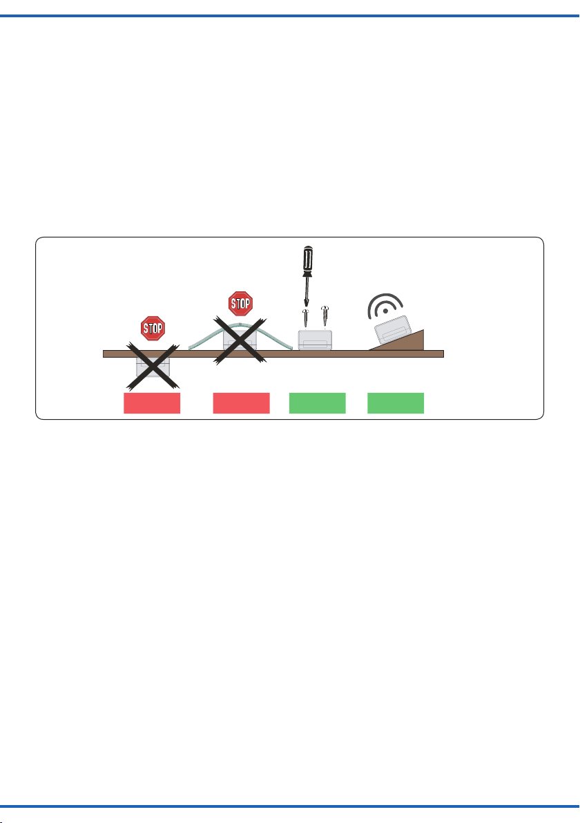
1. Der Lautsprecher ist im Modul integriert. Für eine gute
Schallverteilung darf die Oberseite des Moduls nicht
verdeckt sein.
2. Soundmodul möglichst in Richtung der Zuschauer/Zu-
hörer ausrichten, also keine Über-Kopf-Montage unter
der Anlage.
3. Das Soundmodul sollte sich dort befinden, wo das
entsprechende Funktionsmodell auf Ihrer Anlage vor-
kommt. Sie können das Modul auch auf der Anlage (z.
B. in einem Gebäude etc.) einbauen. So erreichen Sie
noch besseren Klang und eine bessere Übereinstim-
mung von sichtbarer und hörbarer Geräuschquelle.
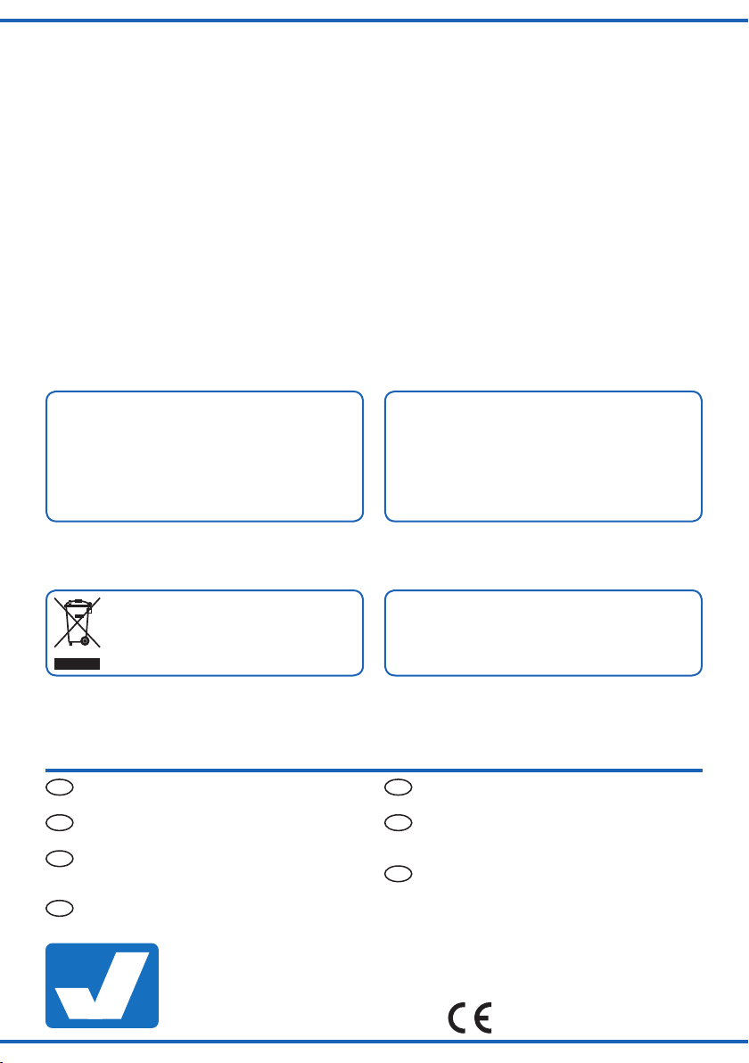
Einbaulage für Soundmodule
Mounting of sound modules
Lautsprecherschlitze nicht abdecken!
Mit Lautsprecher nach oben montieren!
Do not cover loudspeaker slots!
Mount the module with loudspeaker on top!
Falsch RichtigFalsch
wrong correctwrong
Optimal
ideal
Fig. 1
Abb. 1
4. Anschluss
Eine Spannung am Synchroneingang löst das Abspielen des
Sounds aus. Zunächst ertönt die akustische Startsequenz des
Helikopters, dann das normale Rotorgeräusch. Beim Öffnen
des Schalters ertönt das Auslaufgeräusch.
Geeignete Kabel: Der geringe Strombedarf des Soundmo-
duls erlaubt es, entsprechend klein dimensionierte Kabel,
die sich gut versteckt verlegen lassen, zu verwenden. Wir
empfehlen Litze mit einem Querschnitt von 0,14 mm² (z. B.
Viessmann Art. 6860 – 6869 oder 68603 – 68693).
Zum Betrieb des Soundmoduls beachten Sie bitte nachfolgen-
de Hinweise zu Verkabelung und Betrieb.
4.1 Anschluss des Synchronausgangs
Bei diesem Soundmodul steuert das Modul das Modell. Zum
Ein- und Ausschalten des Modells sowie des Soundmoduls
benötigen Sie einen Schalter, der an den Buchsen „Syn-
chroneingang“ angeschlossen ist. Hierzu empfehlen wir den
Universal-Ein-Aus-Umschalter Art. 5550 (Abb. 2).
4.2 Anschluss eines externen
Lautsprechers
Das Soundmodul verfügt über einen Ausgang für einen ex-
ternen Lautsprecher mit den elektrischen Werten min. 8 Ohm
Impedanz und min. 1 Watt Leistung (erhältlich im Elektronik-
Fachhandel). Bei Anschluss eines externen Lautsprechers
wird der eingebaute Lautsprecher ausgeschaltet.
3. Mounting
Fix the module with the enclosed screws. To ensure an
optimal sound reproduction of the module, please note the
following tips:
1. The loudspeaker is an integrated part of the module.
The upper surface of the module must always be un-
covered in order to enable a good sound dispersion.
2. The sound module must always be adjusted to the
direction of the spectator, so please no upside down
mounting under the layout.
3. The sound module should be installed close to the re-
spective functional model on your layout. You can also
install the module on the layout, e. g. in a building. This
way you can even have a better sound and an optimal
concordance between the visible and the audible sound
source.
4. Connection
To play a sound, an impulse to the synchronous input is
needed. The acoustic start sequence of the helicopter
sounds first, followed by the rotor sound. After opening up
the switch the running down sequence is played.
Fitting cables: Due to the low current consumption thin
cables can be used which can easily be hidden. It is
recommended to use a cross section of 0,14 mm² (e. g.
Viessmann items 6860 – 6869 or 68603 – 68693).
To operate the sound module, please observe the follow-
ing cabling and operating instructions.
4.1 Connection of the synchronized output
In case of these module, the sound module itself controls
the model. You need a switch to operate the model as well
as the sound module. The switch is connected to the con-
nection sockets “synchronous input”. Viessmann recom-
mends the universal on-off switch item 5550 (fig. 2)..
4.2 Connection of an external
loudspeaker
The sound module is equipped with an output for an exter-
nal loudspeaker with electrical values of 8 ohm impedance
at least and 1 watt power at least (can be purchased in a
specialized shop for electronics). In case you connect an
external loudspeaker the incorporated loudspeaker will be
switched off.

4
Fig. 2
Abb. 2
Sekundär
0-10-16 V~
16 V
Primär
230 V~
Gefertigt nach
VDE 0570
EN 61558
Lichttransformator
5200
Nur für trockene Räume
Primär 230 V 50 - 60 Hz
Sekundär max. 3,25 A52 VA
ta 25°CIP 40
10 V
0 V
viessmann 5550
Universal Ein-Aus-Umschalter
gelb
braun
z. B. / e. g. 5200
grün
5557
schwarz
z. B. / e. g. 5550
Gleichspannungsbetrieb:
Synchroneingang mit Pol der
Spannungsquelle verbinden.
Synchroneingang mit Pol der
Spannungsquelle verbinden.
/ brown
/ yellow
/ green
black
DC operation:
Connect “Synchroneingang” to
pole of the power supply.
Connect “Synchroneingang” to
pole of the power supply.
1. Ziehen Sie das kurze blaue, am Soundmodul befindliche
Kabel, aus der Buchse rechts daneben.
2. Isolieren Sie das blaue Kabel, so dass es keinen Kon-
takt mit anderen Kabeln haben kann.
3. Montieren Sie den externen Lautsprecher am vorgese-
henen Einbauort.
4. Verlegen Sie die beiden Anschlussleitungen des exter-
nen Lautsprechers zum Soundmodul.
5. Verbinden Sie die Anschlussleitungen mit den beiden
Buchsen gemäß Abb. 3.
Zum Anschluss eignen sich Stecker und Muffen wie bei-
spielsweise die Viessmann Art. 6875 (Stecker orange) und
Art. 6884 (Muffe orange).
Fig. 3
Abb. 3
Sekundär
0-10-16 V~
16 V
Primär
230 V~
Gefertigt nach
VDE 0570
EN 61558
Lichttransformator
5200
Nur für trockene Räume
Primär 230 V 50 - 60 Hz
Sekundär max. 3,25 A52 VA
ta 25°CIP 40
10 V
0 V
viessmann
5550
Universal Ein-Aus-Umschalter
orange
5557
isolieren
Lautsprecher
(mind. 8 Ω)
/ orange
/ insulate
Loudspeaker
(min. 8 Ω)
Anschluss eines externen Lautsprechers
Connection of an external loudspeaker
1. Please pull the short blue cable from the sound module
out of the socket right beside it.
2. Insulate the blue cable, to avoid any contact with other
cables.
3. Mount the external loudspeaker at the intended place.
4. Install the two wires of the external loudspeaker to the
sound module.
5. Connect the two wires to the two sockets according to
fig. 3.
You can use plugs and sockets for the connection, e. g.
Viessmann item 6875 (orange plug) and item 6884 (or-
ange socket).

5
4.3 Lautstärke einstellen
Sie können die Wiedergabelautstärke des Soundmoduls
einstellen. Diese Einstellung gilt sowohl für den eingebau-
ten als auch für einen alternativ vorhandenen externen
Lautsprecher. Zum Einstellen der Lautstärke verwenden
Sie bitte einen geeigneten Schraubendreher (Schlitz) wie
in Abb. 4 gezeigt:
- Lauter:
Drehen Sie das Potentiometer nach rechts.
- Leiser:
Drehen Sie das Potentiometer nach links.
Kleinen Schraubendreher benutzen!
Use a small screwdriver!
Fig. 4
Abb. 4
5. Fehlersuche und Abhilfe
Jedes Viessmann-Produkt wird unter hohen Qualitätsstan-
dards gefertigt und vor seiner Auslieferung geprüft. Sollte
es dennoch zu einer Störung kommen, können Sie anhand
der folgenden Punkte eine erste Überprüfung vornehmen.
Überprüfen Sie bitte als erstes die Stromzuführungen und
die Verkabelung.
Soundmodul spielt keinen Sound ab. Am externen
Lautsprecher ist kein Sound zu hören.
- Poti nach rechts drehen.
- Stellen Sie sicher, dass der kleine blaue Stecker am
unteren Gehäuserand des Soundmoduls aus der Buch-
se daneben entfernt und isoliert ist. Schließen Sie den
externen Lautsprecher gemäß Abb. 3 an.
- Diese Soundmodul spielt nur dann einen Sound ab,
wenn Spannung am Synchroneingang anliegt. Stellen
Sie den Anschluss sicher (Abb. 2).
Wenn Sie die Fehlerursache nicht finden und beheben
können, lesen Sie bitte das Kapitel 6 „Gewährleistung“.
4.3 Volume adjustment
The sound module is equipped with a volume control for
the sound. The adjustment is valid as well for the inte-
grated loudspeaker as for an external loudspeaker.
To adjust the volume, use a slotted screwdriver and pro-
ceed as follows (see fig. 4):
- Increase volume:
Turn the poti to the right.
- Reduce volume:
Turn the poti to the left.
5. Trouble-shooting
All Viessmann products are produced with high quality
standards and are checked before delivery. Should a fault
occur nonwithstanding, you can do a first check.
Please check first the power supply and the wiring.
No sound from the module. No sound from the exter-
nal loudspeaker.
- Turn the poti to the right.
- Please make sure that the small blue plug at the housing
of the sound module is removed from the socket and is
insulated. Connect the external loudspeaker as shown
in fig. 3.
- This sound module only plays a sound, if it receives a
signal from the synchronous input. Make sure they are
properly connected (fig. 2).
Please refer to chapter 6 “Warranty” if you cannot find the
cause of the failure and, therefore, cannot rectify it.

Modellbauartikel, kein Spielzeug! Nicht geeignet für Kinder
unter 14 Jahren! Anleitung aufbewahren!
Model building item, not a toy! Not suitable for children
under the age of 14 years! Keep these instructions!
Ce n’est pas un jouet. Ne convient pas aux enfants de
moins de 14 ans ! C’est un produit décor! Conservez cette
notice d’instructions!
Não é um brinquedo!Não aconselhável para menores de
14 anos. Conservar a embalagem.
Modelbouwartikel, geen speelgoed! Niet geschikt voor
kinderen onder 14 jaar! Gebruiksaanwijzing bewaren!
Articolo di modellismo, non è un giocattolo! Non adatto
a bambini al di sotto dei 14 anni! Conservare instruzioni
per l’uso!
Artículo para modelismo ¡No es un juguete! No
recomendado para menores de 14 años! Conserva las
instrucciones de servicio!
DE
EN
FR
NL
IT
ES
PT
Made in Europe
Viessmann
Modelltec
hnik GmbH
Bahnhofstraße 2a
D - 35116 Hatzfeld-Reddighausen
www.viessmann-modell.de
6
Änderungen vorbehalten. Keine Haftung für Druckfehler
und Irrtümer.
Die aktuelle Version der Anleitung finden Sie auf der Viess-
mann Homepage unter der Artikelnummer.
Subject to change without prior notice. No liability for
mistakes and printing errors.
You will find the latest version of the manual on the Viess-
mann website using the item number.
7. Technical data
Operation voltage: 10 – 16 V AC~
14 – 24 V DC=
Operation current: approx. 150 mA
Insulation: IP20
Temperature/humidity (operation): 0 – 40° C
Temperature/humidity (storage): -10 – 60° C
Weight: approx. 50 g
Dimensions: L 8,8 x W 5,3 x H 2,2 cm
7. Technische Daten
Betriebsspannung: 10 – 16 V AC~
14 – 24 V DC=
Betriebsstrom: ca. 150 mA
Schutzklasse/Isolation: IP20
Temperatur/Feuchtigkeit (Betrieb): 0 – 40° C
Temperatur/Feuchtigkeit (Lager): -10 – 60° C
Gewicht: ca. 50 g
Maße: L 8,8 x B 5,3 x H 2,2 cm
82110
Stand 01/sw
07/2019
Ho/Kf
Entsorgen Sie dieses Produkt nicht über den
(unsortierten) Hausmüll, sondern führen Sie
es der Wiederverwertung zu.
Do not dispose of this product through (unsorted)
domestic waste, supply it to recycling instead.
6. Gewährleistung
Jeder Artikel wurde vor Auslieferung auf volle Funktionalität
geprüft. Der Gewährleistungszeitraum beträgt 2 Jahre ab
Kaufdatum. Tritt in dieser Zeit ein Fehler auf und Sie finden
die Fehlerursache nicht, nehmen Sie bitte Kontakt mit uns
den Artikel zur Kontrolle bzw. Reparatur bitte erst nach
Rücksprache zu. Wird nach Überprüfung des Artikels ein
Herstell- oder Materialfehler festgestellt, wird er kostenlos
instandgesetzt oder ausgetauscht. Von der Gewährleistung
und Haftung ausgeschlossen sind Beschädigungen des
Artikels sowie Folgeschäden, die durch unsachgemäße
Behandlung, Nichtbeachten der Bedienungsanleitung, nicht
bestimmungsgemäßen Gebrauch, eigenmächtigen Eingriff,
bauliche Veränderungen, Gewalteinwirkung, Überhitzung
u. ä. verursacht werden.
6. Warranty
Each model is tested as to its full functionality prior to de-
livery. The warranty period is 2 years starting on the date
of purchase. Should a fault occur during this period please
contact our service department (service@viessmann-
modell.com). Please send the item to the Viessmann ser-
vice department for check and repair only after consulta-
tion. If we find a material or production fault to be the cause
of the failure the item will be repaired free of charge or
replaced. Expressively excluded from any warranty claims
and liability are damages of the item and consequential
damages due to inappropriate handling, disregarding the
instructions of this manual, inappropriate use of the model,
unauthorized disassembling, construction modifications
and use of force, overheating and similar.
Other manuals for 5557
1
Table of contents
Other Viessmann Recording Equipment manuals

Viessmann
Viessmann 55 Series User manual

Viessmann
Viessmann 5559 User manual

Viessmann
Viessmann 5575 User manual

Viessmann
Viessmann 5556 User manual

Viessmann
Viessmann 5574 User manual

Viessmann
Viessmann 5556 Instructions and recipes

Viessmann
Viessmann 5560 User manual

Viessmann
Viessmann 5574 User manual

Viessmann
Viessmann VITOCONNECT 100 Operating instructions

Viessmann
Viessmann VITOCONNECT OPTO2 User manual