8
Supported control units
For an up to date overview of the supported control
units: See www.viessmann.com/vitoconnect.
IP network
System requirements
■Wireless router with activated WiFi. The wireless
router must be protected by a sufficiently secure
WPA2 password. We advise against unencrypted
connection of the Vitoconnect 100 to a wireless
router.
■Internet connection with "flat rate" (tariff independ-
ent of time and data volume) and high availability,
i.e. the Vitoconnect 100 is permanently linked to the
Viessmann server.
■Have dynamic IP addressing (DHCP, factory setting)
on the network (WiFi) checked on site, and if
required set up, by an IT expert prior to commis-
sioning.
■Determine the routing and security parameters in the
IP network (LAN) as follows: Enable port 80,
port 123, port 443 and port 8883 for direct outward
connections. Have this checked and, if necessary,
set up on site by an IT expert before commissioning.
Note
During operation, the Vitoconnect 100 establishes a
secure internet connection to the Viessmann server.
Connecting the Vitoconnect 100 to any other type of
server is not possible.
User account
A valid user account on the Viessmann server is
required for the operation of the Vitoconnect 100,
regardless of which control device is used. Registra-
tion is automatic during commissioning via the ViCare
app: See page 13.
Control device for the ViCare app
The ViCare app supports mobile devices with the fol-
lowing operating systems:
■Apple iOS
■Google Android
Note
■For compatible versions: Go to App Store or Google
Play Store.
■Further information: Visit www.vicare.info.
Message destinations
Mobile device for receiving email, e.g. a computer,
smartphone or tablet.
Installation location
Installation type: Wall mounting
■Installation only in enclosed buildings
■The installation location must be dry and free of frost.
■Ensure ambient temperatures between −5 and
+40 °C.
■Distance to heat generator min. 0.3 m and max.
2.5 m
■Standard socket 230 V/50 Hz
or
US/CA: Socket 120 V/60 Hz
max. 1.5 m to installation location
■Internet access with adequate WiFi signal
Note
The WiFi signal strength can be increased with com-
mercially available WiFi repeaters.
Note
■Observe the lengths of the connecting cables provi-
ded when choosing the installation location.
■Establish a direct WiFi connection between Vitocon-
nect and the wireless router. If necessary, use on-
site wireless repeaters to amplify the WiFi signal.
Connecting cables Length
Plug-in power supply unit with power ca-
ble
1 m
Optolink cable for connecting the
Vitoconnect 100 to the boiler control unit
3 m
Ranges
The range of WiFi connections may be reduced by
walls, ceilings and interior fixtures. These weaken the
WiFi signal and can cause poor reception.
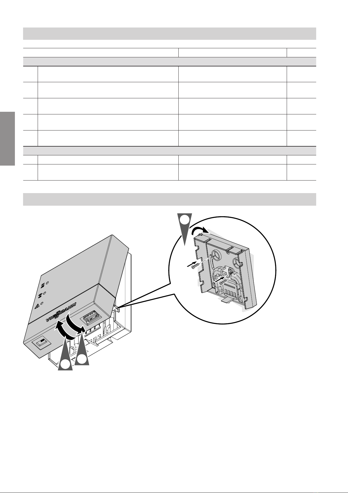
Preparing for installation
System requirements
5785665
Installation