Viessmann 5569 User manual

Bedienungsanleitung
Operation Manual
Innovation,
diebewegt!
5569
Soundmodul Hühnerhof
Sound module Chicken run
1. Wichtige Hinweise / Important information ........................................................ 2
2. Einleitung / Introduction..................................................................................... 2
3. Einbau / Mounting ............................................................................................. 2
4. Anschluss / Connection..................................................................................... 3
5. Fehlersuche und Abhilfe / Trouble-shooting ...................................................... 6
6. Technische Daten / Technical data.................................................................... 7
AC
~
DC
=

2
DE EN
1. Wichtige Hinweise
Bitte lesen Sie vor der ersten Anwendung des Produktes
bzw. dessen Einbau diese Bedienungsanleitung aufmerk-
sam durch. Bewahren Sie diese auf, sie ist Teil des Pro-
duktes.
1.1 Sicherheitshinweise
Vorsicht:
Verletzungsgefahr!
Für die Montage sind Werkzeuge nötig.
Stromschlaggefahr!
Die Anschlussdrähte niemals in eine Steckdose einfüh-
ren! Verwendetes Versorgungsgerät (Transformator,
Netzteil) regelmäßig auf Schäden überprüfen. Bei Schä-
den am Versorgungsgerät dieses keinesfalls benutzen!
Alle Anschluss- und Montagearbeiten nur bei abgeschal
-
teter Betriebsspannung durchführen!
Ausschließlich nach VDE/EN gefertigte Modellbahn-
transformatoren verwenden!
Stromquellen unbedingt so absichern, dass es bei einem
Kurzschluss nicht zum Kabelbrand kommen kann.
1.2 Das Produkt richtig verwenden
Dieses Produkt ist bestimmt:
- Zum Einbau in Modelleisenbahnanlagen und Dioramen.
- Zum Anschluss an einen Modellbahntransformator
(z. B. Art. 5200) bzw. an eine Modellbahnsteuerung mit
zugelassener Betriebsspannung.
- Zum Betrieb in trockenen Räumen.
Jeder darüber hinausgehende Gebrauch gilt als nicht be-
stimmungsgemäß. Für daraus resultierende Schäden haf-
tet der Hersteller nicht.
1.3 Packungsinhalt überprüfen
Kontrollieren Sie den Lieferumfang auf Vollständigkeit:
- Soundmodul mit blauem Stecker
- Montagematerial (2 Schrauben, 6 Stecker)
- Anleitung
2. Einleitung
Modellbahn mit allen Sinnen erleben: Das stationäre
Soundmodul ergänzt die Szenen der Bewegten Welten
um die passenden Geräusche. Das Soundmodul verfügt
über einen internen Lautsprecher und einen Anschluss für
einen externen Lautsprecher.
3. Einbau
Die Befestigung des Bausteins erfolgt mit den beiliegenden
Schrauben. Für optimalen Klang beachten Sie folgende
Hinweise:
1. Der Lautsprecher ist im Modul integriert. Für eine gute
Schallverteilung darf die Oberseite des Moduls nicht
verdeckt sein.
1. Important information
Please read this manual completely and attentively before
using the product for the rst time. Keep this manual. It is
part of the product.
1.1 Safety instructions
Caution:
Risk of injury!
Tools are required for installation.
Electrical hazard!
Never put the connecting wires into a power socket!
Regularly examine the transformer for damage. In case
of any damage, do not use the transformer.
Make sure that the power supply is switched o when
you mount the device and connect the cables!
Only use VDE/EN tested special model train transform-
ers for the power supply!
The power sources must be protected to avoid the risk
of burning cables.
1.2 Using the product for its correct purpose
This product is intended:
- For installation in model train layouts and dioramas.
- For connection to an authorized model train transformer
(e. g. item 5200) or a digital command station.
- For operation in dry rooms only.
Using the product for any other purpose is not approved
and is considered inappropriate. The manufacturer is not
responsible for any damage resulting from the improper
use of this product.
1.3 Checking the package contents
Check the contents of the package for completeness:
- Sound module with blue plug
- Mounting material (2 screws, 6 plugs)
- Manual
2. Introduction
Experience the model railway with all your senses: The
stationary sound module provides the specic sounds
to the scenes in the animated world. Sound module is
equipped with an integrated loudspeaker and a connec-
tion for an external loudspeaker.
3. Mounting
Fasten the module with the enclosed screws. To ensure
an optimal sound reproduction of the module, please note
the following hints:
1. The loudspeaker is an integrated part of the module.
The upper surface of the module must always be un-
covered in order to provide a good sound dispersion.

3
2. Soundmodul möglichst in Richtung der Zuschauer/Zu-
hörer ausrichten, also keine Über-Kopf-Montage unter
der Anlage.
3. Das Soundmodul sollte sich dort benden, wo das
entsprechende Funktionsmodell auf Ihrer Anlage vor-
kommt. Sie können das Modul auch auf der Anlage,
z. B. in einem Gebäude etc., einbauen. So erreichen
Sie noch besseren Klang und eine bessere Überein-
stimmung von sichtbarer und hörbarer Geräuschquelle.
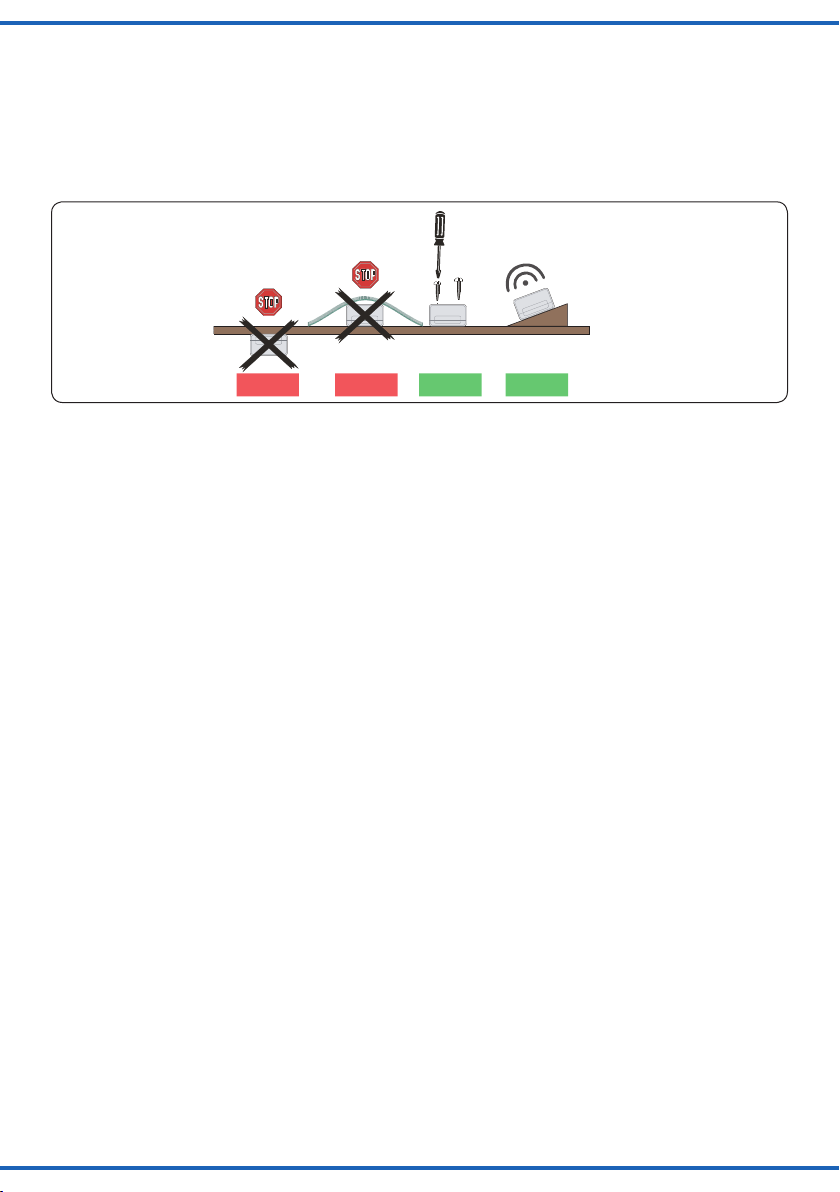
Einbaulage für Soundmodule
Mounting of sound modules
Lautsprecherschlitze nicht abdecken!
Mit Lautsprecher nach oben montieren!
Do not cover loudspeaker slots!
Mount the module with loudspeaker on top!
Falsch RichtigFalsch
wrong correctwrong
Optimal
ideal
Fig. 1
Abb. 1
4. Anschluss
Geeignete Kabel: Der geringe Strombedarf des Sound-
moduls erlaubt es, entsprechend klein dimensionierte Ka-
bel, die sich gut versteckt verlegen lassen, zu verwenden.
Wir empfehlen Litze mit einem Querschnitt von 0,14 mm²
(z. B. Viessmann Art. 6860 – 6869 oder 68603 – 68693).
Zum Betrieb des Soundmoduls beachten Sie bitte nachfol-
gende Hinweise zu Verkabelung und Betrieb.
Tipp: Das Soundmodul ist hervorragend zum Betrieb mit
dem H0 Hühnerhof, bewegt, Art. 1528 geeignet (Abb. 4).
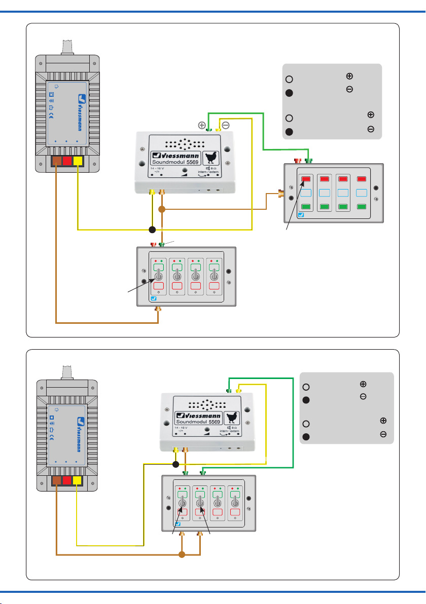
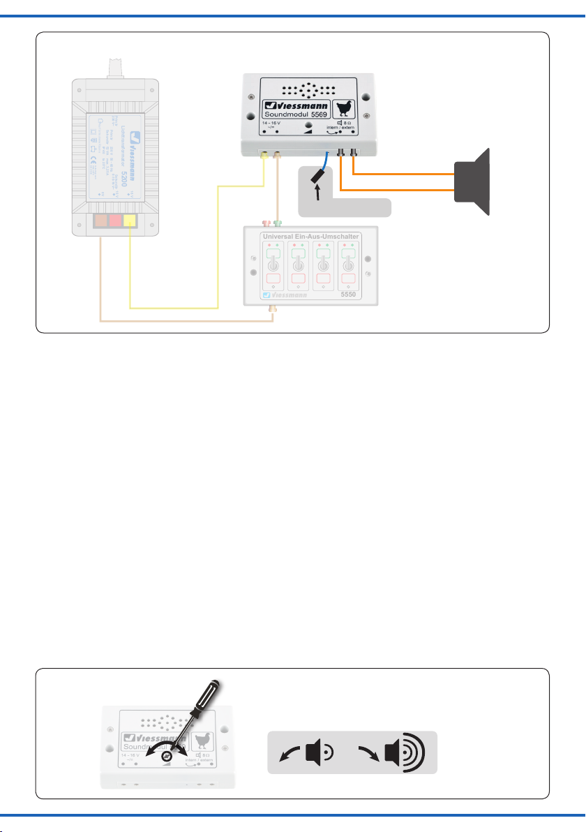
4.1 Sound wiedergeben
Zum Abspielen des Sounds, schließen Sie das Soundmo-
dul gemäß Abb. 2 an.
Mit dem Ein-Aus Umschalter (mit dem Buchstaben A mar-
kiert, Art. 5550) können Sie das Soundmodul ein- und aus-
schalten (Abb. 2). Nach Einschalten wird das Hühnerga-
ckern kontinuierlich abgespielt.
Durch Drücken der in Abb. 2 mit B markierten Taste, wird
das Hühnergackern um Hundegebell ergänzt.
Ist die Szene mit dem Hund abgespielt, wird durch erneu-
ten Druck der Taste B der Sound Hühnergackern um den
Ruf eines Greifvogels ergänzt.
Nach Beendigung dieser Szene wird durch nochmaligen
Druck der Taste B der Sound Hühnergackern um einen
Hahn und einen Schuss eines Gewehrs ergänzt.
Die Szenen lassen sich beliebig nacheinander abspielen.
Es ist nicht möglich während des Abspielens einer Szene
zu der nachfolgenden Szene zu wechseln.
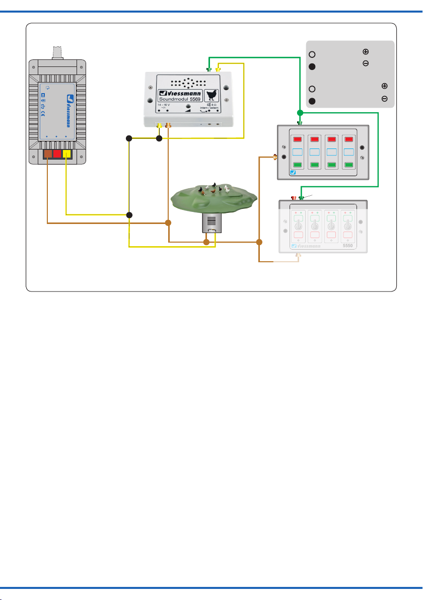
4.2 Automatikbetrieb
Schließen Sie das Soundmodul gemäß Abb. 3 an.
Nach Betätigen des Schalters (A) wird das Hühnergackern
kontinuierlich abgespielt. Durch die Betätigung des Schal-
ters (B) werden die Szenen Hund, Greifvogel und Schütze
(wie in Kapitel 4.1) alle 2 – 3 Minuten nacheinander abge-
spielt. Zum Verlassen des Automatikbetriebs schalten Sie
den Schalter wieder um.
2. If possible, gear the sound module towards the specta-
tor, so please avoid upside down mounting under the
layout.
3. The sound module should be installed near the respec-
tive functional model on your layout. You can also in-
stall the module on the layout, e. g. in a building. This
way you can even have a better sound and an optimal
concordance between the visible and the audible sound
source.
4. Connection
Fitting cables: Due to the low current consumption,
thin cables can be used which can easily be hidden. It is
recommended to use a cross section of 0.14 mm² (e. g.
Viessmann items 6860 – 6869 or 68603 – 68693).
To operate the sound module, please observe the follow-
ing cabling and operating instructions.
Hint: This sound module is perfectly suitable for operation
with the H0 Chicken run, moving, item 1528 (g. 4).
4.1 Playing Sound
To play the sound, connect the sound module acc. to g. 2.
By means of the on-o switch (marked with the letter A,
item 5550) you can turn the sound module on and o
(g. 2). When turned on, the chicken’s cackle is played
continuously.
By pushing the button marked with B in g. 2, the chicken’s
cackle is complemented by the sound of a barking dog.
Once the scene with the barking dog is nished and you
push button B again, the chicken’s cackle is complement-
ed by the cry of a bird of prey.
After this scene is nished, pushing the B key again adds a
rooster and a shot of a rie to the chicken cackling sound.
The scenes can be played in any order. It is, however, not
possible to switch to the next scene while one is playing.
4.2 Automatic mode
Connect the sound module acc. to g. 3.
After toggling the switch (A) the chicken cackling sound
is played continuously. When toggling the switch (B), the
scenes dog, bird of prey and shooter (as per chapter 4.1)
are played consecutively every 2-3 minutes. In order to
leave the automatic mode, you just ip the switch again.

4
Sekundär
0-10-16 V~
16 V
Primär
230 V~
Gefertigt nach
VDE 0570
EN 61558
Lichttransformator
5200
Nur für trockene Räume
Primär 230 V 50 - 60 Hz
Sekundär max. 3,25 A52 VA
ta 25°CIP 40
10 V
0 V
viessmann 5550
Universal Ein-Aus-Umschalter
grün / green
Tasten-Stellpult 2-begriffig
5547
Viessmann
gelb
braun
z. B. / e. g. 5200
grün
5569
z. B. / e. g. 5547
Gleichspannungsbetrieb:
Synchroneingang mit Pol der
Spannungsquelle verbinden.
Synchroneingang mit Pol der
Spannungsquelle verbinden.
/ brown
/ yellow
/ green DC operation:
Connect “Synchroneingang” to
pole of the power supply.
Connect “Synchroneingang” to
pole of the power supply.
braun / brown
Fig. 2
Abb. 2
B
A
Sekundär
0-10-16 V~
16 V
Primär
230 V~
Gefertigt nach
VDE 0570
EN 61558
Lichttransformator 5200
Nur für trockene Räume
Primär 230 V 50 - 60 Hz
Sekundär max. 3,25 A52 VA
ta 25°CIP 40
10 V
0 V
viessmann 5550
Universal Ein-Aus-Umschalter
gelb
braun
z. B. / e. g. 5200
gelb
Gleichspannungsbetrieb:
Synchroneingang mit Pol der
Spannungsquelle verbinden.
Synchroneingang mit Pol der
Spannungsquelle verbinden.
DC operation:
Connect “Synchroneingang” to
pole of the power supply.
Connect “Synchroneingang” to
pole of the power supply.
/ brown
/ yellow
yellow
grün / green
Fig. 3
Abb. 3
A B

5
Sekundär
0-10-16 V~
16 V
Primär
230 V~
Gefertigt nach
VDE 0570
EN 61558
Lichttransformator
5200
Nur für trockene Räume
Primär 230 V 50 - 60 Hz
Sekundär max. 3,25 A52 VA
ta 25°CIP 40
10 V
0 V
viessmann 5550
Universal Ein-Aus-Umschalter
gelb
braun
z. B. / e. g. 5200
grün
gelb
Universal Tasten - Stellpult
5547
Viessmann
Gleichspannungsbetrieb:
Synchroneingang mit Pol der
Spannungsquelle verbinden.
Synchroneingang mit Pol der
Spannungsquelle verbinden.
DC operation:
Connect “Synchroneingang” to
pole of the power supply.
Connect “Synchroneingang” to
pole of the power supply.
1528
/ brown
/ yellow
/ green
yellow
braun
brown
grün / green
Fig. 4
Abb. 4
4.3 Anschluss eines externen Lautsprechers
Das Soundmodul verfügt über einen Ausgang für einen ex-
ternen Lautsprecher mit den elektrischen Werten min. 8 Ohm
Impedanz und min. 1/2 Watt Leistung (erhältlich im Elektronik-
Fachhandel). Bei Anschluss eines externen Lautsprechers wird
der eingebaute Lautsprecher ausgeschaltet.
1. Ziehen Sie das kurze blaue, am Soundmodul befindliche Kabel,
aus der Buchse rechts daneben.
2. Isolieren Sie das blaue Kabel, so dass es keinen Kontakt mit an-
deren Kabeln haben kann.
3. Montieren Sie den externen Lautsprecher am vorgesehenen Ein-
bauort.
4. Verlegen Sie die beiden Anschlussleitungen des externen Laut-
sprechers zum Soundmodul.
5. Verbinden Sie die Anschlussleitungen mit den beiden Buchsen
gemäß Abb. 5.
ZumAnschluss eignen sich Stecker und Muffen wie beispielsweise die
ViessmannArt. 6875 (Stecker orange) und Art. 6884 (Muffe orange).
4.4 Lautstärke einstellen
Sie können die Wiedergabelautstärke des Soundmoduls
einstellen. Diese Einstellung gilt sowohl für den einge-
bauten als auch für einen alternativ vorhandenen exter-
nen Lautsprecher.
Zum Einstellen der Lautstärke verwenden Sie bitte einen
geeigneten Schraubendreher (Schlitz) wie in Abb. 6 gezeigt:
- Lauter:
Drehen Sie das Potentiometer nach rechts.
- Leiser:
Drehen Sie das Potentiometer nach links.
4.3 Connection of an external loudspeaker
The sound module is equipped with an output for an ex-
ternal loudspeaker with electrical values of min. 8 ohm im-
pedance and 1/2 a watt power at least (can be purchased
in a specialized shop for electronics). In case you connect
an external loudspeaker the incorporated loudspeaker will
be switched o.
1. Please pull the short blue cable from the sound module out
of the socket right beside it.
2. Insulate the blue cable to avoid any contact with other ca-
bles.
3. Mount the external loudspeaker at the intended place.
4. Install the two wires of the external loudspeaker to the sound
module.
5. Connect the two wires to the two sockets according to
g. 5.
You can use plugs and sockets for the connection, e. g. Viess-
mann item 6875 (orange plug) and item 6884 (orange socket).
4.4 Volume adjustment
The sound module is equipped with a volume control for
the sound. The adjustment is valid both for the integrated
loudspeaker and for an external loudspeaker.
To adjust the volume, use a slotted screwdriver and pro-
ceed as shown in g. 6:
- Increase volume:
Turn the poti to the right.
- Reduce volume:
Turn the poti to the left.
Optional für Automatikbetrieb
Optional for automatic mode
Table of contents
Other Viessmann Recording Equipment manuals

Viessmann
Viessmann VITOCONNECT OPTO2 User manual

Viessmann
Viessmann 5557 User manual

Viessmann
Viessmann 5577 User manual

Viessmann
Viessmann 5575 User manual

Viessmann
Viessmann 5574 User manual

Viessmann
Viessmann 5559 User manual

Viessmann
Viessmann 5560 User manual

Viessmann
Viessmann 5559 Instructions and recipes

Viessmann
Viessmann 5556 User manual

Viessmann
Viessmann 5560 User manual

Viessmann
Viessmann 5574 User manual

Viessmann
Viessmann Vitocom 100 Operating instructions

Viessmann
Viessmann 5556 User manual

Viessmann
Viessmann 5556 Instructions and recipes

Viessmann
Viessmann 55 Series User manual

Viessmann
Viessmann VITOCONNECT 100 Operating instructions

Viessmann
Viessmann 5572 User manual