Viewpro Falcon F390 User manual


ViewproUAV Tech. Ltd www.viewprouav.com
1 of 27
页
Content
Content............................................................................................................................................... 2
Warning...............................................................................................................................................2
1. Unmanned Aerial System.............................................................................................................3
1.1 The UAV frame........................................................................................................................3
1.2 Electronic equipment..............................................................................................................3
2. Installation....................................................................................................................................5
2.1 Body installation......................................................................................................................5
2.2 Add fuel...................................................................................................................................6
3. Preparation Before Flight.............................................................................................................6
3.1 Aircraft center of gravity inspection........................................................................................6
3.2 Turn on the ground equipment...............................................................................................6
3.3 Remote control logic check.....................................................................................................7
3.4 Engine Inspection....................................................................................................................8
3.5 RTK Inspection.........................................................................................................................9
3.6 Installing the rotor propeller...................................................................................................9
3.7 Notes on route planning.......................................................................................................10
4. Description of Flight Controller..................................................................................................10
5. RTK Description..........................................................................................................................14
6. EFI Engine Description................................................................................................................16
7. UBEC Description........................................................................................................................19
8. Charger.......................................................................................................................................19
9. Remote Control Instruction........................................................................................................20
10. Aircraft Description..................................................................................................................21
10.1 Aircraft Specification...........................................................................................................21
10.2 Block Diagram of Aircraft Load Equipment.........................................................................22
10.3 Schematic diagram of aircraft equipment installation location..........................................22
10.4 Aircraft Equipment Wiring Instructions..............................................................................23
10.5 Flow Chart of Flight Operations..........................................................................................24
11. Routine maintenance of F390 UAV..........................................................................................25

ViewproUAV Tech. Ltd www.viewprouav.com
2 of 27
页
Warning
Safety Rules
Warning
This product is a special control item, and incorrect operation may cause damage to
items, personnel
Injury or even death, the user must bear the corresponding criminal responsibility. In
order to use this device better and ensure your safety, please read the relevant
manual carefully before use, or consult the manufacturer.
Precautions
ATC
*All aircraft take off and must apply for approval from the local air traffic control
department.*
Flight area
It is prohibited to fly over airports, railways, highways, inflammable and explosive
goods warehouses (factories), dangerous goods warehouses (factories), power
stations, high-voltage lines, military facilities, densely populated areas, and no-fly
areas designated by relevant departments. And strictly abide by the flight
management regulations of the user's location. If there are important protection
targets or unclear targets in the planned flight area, in addition to reporting to the air
traffic control, it is also necessary to report to the local garrison for approval.
Regional environment
The flight area must be surveyed to ensure that there are no obstacles in the flight
path. There will be strong shear winds between buildings and mountain streams, and
flying in them is prohibited. Don’t smoke or put fire around the gas.
Personnel status
All operators have been trained by civil aviation-approved training institutions,
obtained training completion certificates, and corresponding operating models; and
have mastered the operation methods and clear tasks. All operators must ensure
that they are in good condition, full of energy, and concentrated. It is forbidden to
operate the UAV in a state of illness, emotion or fatigue. All operators are prohibited
from drinking alcohol the night before and until the end of the flight.

ViewproUAV Tech. Ltd www.viewprouav.com
3 of 27
1. Unmanned Aerial System
1.1 The UAV frame
①Fuselage
②Carbon tubes
③ Left wing
④Left arm
⑤ Horizontal tail
⑥ Right arm
⑦Tail screws
⑧ Wing screws
⑨ Right wing
1.2 Electronic equipment

ViewproUAV Tech. Ltd www.viewprouav.com
4 of 27
1. Liquid level sensor: Used to monitor the amount of oil in the fuel.
2. Airspeed meter : It’s used to measure airspeed
3. Flight control: used to control the aircraft to perform various tasks
4. UBEC: Used to power servo, receiver and other equipment
5. Starter ESC: Used to control the starter motor
6. Oil pump: Fuel a pressure is supplied to the engine fuel injection system
7. Engine controller: Engine brain,control, adjustment, adapt and other function
8. RTK module: Dual RTK orientation and positioning
9. Fuel tank: storage of the fuel
10. Electronic speed controller: control motor speed
11. Servo: Controls the movement of the rudder surface of the aircraft
12. RTK antenna: RTK antenna used to pick up satellite signals
13. Pitot tube: From here air passes through the tachometer to the flight controller
14. Motor: An airplane motor that turns the propeller to provide upward lift
15. Propeller: Used to provide upward lift for airplane
16. Engine: The driving force of aircraft cruising
17. Some electronic devices: Landing lights, step-down modules, Hall sensors, relays, etc

ViewproUAV Tech. Ltd www.viewprouav.com
5 of 27
2. Installation
2.1 Body installation
1. 2→1,Complete the assembly of two carbon tubes and the body
2. 3→1→9,Ensure that two pairs of MR60 and two pairs of MR30 are firmly connected,
lock the buckles and confirm that the lock is correct, complete the wing and fuselage
assembly
3. 3→4,Ensure that two pairs of MR60 and two pairs of MR30 are firmly connected, so that
with ⑧ wing screws, check the wire harness without pulling extrusion, complete the
assembly of left wing and hanging rod
4. 9→6,Make sure that two pairs of MR60 and one pair of MR30 are firmly connected, use
⑧ wing screws, check the wire harness without pulling extrusion, complete the
assembly of right wing and hanging rod
5. 4→5→6,Ensure a pair of MR30 firmly connected, so that the use of ⑦ flat end screws,
complete the flat end assembly
6. F390 assembled

ViewproUAV Tech. Ltd www.viewprouav.com
6 of 27
2.2 Add fuel
1. Gasoline and oil are mixed in a 40:1 ratio.
2. There is a refueling/pumping port at the rear of the right side of the fuselage. Pull out the
tubing plug to carry out refueling and pumping operations, and ensure that the tubing plug
and tubing are connected reliably.
3. Check regularly for oil leakage or blockage.
4. Add the amount of mixed fuel to TPU tank according to the task requirements.
3. Preparation Before Flight
3.1 Aircraft center of gravity inspection
Put the center of gravity plate on the carbon tube, adjust the handle rope from the front to
the fourth slot, and pick up the handle rope. After the drone is off the ground, the attitude
of the drone is flush with the horizontal plane, which means the F390 drone has a suitable
center of gravity for flying. It is recommended to use 4 pieces of 6S 8000mA/h (25c) for the
multi-rotor power battery of the drone, and the hovering time is about 6 minutes. The
position of the power harness is flexible. According to different loads, the battery installation
position can be adjusted arbitrarily, and the center of gravity can be adjusted.
The handle rope is adjusted from front to back to the fourth slot
3.2 Turn on the ground equipment
3.2.1 Turn on the remote control
Turn on the remote control and check that the joystick trims are all in the neutral position.
Check whether the lever movement is normal. (The default remote control is Japanese hand
control, please contact the manufacturer if you need to change it)

ViewproUAV Tech. Ltd www.viewprouav.com
7 of 27
a: Under the engine power switch (stop switch), the engine is turned off, there is no action in
the middle, and the upper is turned on
b: Airplane mode switch (three-stage switch)
c: Navigation light switch (three-stage switch)
d: Engine starter switch (self-reset segment switch)
Additional levers and knobs can be customized
3.2.2 Connect the aircraft to the main power
When mains power is applied, the plug and battery are connected out of sequence. Do not
move the aircraft within 2 minutes after the system is initialized (other power sources are
temporarily unavailable)
3.2.3 Ground station connection
Connect the remote control Bluetooth, the remote control Bluetooth name is
"SIYI-xxxxxxxxx". Open the mission planner software, select the serial port number mapped
by the remote controller's Bluetooth for the port, the baud rate is 57600, and connect.
3.3 Remote control logic check
3.3.1 Inspection of fixed-wing rudder surfaces
The ground station flight mode is set to Manual. Toggle the remote control to check whether
the corresponding rudder surface activity and logic are normal.
3.3.2 Check the throttle servo

ViewproUAV Tech. Ltd www.viewprouav.com
8 of 27
Set the flight mode of the ground station to Manual, the aircraft is unlocked, check whether
the throttle servo is moving normally, and whether the lever is good and stable.
3.4 Engine Inspection
3.4.1 Check the engine power switch
Turn on the engine battery, turn the engine power switch (stop switch) to on, and check that
the ECU light is on. Turn the engine power switch (turn off switch) to turn off the engine and
check that the ECU light is off.
3.4.2 Starting the engine
Connect the engine starter battery (12V30A/3S lipo battery), the starter self-checks for 3
seconds. Turn the engine power switch (stop switch) to ON. The ground station flight mode
is set to Manual, and the remote control unlocks the aircraft (make sure the rotor propeller
is not installed or removed before unlocking). Keep the throttle at the lowest level, start the
engine through the remote control lever, and release the start lever for 3 seconds (the
starter can be restarted after 20 seconds interval for 3 seconds). If the engine has not been
started 5 times. Please check wiring, switches and oil circuits.
3.4.3 Engine warm-up
Use the remote control throttle stick to control the engine and keep idling after 30-50
ViewproUAV Tech. Ltd www.viewprouav.com
9 of 27
seconds. Slowly push the throttle to the maximum and hold the maximum for 5-10 seconds.
Throttle idle for 10 seconds. Push the throttle to the engine speed of 3200-4000rpm, keep
the speed warm for 5-10 minutes (the temperature is below 10 degrees for more than 10-15
minutes). Idle the throttle for 10 seconds before turning it off. Engine warm-up completed
(engine warm-up can be placed before takeoff)
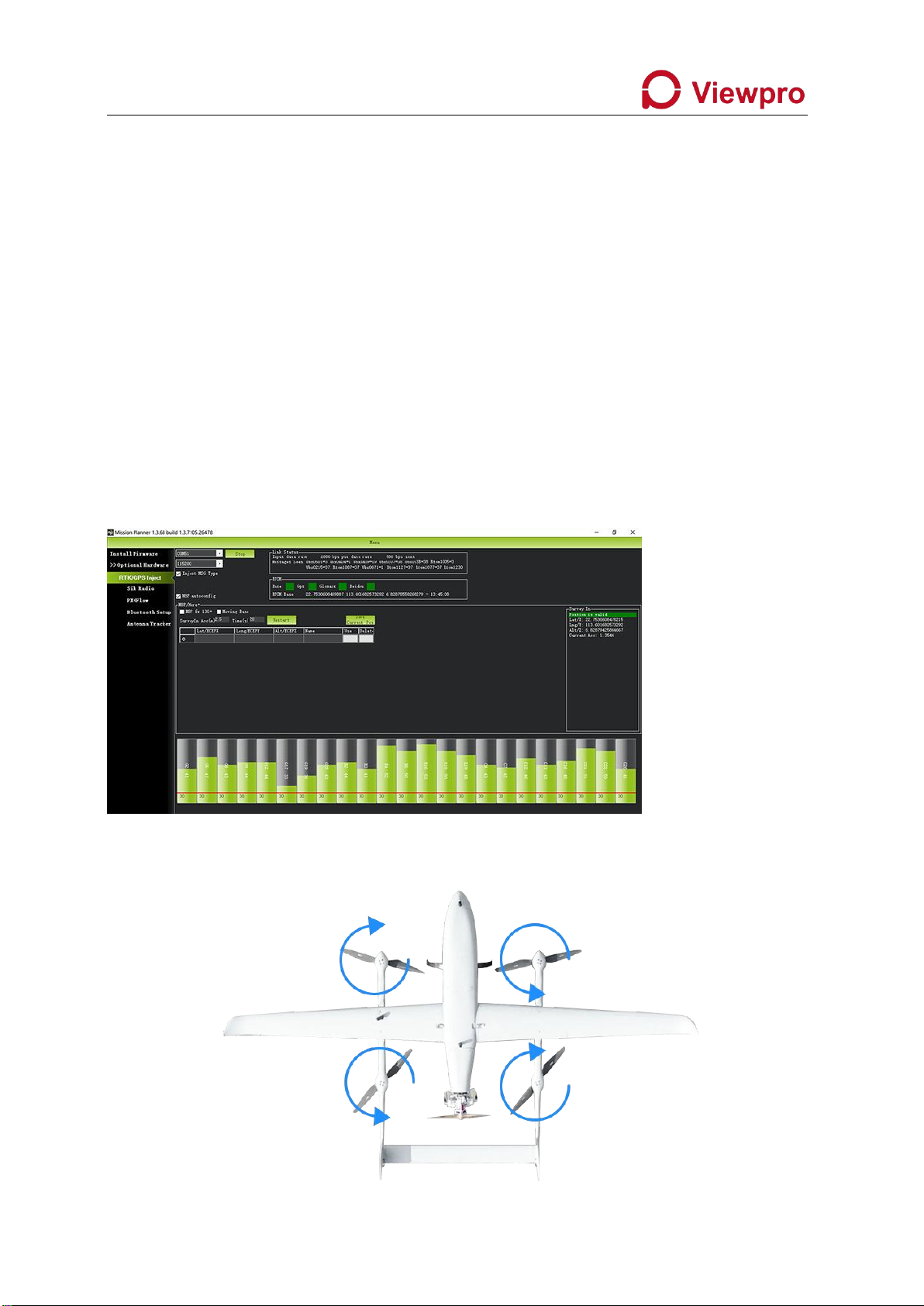
3.5 RTK Inspection
3.5.1 Dual RTK Orientation Check
Confirm that the ground station shows that at least one positioning status of GPS1 and GPS2
is RTK fixed, and the other positioning status is 3D positioning or RTK fixed. Turn the aircraft
to check that the heading is consistent with the actual heading.
3.5.2 RTK base station connection location check
After the base station is set up, use USB to connect the base station and the ground station
Initial settings - optional accessories - RTK/GPS inject - set serial port - click connect, all
green
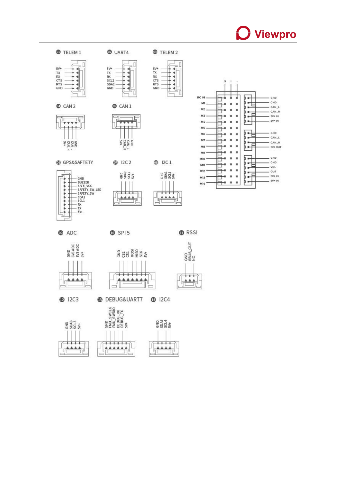
3.6 Installing the rotor propeller

ViewproUAV Tech. Ltd www.viewprouav.com
10 of 27
3.7 Notes on route planning
1. The turning radius of the aircraft is 200 meters.
2. It takes 260 meters to switch from multi-rotor to fixed-wing
3. When return in fixed wing mode and switch to multirotor mode for landing, please turn
off the engineer on RC manually after you see the FC mode is QRTL mode on GCS. (The
engine can only be turned off when the aircraft switches to QRTL flight mode).
4. It takes 300 meters for fixed-wing return and multi-rotor
5. The readings of the fuel level gauge are for reference only and are not used as the actual
fuel level. Please calculate the flight time according to the flight mission. (Fuel consumption:
35KG take-off weight, using DLE60 EFI engine, with 23x12 propeller, the throttle opening is
about 25%, the cruising speed is about 4900r, the measured fuel consumption is 0.9L/h.
Reserve enough fuel for return landing)
6. The switching height is 50-70 meters.
4. Description of Flight Controller
4.1 Specifications of flight controller
Processor
STM32H743
Sensor
Accelerometer
ADIS16470/ICM-20649/BMI088
Gyro
ADIS16470/ICM-20649/BMI088
Electronic compass
RM3100
barometer
MS5611*2
Interface
UART serial port
5
I2C
6 (4 separate i2c ports, two integrated in GPS/uart 4 ports)

ViewproUAV Tech. Ltd www.viewprouav.com
11 of 27
4.2 Definition of flight control interface
PWM output
14 (12 of them support dshot protocol)
Remote control signal
input protocol
PPM/SBUS/DSM
RC IN
1
RSSI input
PWM or 3.3V analog voltage
CAN standard bus
2
Power input
2 (Power A is the common ADC power detection interface;
Power C is the CAN galvanometer interface
Safety switch
1
GPS interface
2 (UART4 can be used as GPS2 interface)
Debug
1
JATG
1
ADC
1
USB interface
1
Supported Models
Ardupilot firmware
Fixed wing / 3-8 rotor / helicopter / VTOL vertical take-off and
landing / unmanned vehicle / unmanned boat, etc.
PX4 firmware
still in adaptation
Working environment and physical parameters
PM working voltage
4.5 ~ 5.5V
USB voltage
4.75 ~ 5.25V
Servo input
0 ~ 36v
Operating
temperature
-20 ~ 85°c
weight
101g

ViewproUAV Tech. Ltd www.viewprouav.com
12 of 27
ViewproUAV Tech. Ltd www.viewprouav.com
13 of 27

ViewproUAV Tech. Ltd www.viewprouav.com
14 of 27
5. RTK Description
5.1 RTK Specification
Satellite receiver type
184 channel Ubox F9P
Navigation Satellite
System
Beidou, Galileo, GLONASS, GPS / QZSS
Number of concurrent
navigation systems
4
Satellite band
GPS L1C/A L2C, GLONASS L1OF L2OF, GALILEO E1B/C E5b, BDS
B1I B2I, QZSS L1C/A L2C
Navigation refresh
rate
RTK up to 20 Hz
Positioning accuracy
RTK 0.01M+1ppm CEP
Convergence time
RTK<10S
Capture satellite
Cold start 24 s
Auxiliary start 2 s
Capture again for 2 s
Sensitivity
Tracking & Navigation: –167dBm
Cold start: –148dBm
Warm Start: –157dBm
Recapture: –160 dBm
Anti-interference
Active CW detection and cancellation
On-board filter

ViewproUAV Tech. Ltd www.viewprouav.com
15 of 27
Safety
Advanced Anti-Spoofing Algorithms
Interface
Serial
2 UARTs
USB
1
Antenna
Multi-satellite multi-frequency antenna
Time pulse
Configurable from 0.25hz to 10mhz
Data protocol
NMEA, UBX binary, RTCM 3.x
Other Information
Input voltage
4.5V to 6V
Operating
temperature
–40 °C to +85 °C
Size
31.5*48*12MM
weight
21g
5.2 RTK LED Status Light and Interface Definition

ViewproUAV Tech. Ltd www.viewprouav.com
16 of 27
6. EFI Engine Description
6.1 Engine Specifications
Performance :
7HP/8500rpm
Idle speed:
1400 rmp/min
Pull:
15.2kg/100 meters above sea level
Pull:
13.5kg/1800 meters above sea level
Applicable propeller
specifications:
22x10; 23x8; 23x10; 24x8
Applicable spark plug
models:
NGK CM6
Displacement:
60cc
Bore x Stroke:
36mm×30mm
Compression ratio:
7.6:1
Lubrication ratio:
30:1
Host weight:
1560g
Exhaust pipe weight:
200g

ViewproUAV Tech. Ltd www.viewprouav.com
17 of 27
Igniter Weight:
190g
Igniter Voltage:
4.8V-8.4V
6.2 Definition of engine interface

ViewproUAV Tech. Ltd www.viewprouav.com
18 of 27

ViewproUAV Tech. Ltd www.viewprouav.com
19 of 27
6.3 Maintenance timing
Item
Before Each
Takeoff
Every 25hrs
Every 50hrs
Every 100hrs
Pre-mix the
fuels
√
Sparking Plug
Checking
√
Sparking Plug
Replace
√
Air Filter
Replace
√
Fuel Filter
Replace
√
7. UBEC Description
UBEC interface definition
8. Charger
Specifications of the charger
Input voltage
100-240V
Output Power
1080W (540W x 2)
Discharge power
100W (50W x 2)
Charge current range
1.0-20.0A x 2
Maximum balance current
1.2A
Rechargeable battery type
LiPo/LiHV
Table of contents
Other Viewpro Drone manuals


