manuals.online logo
Brands
  1. Home
  2. •
  3. Brands
  4. •
  5. Parker
  6. •
  7. Industrial Equipment
  8. •
  9. Parker J Series Manual

Parker J Series Manual

Parker Hannifin Corporation
Filtration and Separation Division
Oxford, MI
OPERATION
Air coalescing is a continuous, balanced, steady-state process occuring at
or below rated flow, which depends on two factors for high performance:
(1) The bowl must be kept free of waste liquid build-up and (2) The element
must be replaced when the differential pressure reaches 6-10 psid, 12 psid
maximum. Differential pressure can be sensed at the inlet and outlet
ports by two gauges, or by observing system characteristics.
Bowl draining is accomplished by slowly opening the manual drain valves,
at least once every 8 hours depending on the liquid load. Finite's new High
Pressure Drain Kits are useful tools that can be utilized in order to safely
drain condensate from a high-pressure air / gas system. See Finite Bulletin
NP024 for more details.
A Finite coalescer, under normal system conditions, will operate for 6 to
12 months before reaching its maximum differential pressure. With shorter
coalescing element life a "PWC" series Particulate or"WS" Water Separa-
tor element should be employed ahead of the coalescer to increase its life.
A precoalescer (Grade 10) can also be used to extend the life of the high
efficiency coalescer (Grade 4).
Finite coalescers are designed for nominal operation with 10-20 wt.oil. Any
viscosity increase over that of 20 wt. oil must be offset by a proportionate
oversizing of the filter element. Consult your Finite representative.
PROBLEM PROBABLE CAUSE SOLUTION
Too High Initial Air flow excessive for housing size. Install larger filter.
Pressure Drop Filter media grade too fine. Install coarser element.
Too much oil/water from compressor. Pre-coalesce with grade 10 - oversize
housing.
Premature Clogging Lubricant improperly selected for compressor, Change oil, consult with lubricant
(Air Flow Drops Off) causing varnish or carbonizing of lubricant. supplier.
Excessive inlet particulate contamination. Prefilter with Particulate Filter.
Excessive lubricants present on element caused Prefilter with Grade 10 or 100WS and
by either high lubricant viscosity or very high oversize coalescer to compensate.
inlet aerosol level.
Oil/water emulsion forming on element. Remove water by drip leg, aftercooler.
Install mechanical separator upstream.
Oil Present Down- Bowl not properly drained of waste liquids. Drain regularly, use auto drain.
stream of Filter
Element not sealing. Replace element.
Filter piped backwards. See "INSTALLATION"; Re-pipe.
Filter being by-passed by valving. Close valve.
Contaminated air entering system from second Change pipe or relocate filter.
source downstream.
Oil vapors condensing downstream. Install an adsorber.
Excessive inlet oil level. Precoalesce with Grade 10 and
possibly oversize.
Element damaged, chemically attacked or not Change and consult distributor
installed in housing. or factory for other than neutral pH.
Oil present in pre-contaminated Clean piping.
downstream piping.
Maintenance Bulletin - J-Series
(J2SD, J2SL, J4SF, J4NF, J6SH, J6NH) MB-JSeries 04/05
INSTALLATION
Finite Coalescer "CWC", Particulate "PWC", Adsorber "AWC", Water Separator
"WS" filters and the desiccant cartridges "10JW" should be installed in a level
pipeline, mounted vertically, the bowl downward with one element length clear-
ance for element removal. The filter should be installed at the highest pressure
available, as near as possible to the equipment to be protected. It should also have
a drip leg immediately upstream. All filters should be visible and easily accessible
for periodic draining and maintenance.
The filters should be piped in accordance with the instruction tags and flow arrows.
Should these tags become unreadable, install the coalescer and water separator so
that flow passes through the filter tube from inside-to-outside. Plumb particulate
and adsorber filters so that flow passes through the filter from outside-to-inside.
The filter locations relative to other equipment should be as follows (unless specific
instructions are given to the contrary): (1 ) The COALESCER is placed before
the dryer.(2) The PARTICULATE or WATER SEPARATOR goes ahead of the
COALESCER when prefiltration is required. (3) The PARTICULATE is installed
downstream of desiccant dryers to prevent desiccant migration.(4) The ADSORBER
and DESICCANT CARTRIDGE are always preceded by a COALESCER.
MAINTENANCE
When Coalescer or Interceptor differential pressure reaches clogged condition
(6-10 PSID) replace element immediately. DO NOT ATTEMPT TO CLEAN
FILTER TUBE. System contamination can result. DO NOT ATTEMPT TO
RESEAT A FILTER TUBE. New serrated indentations can be formed causing
leakage. DO NOT BY-PASS THE COALESCER unless the by-pass line is also
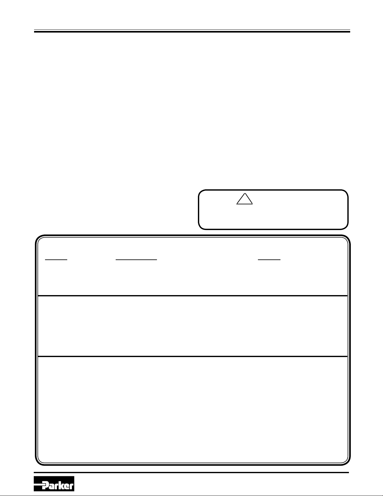
filtered. DANGER
Filter housings must be depressurized before
performing any maintenance activities, and depressurization
verified by a pressure gauge known to be in working order.
!
TROUBLESHOOTING CHART
Parker Hannifin Corporation
Filtration and Separation Division
Oxford, MI
Assembly Drawing/Parts List
(J2SD, J2SL, J4SF, J4NF, J6SH, J6NH)
J-SERIES REPLACEMENT PARTS J2SD J2SL J4NF J4SF J6NH J6SH
1) HEAD 40874 40874 40868 41149 40862 41148
2) ADAPTER BUSHINGS 70143 70143 N/A N/A N/A N/A
3) BOWL 40877 41703 40871 40871 40865 40865
4) ELEMENT STANDOFF 41684 41606 42111 42111 42112 42112
5) **DRAIN PLUG (WITH O-RING) 70172 70172 70172 70172 70172 70172
6) O-RING (HEAD-TO-BOWL) 75073V 75073V 75074V 75074V 75075V 75075V
7) SPRING N/A N/A 41082 41082 N/A N/A
GRADE 4 COALESCER 4CWC11-035 4CWC15-070 4CWC23-130
GRADE 10 COALESCER 10CWC11-035 10CWC15-070 10CWC23-130
PARTICULATE FILTER 3PWC11-035 3PWC15-070 3PWC23-130
CARBON ADSORBER AWC11-035 AWC15-070 AWC23-130
WATER SEPARATOR 100WS11-035 100WS15-070 100WS23-130
DESICCANT CARTRIDGE W/
ACTIVATED ALUMINA
N/A 10JWA15-070 10JWA23-130
DESICCANT CARTRIDGE W/
MOLECULAR SIEVE
N/A 10JWM15-070 10JWM23-130
**If drain plugs are used, the filter must be depressurized before the housing can be drained.
OPTIONAL ACCESSORIES—HIGH PRESSURE DRAIN KIT
Finite® high pressure drain kits are designed to safely remove condensate from a high pressure compressed
gas system. Each fully-assembled kit is constructed of 316 Stainless Steel and includes two needle valves,
fittings, and a pipe reservoir. For more details, please refer to
Finite® New Product Bulletin (NP024).
Horizontal Drain Kit
Vertical
Drain
Kit

This manual suits for next models

6

Other Parker Industrial Equipment manuals

Parker Greer BA Series Guide

Parker

Parker Greer BA Series Guide

Parker Gemini GV6K Series Manual

Parker

Parker Gemini GV6K Series Manual

Parker OLAER HY10-4005-UM/UK User manual

Parker

Parker OLAER HY10-4005-UM/UK User manual

Parker LORD User manual

Parker

Parker LORD User manual

Parker Phastite PH-8-HANDTOOL User manual

Parker

Parker Phastite PH-8-HANDTOOL User manual

Parker V402EP User manual

Parker

Parker V402EP User manual

Parker VM24 Series User manual

Parker

Parker VM24 Series User manual

Parker HTG Series Manual

Parker

Parker HTG Series Manual

Parker SAT Series User manual

Parker

Parker SAT Series User manual

Parker ETH User manual

Parker

Parker ETH User manual

Parker Parflange ECO 25 User manual

Parker

Parker Parflange ECO 25 User manual

Parker AC20 Series User manual

Parker

Parker AC20 Series User manual

Parker SCFT 02-02 Series User manual

Parker

Parker SCFT 02-02 Series User manual

Parker Bestobell Valves IOM 002 User manual

Parker

Parker Bestobell Valves IOM 002 User manual

Parker mSR080 Owner's manual

Parker

Parker mSR080 Owner's manual

Parker iqan-mc3 User manual

Parker

Parker iqan-mc3 User manual

Parker IQAN-LC5-C0 Series User manual

Parker

Parker IQAN-LC5-C0 Series User manual

Parker F11 series Guide

Parker

Parker F11 series Guide

Parker VMS-3 Owner's manual

Parker

Parker VMS-3 Owner's manual

Parker RC Series Technical specifications

Parker

Parker RC Series Technical specifications

Parker Helac PowerTilt Series Installation and operating manual

Parker

Parker Helac PowerTilt Series Installation and operating manual

Parker 2003-IP-00 User manual

Parker

Parker 2003-IP-00 User manual

Parker D-Pak Manual

Parker

Parker D-Pak Manual

Parker KarryFlare User manual

Parker

Parker KarryFlare User manual

Popular Industrial Equipment manuals by other brands

ABB +Q957 user manual

ABB

ABB +Q957 user manual

G.B.C BASIC EDGE 50 instruction manual

G.B.C

G.B.C BASIC EDGE 50 instruction manual

Tronair Batpak 11-6602-1000 Operation & service manual

Tronair

Tronair Batpak 11-6602-1000 Operation & service manual

Pilz PNOZ mi2p Operation manual

Pilz

Pilz PNOZ mi2p Operation manual

Clemco Zero BNP 6012 manual

Clemco

Clemco Zero BNP 6012 manual

Erskine Attachments V-Plow Operator's manual

Erskine Attachments

Erskine Attachments V-Plow Operator's manual

ABB HT610965 Operation manual

ABB

ABB HT610965 Operation manual

Morra MH 540 user manual

Morra

Morra MH 540 user manual

Eaton S090ST manual

Eaton

Eaton S090ST manual

GRIGGIO G 240 P4 instructions

GRIGGIO

GRIGGIO G 240 P4 instructions

Nexen AIR CHAMP HT45 user manual

Nexen

Nexen AIR CHAMP HT45 user manual

WTE V5 installation manual

WTE

WTE V5 installation manual

ABB HT845232 Operation manual

ABB

ABB HT845232 Operation manual

SMC Networks CJP Series Operation manual

SMC Networks

SMC Networks CJP Series Operation manual

JohnDow Industries JDI-AFT58 Operator's manual

JohnDow Industries

JohnDow Industries JDI-AFT58 Operator's manual

IMB MB9016A instruction manual

IMB

IMB MB9016A instruction manual

Clarke CUMB1 Assembly & operating instructions

Clarke

Clarke CUMB1 Assembly & operating instructions

amiad Arkal Spin Klin 2 user guide

amiad

amiad Arkal Spin Klin 2 user guide

manuals.online logo
manuals.online logoBrands
  • About & Mission
  • Contact us
  • Privacy Policy
  • Terms and Conditions

Copyright 2025 Manuals.Online. All Rights Reserved.