manuals.online logo
Brands
  1. Home
  2. •
  3. Brands
  4. •
  5. Viking
  6. •
  7. Irrigation System
  8. •
  9. Viking M Instruction manual

Viking M Instruction manual

1. PRODUCT NAME
Viking Model M
Extra Large Orifice Sprinkler
2. MANUFACTURER
THE VIKING CORPORATION
210 N. Industrial Park Road
Hastings, Michigan 49058 U.S.A.
Telephone: (616) 945-9501
(800) 968-9501
Fax Number: (616) 945-9599
From outside U.S.A.
Telephone: +1 (616) 945-9501
Fax Number: +1 (616) 945-9599
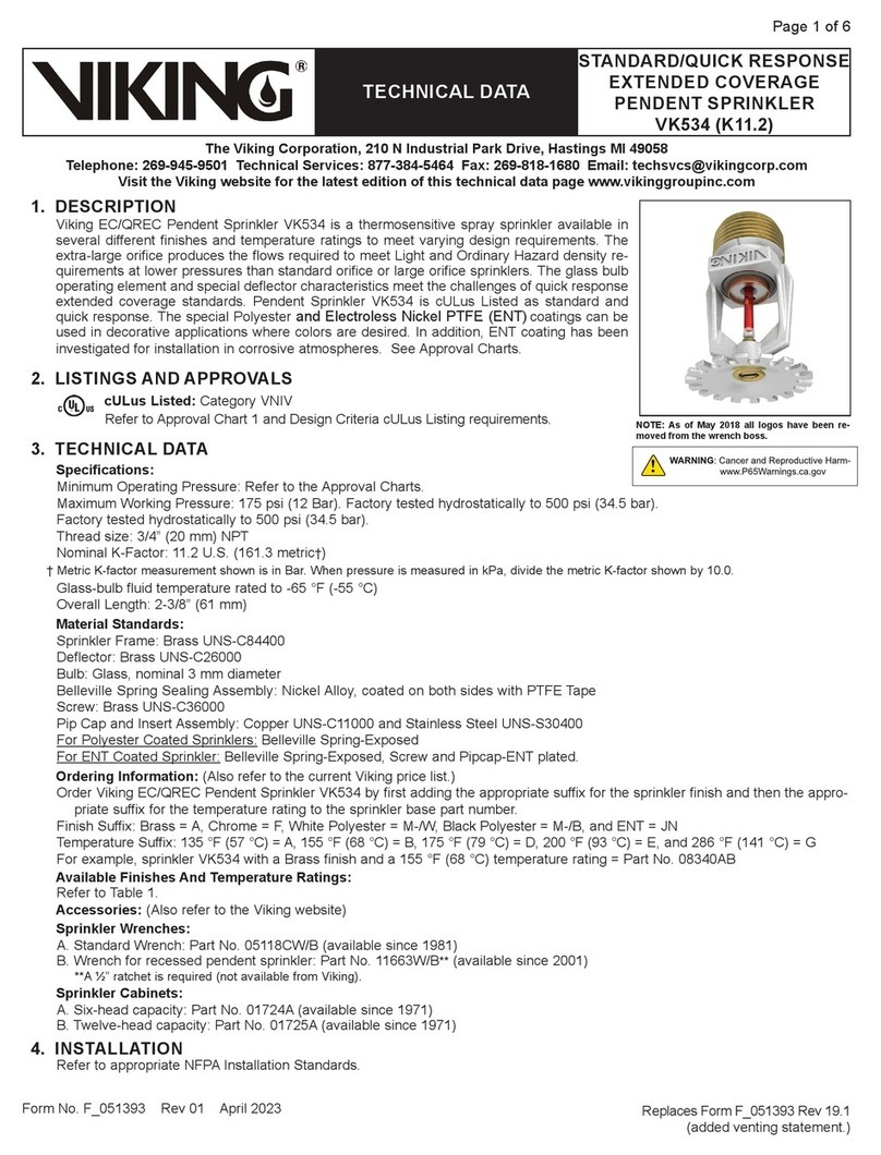
3. PRODUCT DESCRIPTION
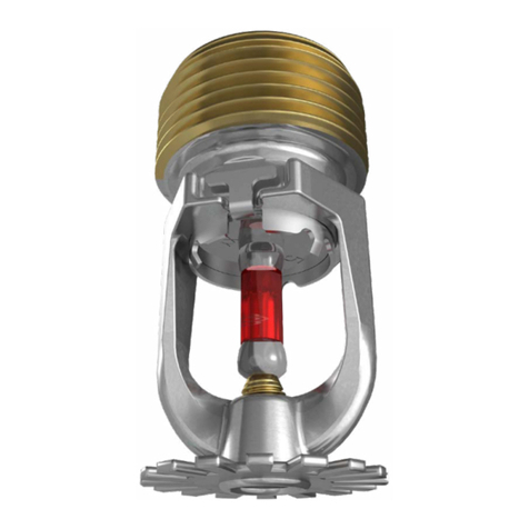
TheViking ModelM ExtraLargeOrifice
Sprinkler is a thermo-sensitive glass-
bulb spray sprinkler. A rugged 5mm
glass-bulb,anextralargeorifice,andthe
familiar Model M design, are combined
in thestandard responseModel MExtra
Large Orifice Sprinkler.
The extra large orifice provides greater
flows at lowerpressures thanthosepro-
ducedby standard orifice or largeorifice
sprinklers. This feature allows reduced
pipe sizing for hydraulically calculated
sprinkler systems which require high
densities of water. The Model M Extra
Large Orifice Sprinkler may eliminate
the need for a fire pump or reduce the
size of the pump if it is required. On
existing systems, replacing large orifice
sprinklers with extra large orifice sprin-
klers may provide the higher densities
required to allow an increase in the haz-
ard classification of an occupancy .
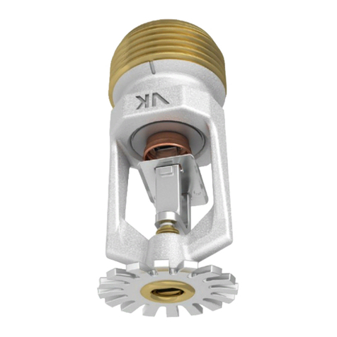
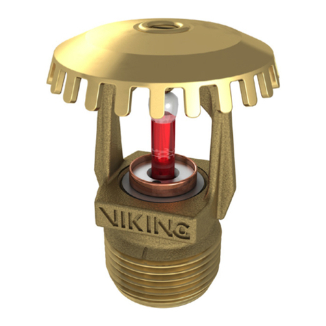
Viking Model M Extra Large Orifice
Sprinklers are available in both upright
and pendent styles with finishes and
temperature ratings to meet design re-
quirements. The special Teflon® and
polyestercoatingscan beusedindeco-
rative applications where colors are de-
sired. In addition, these two finishes are
corrosion resistant and provide protec-
tion against many corrosive environ-
ments.
During fireconditions, the heat sensitive
liquidintheglass-bulbexpands,causing
the bulb to shatter,releasingthe pip cap
andsealingspringassembly. Thewater
flowing through the sprinkler orifice
strikes the sprinkler deflector forming a
uniform spray pattern to extinguish or
control the fire.
Viking Model M Extra Large Orifice
Sprinklers may be ordered and/or used
as open sprinklers (glass-bulb and pip
capassembly removed) on deluge sys-
tems.
4. TECHNICAL DATA
See Chart(page13g)forlistofapprovals.
Glass Bulb Fluid Temperature rated to
-65oF (-55oC)
Rated 175 PSI (1 207 kPa) water work-
ing pressure
Factorytestedhydrostaticallyto500PSI
(3 448 kPa)
Thread size: 3/4 NPT (20mm)
Orifice Size: Nominal 5/8" (16mm)
KFactor:11.5 (16,6Metricforusewhen
pressure is measured in kPa)
Spring: USA Patent No. 4,167,974
Bulb: USA Patent No. 4,796,710
Spacing requirements: Refer to Ap-
proval Chart and Figure A
Minimum operating pressure require-
ments: Refer to to Approval Chart
and Figure A
Materials:
Frame: Brass castings UNS-C84400
Deflector: Brass UNS-C26000
Bulb: Glass; Nominal 5mm diameter
Seal: Teflon®Tape
Spring: Nickel Alloy
Form No. 010692
TECHNICAL DATA MODEL M
EXTRALARGE ORIFICE
SPRINKLER
Sprinkler 13 e
February 15, 1996
Replaces Sprinkler page 13 e, f, & g dated April 1, 1994
(Added FM Approved upright ELO.)
Note: Units of measure in parentheses may be approximations.
R
Sprinkler Nominal Sprinkler Ceiling Temperature at Sprinkler
Temperature Temperature Rating Max. Ambient Max. Recommend. Bulb
Classification (Fusing Point) Temp. Allowed1Ambient Temp.2Color3
Ordinary 135oF(57oC) 115oF(46oC) 100oF(38oC) Orange
Ordinary 155oF(68oC) 135oF(57oC) 100oF(38oC) Red
Intermediate 175oF(79oC) 155oF(68oC) 150oF(65oC) Yellow
Intermediate 200oF(93oC) 180oF(82oC) 150oF(65oC) Green
High 286oF(141oC) 266oF(130oC) 225oF(107oC) Blue
Sprinkler Finishes: Brass, Polished Chrome, Black Teflon®and White Polyester.
Corrosion Resistant Coatings4: Black Teflon®and White Polyester in all temperatures and
Wax coated brass in the following temperatures:
135oF(57oC) White Wax 175oF(79oC) Dark Brown Wax
155oF(68oC) Light Brown Wax 200oF(93oC) Dark Brown Wax.
1Based on National Fire Prevention and Control Administration Contract No. 7-34860.
2Based on NFPA-13. Other limits may apply depending on fire loading, sprinkler location and other
authority having jurisdiction requirements. Refer to specific installation standards.
3Temperature rating is stamped on deflector.
4The Corrosion Resistant Coatings have passed the standard corrosion test required by the listed
approving agencies. These tests cannot and do not represent all possible corrosive environments. Prior
to installing, verify through the end user, that the coatings are compatible or suitable for the proposed
environment. The coatings indicated are applied to the exposed exterior surfaces only and therefore
cannot be used as open sprinklers. Note that the spring is exposed on the Teflon®coated sprinkler
and the White Polyester sprinkler.
Pendent
Upright
The Viking Model M Extra
Large Orifice Upright Sprinkler
is UL listed and FM Approved
for use in High Piled Storage
Occupancies.
See Approval Chart and Figure A.
When acceptable to the
Authority Having Jurisdiction,
Viking Model M Extra Large Orifice
Upright sprinklers may be used to
protect single, double, multiple-row,
and portable rack storage of Class
I-IV group Aand B plastics, cartoned,
expanded or unexpanded, as well as
exposed unexpanded with:
a maximum storage height of
20 ft. (6,1 m),
a maximum ceiling height of
25 ft. (7,6 m),
36 inches (914,4 mm) minimum
deflector to top of storage
clearance,
design density of 0.60 gpm/sq. ft.
(24,5 l/min/sq. meter), and a
design area of
2000 sq. ft. (186 sq. meters)
for wet systems or
2600 sq. ft. (242 sq. meters),
for dry systems.
OBSOLETE
TECHNICAL DATA MODEL M
EXTRA LARGE ORIFICE
SPRINKLER
Sprinkler 13 f February 15, 1996
R
UL & ULC Spacing and Minimum Pressure Requirements*
Maximum Spacing (UL & C-UL Upright and UL & ULC Pendent)
Ordinary Hazard Occupancies (UL & C-UL Upright and UL & ULC Pendent):
130 Ft2(12,0 m2)
Extra Hazard Occupancies (UL & C-UL Upright and UL & ULC Pendent):
90 Ft2( 8,4 m2) for pipe schedule systems.
100Ft2( 9,3 m2) for systems hydraulically calculated according to NFPA 13 with densities of .25 GPM/Ft2(10,2 L/min/m2)
or greater.
130 Ft2( 12,1 m2) for systems hydraulically calculated according to NFPA 13 with densities less than .25 GPM/Ft2(10,2
L/min/m2).
High Piled Storage (UL & C-UL Upright):
100Ft2(9,3m2)forsystemshydraulicallycalculatedaccordingtoNFPA 231, 231C,or231Dwithdensitiesof.25GPM/Ft2
(10,2 L/min/m2) or greater.
130 Ft2( 12,1 m2) for systems hydraulically calculated according to NFPA 231, 231C, or 231 D with densities less than
.25 GPM/Ft2(10,2 L/min/m2).
Maximum Distance Between Sprinklers (UL & C-UL Upright and UL & ULC Pendent)
Ordinary Hazard Occupancies (UL & C-UL Upright and UL & ULC Pendent):
15 Ft (4,6 m)
Extra Hazard Occupancies (UL & C-UL Upright and UL & ULC Pendent):
12 Ft (3,7 m) -
Exception #1: Maximum distance between sprinklers = 12’-6" (3,8 m) in bays 25 ft. (7,6 m) wide.
Exception #2: Maximum distance between sprinklers = 15’-0" (4,6 m) for systems hydraulically
calculated according to NFPA 13 with densities less than .25 GPM/Ft
2 (10,2 L/min/m2).
High Piled Storage Occupancies (UL & C-UL Upright):
12 Ft (3,7 m) -
Exception #1: Maximum distance between sprinklers = 12’-6" (3,8 m) in bays 25 ft. (7,6 m) wide.
Exception #2: Maximum distance between sprinklers = 15’-0" (4,6 m) for systems hydraulically
calculated according to NFPA 13 with densities less than .25 GPM/Ft
2 (10,2 L/min/m2).
Minimum Distance Between Sprinklers (UL & C-UL Upright and UL & ULC Pendent)
Ordinary Hazard & Extra Hazard (UL & C-UL Upright and UL & ULC Pendent)
6 Ft (1.8 m) -
Unless provided with baffles installed according to NFPA 13
High Piled Storage Occupancies (UL & C-UL Upright only):
6 Ft (1.8 m) -
Unless provided with baffles installed according to NFPA 13
Minimum Operating Pressure (UL & C-UL Upright and UL & ULC Pendent)
Ordinary Hazard & Extra Hazard (UL & C-UL Upright and UL & ULC Pendent)
7 PSI (48,3 kPa)
High Piled Storage Occupancies (UL & C-UL Upright only):
10 PSI (70 kPa)
FM** Approval Spacing & Minimum Pressure Requirements
Maximum Spacing (FM Upright only)
Ordinary Hazard, Extra Hazard, and High Piled Storage Occupancies (FM Upright only):
100 Ft2(9,3 m2)
Maximum Distance Between Sprinklers (FM Upright only)
Ordinary Hazard, Extra Hazard, and High Piled Storage Occupancies (FM Upright only):
12 Ft (3,7 m)
Minimum Distance Between Sprinklers (FM Upright only)
Ordinary Hazard, Extra Hazard, and High Piled Storage Occupancies (FM Upright only):
7 Ft (2,1 m)
Minimum Operating Pressure (FM Upright only)
Ordinary Hazard, Extra Hazard, and High Piled Storage Occupancies (FM Upright only):
10 PSI (70 kPa) Figure A
Listing and Approval Spacing and Minimum Pressure Requirements Requirements
*UL, ULC, & C-UL listing of ELO Sprinklers requires installation to comply with recommendations set forth in NFPA Installation Standards. UL, ULC, & C-UL
spacing and minimum pressure requirements shown are taken from NFPA 13 (1994 ed.), 231 (1995ed.), 231-C (1995ed.), and 231-D (1994 ed)and areprovided
for reference only.
**For FM Approval, installation must compy with requirements of applicable Factory Mutual Loss Prevention Data Sheets.
OBSOLETE
Pintle Screw: Brass UNS-C36000.
Pip Cap: Copper UNS - C31600
Teflon®Sprinklers:
Spring: Nickel Alloy; Exposed
Pintle Screw: Brass UNS-C36000
Tin plated, painted black for
appearance only
Pip Cap: Leaded Bronze
UNS-C31600
**Teflon®coated
Polyester Sprinklers:
Spring: Nickel Alloy; Exposed
Pintle Screw: Brass UNS-C36000
Tin plated, painted white for
appearance only
Pip Cap: Leaded Bronze
UNS-C31600
Tin plated
*
Accessories:
Sprinkler Wrench
Standard ELO wrench:
PN 07297M
Wrench for coated & recessed ELO
sprinklers:
PN 07565W/B (1/2" ratchet required)
Available Finishes:
Chrome, Brass, Black Teflon® or
White Polyester
5. AVAILABILITY AND SERVICE
Viking sprinklers are available through a
network of Domestic, Canadian, and In-
ternational Distributors, see the Yellow
Pages of the telephone directory (listed
under “Sprinklers Automatic Fire”) or
write to The Viking Corporation.
6. GUARANTEES
For details of warranty, refer to Viking’s
current list price schedule or contact Vi-
king directly.
7. INSTALLATION
WARNING: Viking sprinklers are manu-
factured and tested to meet the rigid
requirements of the approving agency.
The sprinklers are designed to be in-
stalled in accordance with recognized
installation standards. Deviation from
the standards or any alteration to the
sprinkler after it leaves the factory in-
cluding, but not limited to, painting,
plating,coatingormodification,may
render the sprinkler inoperative and will
automatically nullify the approval and
any guarantee made by The VikingCor-
poration.
A. Sprinklers are to be installed in ac-
cordance with the latest published
standardsoftheNationalFireProtec-
tion Association, Factory Mutual,
LossPreventionCouncil,Assemblee
Pleniere, Verband der Sachver-
sicherer or other similar organiza-
tions and also with the provisions of
governmentalcodes,ordinancesand
standards whenever applicable. The
use of Extra Large Orifice sprinklers
maybelimitedduetooccupancy and
hazard. Refer to the Authority Hav-
ing Jurisdiction prior to installation.
B. Sprinklers must be handled withcare.
They must be stored in a cool, dry
place in their original shipping con-
tainer. Never install sprinklers that
have been dropped, damaged or ex-
posed to temperatures in excess of
TECHNICAL DATA MODEL M
EXTRA LARGE ORIFICE
SPRINKLER
Sprinkler 13 g
February 15, 1996
MODEL M 5mm GLASS BULB
STANDARD RESPONSE
Thread Nominal Deflector Nominal Overall Approval 2
Size Orifice Style K Factor 3 Length
N.P.T. B.S.P. Inches MM Description Base P/N1U.S. Metric Inches MM UL4ULC4C-UL5NYC6FM7
A2X A2X -- A3X
3/4" 20mm 5/8" 16 Pendent 07961 11.5 16,6 2.75 69,9 B2Y B2Y -- B3Y --
B4X B4X -- B4X
D2 -- D2 --
3/4" 20mm 5/8" 16 Upright 09679 11.5 16,6 2.75 69,9 E4 -- E4 -- D1
C5 -- C5 --
APPROVED FINISHES
1 - Brass, Chrome
2 - Brass, Chrome, Black Teflon®,and White Polyester
3 - Brass, Chrome, and Black Teflon®
4 - Wax coated Brass. Corrosion Resistant
5 - Brass with 200oF (93oC) wax coating. (For corrosion
resistance.) Maximum ambient ceiling temperature
at ceiling = 150OF (65OC).
1 Base part number shown. For complete part number, see price list.
2 This Chart shows the listings and approvals available at the time of printing. Other approvals are in process. Check with the
manufacturer for any additional approvals.
3 Metric K Factor shown is for use when pressure is measured in kPa. When pressure is measured in BAR, multiply the
metric K Factor shown by 10.0.
4 For UL and ULC listing requirements concerning ELO sprinkler spacing and minimum pressure requirements, refer to Figure A and
applicable installation standards.
5Listed by Underwriters Laboratories Inc. for use in Canada.
6 Accepted for use, City of New York Department of Buildings MEA 89-92-E Vol. III.
7 For FM Approval requirements concerning ELO sprinkler spacing and minimum pressure requirements, refer to Figure A. Also refer to
applicable FM Loss Prevention Data sheets.
A1X
EXTRA LARGE ORIFICE
FOOTNOTES
APPROVED TEMPERATURES
A - 135OF (57OC), 155OF(68OC), 175OF ( 79OC),
200OF (93OC), 286OF (141OC)
B - 135OF (57OC), 155OF(68OC), 175OF ( 79OC),
200OF (93OC)
C - 286OF (141OC)
D - 155OF(68OC), 175OF ( 79OC), 200OF (93OC),
286OF (141OC)
E - 155OF(68OC), 175OF ( 79OC), 200OF (93OC)
KEY
Temperature
Finish
Escutcheon (Pdt. Sprinkler only)
APPROVED ESCUTCHEONS
X - Standard (surface)
Y - Standard (surface) or
recessed with E-1
escutcheon
R
OBSOLETE
the maximum ambient temperature
allowed. Never install any glass bulb
sprinkler if the bulb is cracked or if
there is a loss of liquid from the bulb.
(These sprinklers should be de-
stroyed immediately).
C. Corrosion resistant sprinklers must
beinstalledwhensubjecttocorrosive
atmospheres. When installing corro-
sion resistant sprinklers, take care
nottodamagethecorrosionresistant
coating. Use only the special wrench
designed for installing coated Viking
sprinklers (any other wrench may
damage the unit).
D. The sprinkler must be installed after
the piping is in place to prevent me-
chanical damage. Before installing,
make sure the appropriate model,
style, orifice size and temperature
rating are used.
1. Install escutcheon, (if used) which
is designed to thread on to the
external threads of the sprinkler.
Refer to "Sprinkler Accessories"
for approved escutcheons and
other accessories.
2. Apply a small amount of pipe joint
compound or tape to the external
threads of the sprinkler only, tak-
ing care not to allow a build up of
compound in the sprinkler inlet.
3. Install the sprinkler on the piping
using the special sprinkler wrench
only, taking care not to over-
tighten or damage the sprinkler
operating parts. DO NOT use the
deflector to start or thread the
sprinkler into a fitting.
E. After installation, the entire sprinkler
systemmustbetestedinaccordance
with the recognized installation
standards. The test is applied after
the sprinkler installation to insure no
damagehasoccurredtothesprinkler
during shipping and installation, and
to make sure the sprinkler has been
properly tightened. If a thread leak
should occur, normally the sprinkler
must be removed, new pipe joint
compound or tape applied and rein-
stalled. This is due to the fact that
when the joint seal is damaged, the
sealing compound or tape is washed
out of the joint. Air testing the sprin-
kler piping prior to testing with water
may be considered in areas where
leakage during testing must be pre-
vented. Refer to the Installation
Guides, andthe Authority HavingJu-
risdiction.
F. Sprinklers must be protected from
mechanical damage. Wet pipe sys-
temsmustbeprovidedwithadequate
heat. When installing Extra Large
Orifice Sprinklers on dry systems,
refer to the Installation Guides, and
the Authority Having Jurisdiction.
8. MAINTENANCE
NOTICE: The owner is responsible for
maintaining the fire protection system
and devices in proper operating condi-
tion. For minimum maintenance and in-
spection requirements, refer to the Na-
tional Fire Protection Association Pam-
phlet that describes care and mainte-
nance of sprinkler systems. In addition,
the Authority Having Jurisdiction may
have additional maintenance, testing
andinspectionrequirementswhichmust
be followed.
A. The Sprinklers must be inspected on
a regular basis for corrosion, me-
chanical damage, obstructions,
paint, etc. The frequency of the in-
spections may vary due to corrosive
atmospheres,water suppliesandac-
tivity around the device.
B. Sprinklers that have been painted or
mechanically damaged must be re-
placed immediately. Sprinklers
showing signs of corrosion shall be
tested and/or replaced immediately
as required. Standard response
Sprinklers that are 50 years old shall
be tested and/or replaced as re-
quired. Sprinklers that have oper-
ated cannot be reassembled or re-
used, but must be replaced. When
replacing sprinklers, use only new
sprinklers.
C. The sprinkler discharge pattern is
critical for proper fire protection,
therefore, nothing should be hung
from, attached to, or otherwise ob-
struct the discharge pattern. All ob-
structions must be immediately re-
moved or, if necessary, additional
sprinklers installed.
D. When replacing existing sprinklers,
the system must be removed from
service. Refertotheappropriatesys-
tem description and/or valve instruc-
tions. Prior to removing the system
from service, notify all Authorities
Having Jurisdiction. Consideration
should be given to employment of a
fire patrol in the affected area.
1. Remove the system from service,
draining all water and relieving all
pressure on the piping.
2.Usingthespecialsprinklerwrench,
remove the old sprinkler and in-
stall the new unit. Care must be
taken to replace the sprinkler with
the proper model, style, orifice
size and temperature rating. A
fully stocked spare sprinkler cabi-
net should be provided for this
purpose.
3. Place the system back in service
and secure all valves. Check and
repair all leaks.
E. Sprinkler systems that have been
subjected to a fire must be returned
to service as soon as possible. The
entire system must be inspected for
damage and repaired or replaced as
necessary. Sprinklers that have
been exposed to corrosive products
of combustion or high ambient tem-
peratures, but have not operated,
should be replaced. Refer to the
AuthorityHavingJurisdictionformini-
mum replacement requirements.
Form No. 010692
Replaces Sprinkler page 13 e, f, & g dated April 1, 1994
(Added FM Approved upright ELO.)
TECHNICAL DATA MODEL M
EXTRA LARGE ORIFICE
SPRINKLER
Sprinkler 13 h February 15, 1996
R
Figure B
OBSOLETE

Other manuals for M

6

Other Viking Irrigation System manuals

Viking FREEDOM VK466 Instruction manual

Viking

Viking FREEDOM VK466 Instruction manual

Viking M Instruction manual

Viking

Viking M Instruction manual

Viking VK503 Instruction manual

Viking

Viking VK503 Instruction manual

Viking HQR-2 Instruction manual

Viking

Viking HQR-2 Instruction manual

Viking M Instruction manual

Viking

Viking M Instruction manual

Viking VK595 Instruction manual

Viking

Viking VK595 Instruction manual

Viking VK530 Instruction manual

Viking

Viking VK530 Instruction manual

Viking QUICK RESPONSE ELO VK377 Instruction manual

Viking

Viking QUICK RESPONSE ELO VK377 Instruction manual

Viking MicrofastHP VK316 Instruction manual

Viking

Viking MicrofastHP VK316 Instruction manual

Viking VK638-D Instruction manual

Viking

Viking VK638-D Instruction manual

Viking VK4651 Instruction manual

Viking

Viking VK4651 Instruction manual

Viking VK503 Instruction manual

Viking

Viking VK503 Instruction manual

Viking VK531 Instruction manual

Viking

Viking VK531 Instruction manual

Viking VK680 Instruction manual

Viking

Viking VK680 Instruction manual

Viking ESFR User manual

Viking

Viking ESFR User manual

Viking VK206 Instruction manual

Viking

Viking VK206 Instruction manual

Viking K80 Instruction manual

Viking

Viking K80 Instruction manual

Viking FREEDOM VK430 Instruction manual

Viking

Viking FREEDOM VK430 Instruction manual

Viking VK3101 Instruction manual

Viking

Viking VK3101 Instruction manual

Viking MicrofastHP VK344 Instruction manual

Viking

Viking MicrofastHP VK344 Instruction manual

Viking 300TB-IP User manual

Viking

Viking 300TB-IP User manual

Viking HORIZON MIRAGE B-1 Instruction manual

Viking

Viking HORIZON MIRAGE B-1 Instruction manual

Viking MICROMATIC VK104 Instruction manual

Viking

Viking MICROMATIC VK104 Instruction manual

Viking VKFD25U Instruction manual

Viking

Viking VKFD25U Instruction manual

Popular Irrigation System manuals by other brands

Tyco Fire Product Star StarMax S100 instruction manual

Tyco Fire Product

Tyco Fire Product Star StarMax S100 instruction manual

Reliable N25 quick start guide

Reliable

Reliable N25 quick start guide

Reliable JL-17 quick start guide

Reliable

Reliable JL-17 quick start guide

B-hyve HT25 manual

B-hyve

B-hyve HT25 manual

Tyco ILLUSION TY5521 manual

Tyco

Tyco ILLUSION TY5521 manual

Tyco LFII Series quick start guide

Tyco

Tyco LFII Series quick start guide

Tyco EC-5 Series quick start guide

Tyco

Tyco EC-5 Series quick start guide

Ace ESP-75A 3/4 HP installation manual

Ace

Ace ESP-75A 3/4 HP installation manual

CENTRAL ESFR-1 quick start guide

CENTRAL

CENTRAL ESFR-1 quick start guide

Tyco TY-L Series manual

Tyco

Tyco TY-L Series manual

Reliable DD56-6 Bulletin

Reliable

Reliable DD56-6 Bulletin

Tyco TFP485 quick start guide

Tyco

Tyco TFP485 quick start guide

Johnson Controls tyco RAVEN manual

Johnson Controls

Johnson Controls tyco RAVEN manual

Tyco TY-FRB Series Operation

Tyco

Tyco TY-FRB Series Operation

Tyco TY-L Series manual

Tyco

Tyco TY-L Series manual

Tyco ESFR-17 quick start guide

Tyco

Tyco ESFR-17 quick start guide

Tyco CC3 Operation manual

Tyco

Tyco CC3 Operation manual

Tyco Fire Product CENTRAL ELO SW-20 instruction manual

Tyco Fire Product

Tyco Fire Product CENTRAL ELO SW-20 instruction manual

manuals.online logo
manuals.online logoBrands
  • About & Mission
  • Contact us
  • Privacy Policy
  • Terms and Conditions

Copyright 2025 Manuals.Online. All Rights Reserved.