kler. Refer to the “Sprinkler Ac-
cessories” section of the data
book for approved escutcheons
and other accessories.
2. Apply a small amount of pipe-joint
compound or tape to the external
threads of the sprinkler only, tak-
ing care not to allow a buildup of
compound in the sprinkler inlet.
NOTE: Sprinklers with protective
caps or bulb shields must be con-
tained within the caps or shields
before applying pipe-joint com-
pound or tape.
3. Install the sprinkler onto the piping
using the special sprinkler wrench
only, taking care not to over-
tighten or damage the sprinkler
operating parts. DO NOT use the
deflector to start or thread the
sprinkler into a fitting.
H. After installation, the entire sprinkler
system must be tested. The test must
be conducted to comply with the in-
stallation standards.
Make sure the sprinkler has been
properly tightened. If a thread leak
occurs, normally the sprinkler must
be removed, new pipe-joint com-
pound or tape applied, and then rein-
stalled. This is due to the fact that
when the joint seal is damaged, the
sealing compound or tape is washed
out of the joint.
Air testing the sprinkler piping prior to
testing with water may be considered
in areas where leakage during testing
must be prevented. Refer to the in-
stallation standards and the Authority
Having Jurisdiction.
I. Remove plastic protective sprinkler
caps or shields AFTER the ceiling
finish work is completed where
the sprinkler is installed and there
no longer is a potential for me-
chanical damage to sprinkler op-
erating elements. To remove the
bulb shields, simply pull the ends of
the shields apart where they are
snapped together. To remove caps
from frame style sprinklers, turn the
caps slightly and pull them off the
sprinklers. SPRINKLER CAPS OR
BULB SHIELDS MUST BE RE-
MOVED FROM SPRINKLERS BE-
FORE PLACING THE SYSTEM IN
SERVICE! Retain a protective cap in
the spare sprinkler cabinet.
J. If it is necessary to remove the entire
sprinkler unit, the system must be
taken out of service. See section 7.
MAINTENANCE and follow all warn-
ings and instructions.
7. MAINTENANCE
NOTICE: The owner is responsible for
maintaining the fire protection system
and devices in proper operating condi-
tion. For minimum maintenance and in-
spection requirements, refer to the
NFPA standard that describes care and
maintenance of sprinkler systems. In
addition, the Authority Having Jurisdic-
tion may have additional maintenance,
testing, and inspection requirements
that must be followed.
A. Sprinklers must be inspected on a
regular basis for corrosion, mechani-
cal damage, obstructions, paint, etc.
The frequency of the inspections
may vary due to corrosive atmo-
spheres, water supplies, and activity
around the device.
B. Sprinklers that have been painted,
caulked, or mechanically damaged
must be replaced immediately.
Sprinklers showing signs of corrosion
shall be tested and/or replaced im-
mediately as required. Installation
standards require sprinklers to be
tested, and if necessary, replaced af-
ter a specified term of service. Refer
to the installation standards (e.g.,
NFPA 25) and the Authority Having
Jurisdiction for the specified period of
time after which testing and/or re-
placement is required. Sprinklers
that have operated cannot be reas-
sembled or re-used, but must be re-
placed. When replacing sprinklers,
use only new sprinklers.
C. The sprinkler discharge pattern is crit-
ical for proper fire protection. Nothing
should be hung from, attached to, or
otherwise obstruct the discharge pat-
tern. All obstructions must be imme-
diately removed or, if necessary, ad-
ditional sprinklers installed.
D. When replacing existing sprinklers,
the system must be removed from
service. Refer to the appropriate sys-
Sprinkler 125 c
MICROMATIC®
SPECIAL RESPONSE
SPRINKLERS
TECHNICAL DATA
November 18, 2005
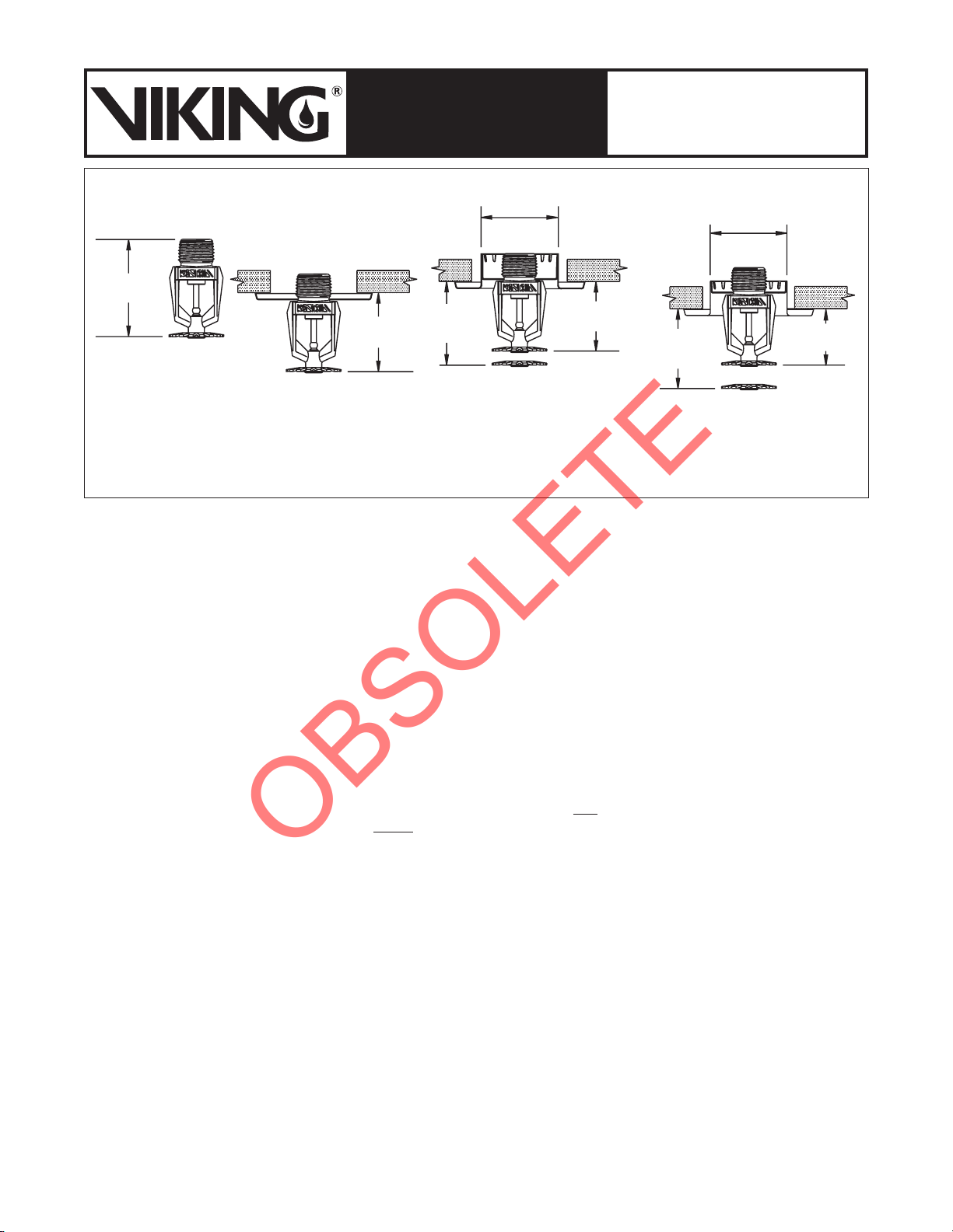
Special Response Pendent Sprinkler
with a Standard 1/8" (3,1 mm)
Surface-Mounted Escutcheon
Special Response Pendent Sprinkler
Installed with the Viking Microfast®
Model F-1 Adjustable Escutcheon Special Response Pendent Sprinkler
Installed with the Viking Micromatic®
Model E-1 Recessed Escutcheon
Ceiling Opening Size: 2-5/16" (59 mm) Minimum,
2-1/2" (64 mm) Maximum.
2-3/16”
(56 mm)
2-1/8”
(54 mm)
2” (51 mm)
Maximum
1-1/2” (32 mm)
Minimum
1-3/4” (45 mm)
Maximum
2-1/8”
(54 mm)
1” (25 mm)
Minimum
Special Response
Pendent Sprinkler
1-3/4”
(45 mm)
Figure 1