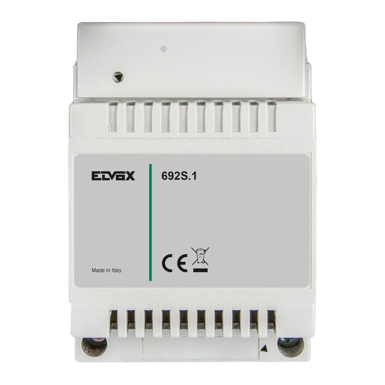
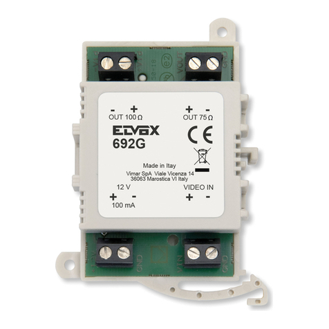
Vimar ELVOX 949S Assembly instructions

Manuale installatore - Installer guide
Art. 949S
Separatore Digibus a 4 e 8 cifre
Digibus separator with 4 and 8 digits

2
IT
DESCRIZIONE ART. 949S
L’art. 949S è un accessorio separatore da utilizzarsi negli impianti DIGIBUS sia a 4 che ad 8 cifre per creare:
• Unaprotezioneelettricasull’alimentazione.
• Unaseparazionefisicaperlalineadigitale(icomandivengonoritrasmessi)elafonica(normalmentescollegatadalrestodell’impianto)traungruppodicitofoni/
videocitofoniedilrestodell’impianto.
Alimentazione: 13.5 VDC
Potenza Max Assorbita: 0.5W
Ilseparatorevienecollegatonell’impiantotralatargaeilgruppodicitofono/videocitofonida“proteggere”.
E’possibileinstallareilseparatoreart.949Ssiaaparete,siasubarraDIN.(vediFig.1).
Detto accessorio viene utilizzato solamente per apparecchi interni muniti di decodifica a bordo.
Fig. 1
Tabella 1
LED - 1
LED - 2
PONTE
GENERATORE
DI CORRENTE
Morsetto Descrizione
5i Alimentazioned’ingressodelmontante(video)citofonico
4 Riferimento di Massa
1Digitaleversoi(video)citofoni
6Digitaleprovenientedalmontante(video)citofonico
3Fonicaversoi(video)citofoni
8Fonicaprovenientedalmontante(video)citofonico
5Alimentazioneversoi(video)citofoni
Tabella 2
Pulsanti - Led - Connettori
Pulsante S1 Per programmazioni
Pulsante S2 Per programmazioni
Led LED-1 Led per debug e programmazioni
Led LED-2 Led per debug e programmazioni
Ponticello GE Ponticello Generatore di Corrente
FUNZIONAMENTO
Allaprimaaccensione(assegnazioneIDapparecchiinterni)ilseparatore949Spermetteiltransitodeicomandia4oa8cifreconl’unionedellelineedifonica
perconversarefrainternoedesternoondefacilitarnelaprogrammazioneinterna.Unavoltaterminatal’assegnazionedituttigliIDinterniilseparatoreoivari
separatoriinseritinell’impiantodevonoessereprogrammaticomeutenteinizialeeutentefinalealorocollegati.Cosìprogrammaticonl’inviodiunachiamatache
risultaall’internoditalerange(utenteiniziale-utentefinale)siconnetteilrelèfonicadelseparatoreinmododapermetteresiailtransitodellachiamatachela
fonicaversolatargachiamante.Siprecisacheimonitordotatidigeneratoreinterno(serie6600)suonanoanchesenonsonoall’internodelrange(utenteiniziale
-utentefinale)mafonicamentenonsonocollegatiallatarga.Ilseparatoreunavoltaattivatosiresettaoperaltrachiamataoperfinechiamata.Ildispositivoripete
tuttiicomandidigitalichegliarrivanodalledueserialinellaserialeopposta.
Tabella 3. Tabella riassuntiva delle funzionalità
Ricezione da seriale a valle (morsetto 6), se programmati Utente Iniziale e Finale
COMANDO DIGIBUS Descrizione Funzionamento del 949S
CALL_TARGA
CALL_TARGA_TLC
CALL_TARGA_INT
CALL_TARGA_T_I
CALL_AUTOACC_TARGA
CALL_AUTOACC_TARGA_TLC
ChiamatadaunaTargaAudio-Videooppure
Autoaccensione
All’interno del proprio Range ATTIVAZIONE RELE’
All’esterno del proprio Range DISATTIVAZIONE RELE’
Comando di Reset DISATTIVAZIONE RELE’
Ricezione da seriale a monte (morsetto 1),anche se non programmati Utente Iniziale e Finale
COMANDO DIGIBUS Descrizione Funzionamento del 949S
ENTER_PRG Entratainprogrammazionediun(video)citofono ATTIVAZIONE RELE’
MEM_PRG Programmazioneavvenutadiun(video)citofono DISATTIVAZIONE RELE’
REC_NUMBER“*” Rispostadiun(video)citofonoadunachiamata
da targa
ATTIVAZIONE RELE’
“*”Comandononancoraoperativo
Il manuale istruzioni è scaricabile dal sito www.vimar.com
IT

3
Tabella 4. Significato dei Led
FUNZIONAMENTO DEI LED
Evento LED 1 LED 2
Ricezione dato seriale da morsetto 1 e trasmissione su morsetto 6 -Lampeggio
Ricezione dato seriale da morsetto 6 e trasmissione su morsetto 1 Lampeggio -
RicezionediunachiamatadaTargaall’internodelrangevalido AccesoFisso AccesoFisso
RicezioneComandodiResetduranteunaconversazionevalida Spegnimento Spegnimento
PROCEDURA DI PROGRAMMAZIONE
Programmazione Utente Iniziale e Finale
TenerepremutoilpulsanteS1per5secondicircafinoallampeggioripetutodelLED-2,rilasciaresuccessivamenteilpulsante,ripremerloemantenerlopremuto
finoall’entratainprogrammazione(accensionefissadelLED-2):aquestopuntorilasciareilpulsanteepremereiltastoperunatargaapulsantiocomporreda
targanumericailcodicedell’utenteiniziale(odalprogrammatoreart.950CoppureutilizzareilPCtramiteilsoftware“Analizer”conl’interfaccia6952/Aoppure
premereunqualsiasipulsantedauncitofonoconilnumerocorrispondenteall’utenteinizialedesiderato);dopoillampeggiodelLED-2,premereiltastoperuna
targaapulsantiocomporredatarganumericailnumerodell’utentefinale(odalprogrammatoreart.950CoppureutilizzareilPCtramiteilsoftware“Analyzer”
conl’interfaccia6952/Aoppurepremereunqualsiasipulsantedauncitofonoconilnumerocorrispondenteall’utentefinaledesiderato);aquestopuntoilLED-2
sispegneràperconfermarel’avvenutaprogrammazione.
PARAMETRI DI DEFAULT DEL 949S ALLA PRIMA ACCENSIONE
Utente Iniziale 0
UtenteFinale 0
Numero digit 8
Procedura di ripristino Parametri di Default
TenerepremutoilpulsanteS1per5secondicircafinoallampeggioripetutodelLED-2,rilasciaresuccessivamenteilpulsante,ripremerloemantenerlopremuto
finoall’entratainprogrammazione(accensionefissadelLED-2):aquestopuntorilasciareilpulsanteS1epremereilpulsanteS2finoallospegnimentodelLED-2.
INFORMAZIONE AGLI UTENTI AI SENSI DELLA DIRETTIVA 2002/96 (RAEE)
Alnedievitaredanniall’ambienteeallasaluteumanaoltrechediincorrereinsanzioniamministrative,l’apparecchiaturacheriportaquestosimbolodo-
vràesseresmaltitaseparatamentedairiutiurbaniovveroriconsegnataaldistributoreall’attodell’acquistodiunanuova.Laraccoltadell’apparecchiatura
contrassegnataconilsimbolodelbidonebarratodovràavvenireinconformitàalleistruzioniemanatedaglientiterritorialmenteprepostiallosmaltimento
deiriuti.Permaggioriinformazionicontattareilnumeroverde800-862307.
REGOLE DI INSTALLAZIONE.
L’installazionedeveessereeffettuataconl’osservanzadelledisposizioniregolantil’installazionedelmaterialeelettricoinvigorenelPaesedoveiprodottisono
installati.
CONFORMITÀ NORMATIVA.
DirettivaEMC
NormeEN61000-6-1,EN61000-6-3.
Ponticello GE (Generatore di Corrente)
Lalineadigitalecorrispondentealmorsetto1haungeneratoredicorrentechefornisce25mAperpermetterneilcorrettofunzionamentodelsistema.Secidoves-
seroesserepiù949SoppurepiùdispositividellaserieDigibuscollegatiinparallelosullastessalineadigitale(morsetto1-digitaleversoi(video)citofoni)solouno
diquestidevefornirelacorrentenecessaria.Perinterromperelagenerazionedellacorrentesul949S,tagliareilponticellovisibilenelforocontrassegnatoconGE.
IT

4
OPERATION
Whenswitchedonforthefirsttime(assigningIDofinternaldevices)theseparator949Sallowsthetransitof4-or8-digitcommandstogetherwiththevoicelines
betweeninternalandexternalinordertofacilitateinternalprogramming.OncealltheinternalIDshavebeenassigned,theseparatororthevariousseparators
insertedinthesystemmustbeprogrammedastheinitialuserandfinaluserconnectedtothem.Programmedinthiswaybysendingacallwhichiswithinthe
range(initialuser-finaluser),thevoicelinerelayoftheseparatorisconnectedsoastoallowthetransitofboththecallandthevoicelinetowardsthecalling
panel.Notethatthemonitorsequippedwithaninternalgenerator(series6600)ringeveniftheyarenotwithintherange(initialuser-finaluser)butasregards
thevoicelinetheyarenotconnectedtotheentrancepanel.Onceactivated,theseparatorisreseteitherforanothercallorattheendofthecall.Thedevice
repeatsallthedigitalcommandsthatitreceivesfromthetwoseriallinesintheoppositeserialline.
Table 3. Table summarising the functions
Reception from a downstream serial line (terminal 6), if Initial and Final User
DIGIBUS COMMAND Description Operation of the 949S
CALL_TARGA
CALL_TARGA_TLC
CALL_TARGA_INT
CALL_TARGA_T_I
CALL_AUTOACC_TARGA
CALL_AUTOACC_TARGA_TLC
CallfromanAudio-VideoPanelorSelf-start WithinitsownRange RELAY ACTIVATION’
OutsideitsownRange RELAY DEACTIVATION
Reset Command RELAY DEACTIVATION
Ricezione da seriale a monte (morsetto 1),anche se non programmati Utente Iniziale e Finale
DIGIBUS COMMAND Description Operation of the 949S
ENTER_PRG Enterprogrammingofa(video)interphone RELAY ACTIVATION’
MEM_PRG Completedprogrammingofa(video)interphone RELAY DEACTIVATION
REC_NUMBER“*” Replyofa(video)interphonetoacallfromtheen-
trance panel
RELAY DEACTIVATION
“*”Commandnotyetoperative
DESCRIPTION ART. 949S
Art.949SisaseparatoraccessoryforuseinDIGIBUSsystemswithboth4and8digitstocreate:
• Anelectricprotectiononthepowersupply.
• Aphysicalseparationforthedigitalline(thecommandsareretransmitted)andthevoiceline(normallydisconnectedfromtherestofthesystem)between
onegroupofinterphones/monitorsandtherestofthesystem.
Powersupply:13.5VDC
Max.AbsorbedPower:0.5W
Theseparatorisconnectedinthesystembetweentheentrancepanelandthegroupofinterphones/monitorstobe“protected”.Itispossibletoinstallthesep-
aratorart.949SeitheronthewalloronaDINrail.(seeFig.1).
This accessory is used only for internal devices with a decoder on board.
Table 1
LED - 1
LED - 2
CURRENT
GENERATOR
JUMPER
Terminal Description
5i Inputpowersupplyofthe(video)interphoneriser
4 Earth Reference
1Digitallineto(video)interphones
6Digitallinefromthe(video)interphoneriser
3Voicelineto(video)interphones
8Voicelinefromthe(video)interphoneriser
5Powersupplyto(video)interphones
Table 2
Pushbuttons-Led–Connectors
Pushbutton S1 Forprogramming
Pushbutton S2 Forprogramming
Led LED-1 Led for debug and programming
Led LED-2 Led for debug and programming
Jumper GE Current Generator Jumper
EN
The instruction manual is downloadable from the site www.vimar.com
Fig. 1
EN

5
Table 4. Meaning of the Led
LED OPERATION
Event LED 1 LED 2
Receptionofserialvaluefromterminal1andtransmissiononterminal6 - Flashinglight
Receptionofserialvaluefromterminal6andtransmissiononterminal1 Flashinglight -
Receptionofacallfromanentrancepanelwithinthevalidrange Steadylight Steadylight
ReceptionofResetCommandduringavalidconversation Off Off
GE Jumper (Current Generator)
Thedigitallinecorrespondingtoterminal1hasacurrentgeneratorwhichsupplies25mAtoallowthecorrectoperationofthesystem.Ifthereareseveral949S
devicesorseveraldevicesoftheDigibusseriesconnectedinparallelonthesamedigitalline(terminal1-digitallinetothe(video)phones)onlyoneofthesemust
supplythenecessarycurrent.Tostopcurrentgenerationonthe949S,cutthejumpervisibleintheholemarkedGE.
DEFAULT PARAMETERS OF THE 949S AT FIRST START
Initial User 0
FinalUser 0
Digit number 8
Procedure for restoring the Default Parameters
HolddownbuttonS1forabout5secondsuntilLED-2flashesrepeatedly,thenreleasethebutton,pressitagainandholditdownuntilyouenterprogramming
mode(LED-2litwithasteadylight):atthispointreleasethebuttonS1andpressthebuttonS2untilLED-2switchesoff.
INFORMATION FOR USERS UNDER DIRECTIVE 2002/96 (WEEE)
Inordertoavoiddamagetotheenvironmentandhumanhealthaswellasanyadministrativesanctions,anyappliancemarkedwiththissymbolmust
bedisposedofseparatelyfrommunicipalwaste,thatisitmustbereconsignedtothedealeruponpurchaseofanewone.Appliancesmarkedwiththe
crossedoutwheeliebinsymbolmustbecollectedinaccordancewiththeinstructionsissuedbythelocalauthoritiesresponsibleforwastedisposal.
INSTALLATION RULES.
InstallationshouldbecarriedoutobservingcurrentinstallationregulationsforelectricalsystemsintheCountrywheretheproductsareinstalled.
CONFORMITY.
EMCdirective
StandardsEN61000-6-1,EN61000-6-3.
PROGRAMMING PROCEDURE
Programming the Initial and Final User
HolddownbuttonS1forabout5secondsuntilLED-2flashesrepeatedly,thenreleasethebutton,pressitagainandholditdownuntilyouenterprogramming
mode(LED-2litwithasteadylight):atthispointreleasethebuttonandpressthekeyforapushbuttonpanelor,onanumericalpanel,composethecodeofthe
initialuser(orfromtheprogrammerart.950CorusethePCwith“Analizer”softwarewiththeinterface6952/Aorpressanybuttonfromaninterphonewiththe
numbercorrespondingtothedesiredinitialuser);aftertheflashingofLED-2,pressthekeyforapushbuttonpanelor,onanumericalpanel,composethecode
oftheinitialuser(orfromtheprogrammerart.950CorusethePCwith“Analyzer”softwarewiththeinterface6952/Aorpressanybuttonfromaninterphonewith
thenumbercorrespondingtothedesiredinitialuser);atthispointLED-2willswitchofftoconfirmthatprogramminghasbeencompleted.
EN

6
ID = 1 ID = 2
ID = 3ID = 4
ID = 5 ID = 6
ID = 7
ID = 8
R1
CH SF1F23 45+15O
4
R2
4
PRI
+I
-
S1M1V1V2M2
+
V
-
V
V1
V2
V3
V4
3
5
8
6
1
4
5i
+
V
-
V
V1
V2
V3
V4
10
5
4
3
2
1
8
7
9
6
M
12
V3
13
11
V2
V1
3
5
8
6
1
4
5i
13 54
3
5
8
6
1
4
5i
3
5
8
6
1
4
5i
3
1
4
10
R-CHHR+5F1SF23C4
219834567
TI+ I
BB BAA A
F1SCH
PRI
3F2 45
R2
15S1 0
4
R1
4
CN1
+
3
11
5
6
12
4
CN2
MONIT.
1
+D
CH
-
V3
+A
M
V2
V1
M
75ohm
+
3
11
5
6
12
4
CN2
MONIT.
1
+D
CH
-
75ohm
V3
+A
M
V2
V1
M
CN1
75ohm
75ohm
V3
13
V1
11
12
M
8
9
6
7
3
4
1
2
5
10
1
4
6
5
3
5
12
6
11
1
4
3
5
12
6
11
1
4
3
V3
13
V1
11
12
M
8
9
6
7
3
4
1
2
5
10
R1
R2
4
4
S1 15 0
PRI
F2CH SF1435
1V354 +
-
P
L
P
L
75ohm
75ohm
75ohm
75ohm
A1
+I
OFF
ON
+L
F2
F1
S
LA
LB
5
CH
M
V1
8
6
V2
V
M
4
3
1
D
LA
LB
ON
OFF
F2
+L
F1
S
+I
A
V1
M
V2
6
CH
8
1
3
4
5
V
M
D
R
R
Line2
Interc2
In/Out
Interc
POWERLINE
7
4
1
M
8
0
9
5
2
6
3
ELVOX
6
C
9
R
7
4
0
5
8
X
88888888
3
12
ELVOX
X
5
7
R
4
8
0C
9
6
2
88888888
13
Monitor
Art. 6344
Art. 6354
Monitor
Art.6624
Art.6724
B
Distributore
Distributor
Art.5556/004
Citofono
Phone
Art.6604/AU
Art.660D/AU
Art.6704/AU
Citofono
Phone
Art.6204
Montante monitor
Monitor cable riser
Alimentatore-Powersupply
Art. 6948
Rete
Mains
B- MonitorArt.6020+6204+6145,6023+6204+6145
A- TargaesternavideocontastieraserieDigibus
A1- TargaesternaaudiocontastieraserieDigibus
D- Modulosupplementare8A...,3A...
P- Pulsantesupplementareserratura
L- Serraturaelettrica12V~
Separatore
Separator
Art. 949S
Utente iniziale = 1
Initial user = 1
Utentefinale=2
Finaluser=2
B
Citofono
Phone
Art.6204
Citofono
Phone
Art.8878
Art.8878/1
Schema - Diagram N° SI583
B- MonitorArt.6020+6204+6145,6023+6204+6145
A- VideoexternalentrancepanelwithkeypadseriesDigibus
A1- AudioexternalentrancepanelwithkeypadseriesDigibus
D- Additionalmodule8A...,3A...
P- Lockadditionalpushbutton
L- Electriclock12V~
Alimentatore
Powersupply
Art. 6941
Rete
Mains
Separatore
Separator
Art. 949S
Utente iniziale = 3
Initial user = 3
Utente finale = 4
Finaluser=4
Distributore
Distributor
Art.5556/004
Montante citofoni
Interphone cable riser
Separatore-Separator
Art. 949S
Utenteiniziale=5-Initialuser=5
Utentefinale=6-Finaluser=6
Separatore-Separator
Art. 949S
Utenteiniziale=7
Initialuser=7
Utente finale = 8
Finaluser=8
Schema Digibus con centralino Art. 945B, montanti con targhe audio e video Art. 8943 e Art. 8946, separatore Art. 949S, monitor e citofoni.
Diagram of Digibus with switchboard Art. 945B, risers with audio and video panels Art. 8943 and type 8946, separator Art. 949S, monitors and interphones.
Centralino
Switchboard
Art. 945B
Alimentatore
Powersupply
Art.6942
SEZIONE MINIMA CONDUTTORI (in mm2)
MINIMUM CONDUCTOR SECTION (in mm2)
Morsetti
Terminals
Ø fino a 50 m
Ø up to 50 m
Ø fino a 100 m
Ø up to 100 m
Øfinoa200m
Øupto200m
4, 5, 9, 10 0,75mm
2
1 mm
2
1,5 mm
2
+,-,serratura•+,-,lock 1 mm
2
1,5 mm
2
2,5mm
2
Altri •Others 0,5 mm
2
0,75mm
2
1 mm
2
Video
Video
Cavocoassiale75Ohm(tipoRG59)oRG11adoppioisolamento
75Ohmcoaxialcable(typeRG59)orRG11doubleinsulation
EN IT

7
ID = 1 ID = 2
ID = 3ID = 4
ID = 5 ID = 6
ID = 7
ID = 8
DO CO
R1
CH SF1F2345+15O
4
R2
4
PRI
+I
-
S1M1V1V2M2
+
V
-
V
V1
V2
V3
V4
+L
M1
V2
+I
SR
V1
VL
F1
4
F2
CH
V
3
1
M
5
8
6
4
3
5
8
6
1
4
5i
+
V
-
V
V1
V2
V3
V4
10
5
4
3
2
1
8
7
9
6
M
12
V3
13
11
V2
V1
3
5
8
6
1
4
5i
13 54
3
5
8
6
1
4
5i
3
5
8
6
1
4
5i
3
1
4
10
R-CHHR+5F1SF23C4
219834567
TI+ I
BB BAA A
F1SCH
PRI
3F2 45
R2
15S1 0
4
R1
4
CN1
+
3
11
5
6
12
4
CN2
MONIT.
1
+D
CH
-
V3
+A
M
V2
V1
M
75ohm
+
3
11
5
6
12
4
CN2
MONIT.
1
+D
CH
-
75ohm
V3
+A
M
V2
V1
M
CN1
75ohm
75ohm
V3
13
V1
11
12
M
8
9
6
7
3
4
1
2
5
10
1
4
6
5
3
5
12
6
11
1
4
3
5
12
6
11
1
4
3
V3
13
V1
11
12
M
8
9
6
7
3
4
1
2
5
10
R1
R2
4
4
S1 15 0
PRI
F2CH SF1435
+L
M1
V2
+I
SR
V1
VL
F1
4
F2
CH
V
3
1
M
5
8
6
4
1V354 +
-
P
L
J1
DO
P
L
J1
CO
75ohm
75ohm
75ohm
75ohm
6
3
C
9
5
2
1
4
0
R
78
88888888
*
R
R
Line2
Interc2
In/Out
Interc
POWERLINE
7
4
1
M
8
0
9
5
2
6
3
*
88888888
8
7
R0
4
12
5
9
C
3
6
Monitor
Art. 6344
Art. 6354
Monitor
Art.6624
Art.6724
B
Distributore
Distributor
Art.5556/004
Citofono
Phone
Art.6604/AU
Art.660D/AU
Art.6704/AU
Citofono-Phone
Art.6204
Montante monitor
Monitor cable riser
Alimentatore
Powersupply
Art. 6948
Rete-Mains
Centralino
Switchboard
Art. 945B
B
Citofono-Phone
Art.6204
Citofono
Phone
Art.8878
Art.8878/1
Schema - Diagram N° SI582
Alimentatore
Powersupply
Art.6942
Alimentatore
Powersupply
Art. 6941
Separatore
Separator
Art. 949S
Utente iniziale = 3
Initial user = 3
Utente finale = 4
Finaluser=4
Distributore
Distributor
Art.5556/004
Montante citofoni
Interphone cable riser
Separatore-Separator
Art. 949S
Utente iniziale = 5
Initial user = 5
Utente finale = 6
Finaluser=6
Separatore
Separator
Art. 949S
Utenteiniziale=7
Initialuser=7
Utente finale = 8
Finaluser=8
Schema Digibus con centralino Art. 945B, montanti con targhe audio e video Art. 8844 e Art. 8847/C, separatore Art. 949S, monitor e citofoni.
Diagram of Digibus with switchboard Art. 945B, risers with audio and video panels Art. 8844 and Art. 8847/C, separator type 949S, monitors and interphones.
B- MonitorArt.6020+6204+6145,6023+6204+6145
D0-Targaesternavideocontasteracon tastiera serie Digibus
C0-Targaesternaaudiocontasteracon tastiera serie Digibus
P- Pulsantesupplementareserratura
L- Serraturaelettrica12V~
Rete
Mains
B- MonitorArt.6020+6204+6145,6023+6204+6145
D0-VideoexternalentrancepanelwithkeypadseriesDigibus
C0-AudioexternalentrancepanelwithkeypadseriesDigibus
P- Lockadditionalpushbutton
L- Electriclock12V~
SEZIONE MINIMA CONDUTTORI (in mm2)
MINIMUM CONDUCTOR SECTION (in mm2)
Morsetti
Terminals
Ø fino a 50 m
Ø up to 50 m
Ø fino a 100 m
Ø up to 100 m
Øfinoa200m
Øupto200m
4, 5, 9, 10 0,75mm
2
1 mm
2
1,5 mm
2
+,-,serratura•+,-,lock 1 mm
2
1,5 mm
2
2,5mm
2
Altri •Others 0,5 mm
2
0,75mm
2
1 mm
2
Video
Video
Cavocoassiale75Ohm(tipoRG59)oRG11adoppioisolamento
75Ohmcoaxialcable(typeRG59)orRG11doubleinsulation
Separatore-Separator
Art. 949S
Utente iniziale = 1
Initial user = 1
Utentefinale=2
Finaluser=2
ENIT

Vimar SpA: Viale Vicenza, 14
36063 Marostica VI - Italy
Tel. +39 0424 488 600 - Fax (Italia) 0424 488 188
Fax (Export) 0424 488 709
www.vimar.com
S6I.948.S00 03 1410
VIMAR - Marostica - Italy
Table of contents
Languages:
Other Vimar Water Filtration System manuals
Popular Water Filtration System manuals by other brands
Aquasana
Aquasana EQ-10000 installation instructions

Millipore
Millipore Milli-Q Direct 8 System user manual
AquaScape
AquaScape 82001 installation instructions
Spirotech
Spirotech SPIROVENT SUPERIOR S400 user manual

WET
WET GRO Installation, operation and maintenance manual
Pondmaster
Pondmaster Clearguard 2700 Care and operating instructions
