Vingtor Stentofon 1408001635 User manual

TECHNICAL
MANUAL
NR
XXXXXXXXXXXX
X
IP Desktop Video Station with
Touchscreen Display
A100K11664
TECHNICAL MANUAL

Contents
1General Information ............................................................................................ 3
1.1 Document Scope...................................................................................................................3
1.2 Document Log .......................................................................................................................3
1.3 Firmware Versions.................................................................................................................3
1.4 Hardware Versions................................................................................................................3
1.5 Related Documentation.........................................................................................................3
2Product Description............................................................................................ 4
2.1 Overview................................................................................................................................4
2.2 Features.................................................................................................................................5
3Operation & Configuration.................................................................................. 6
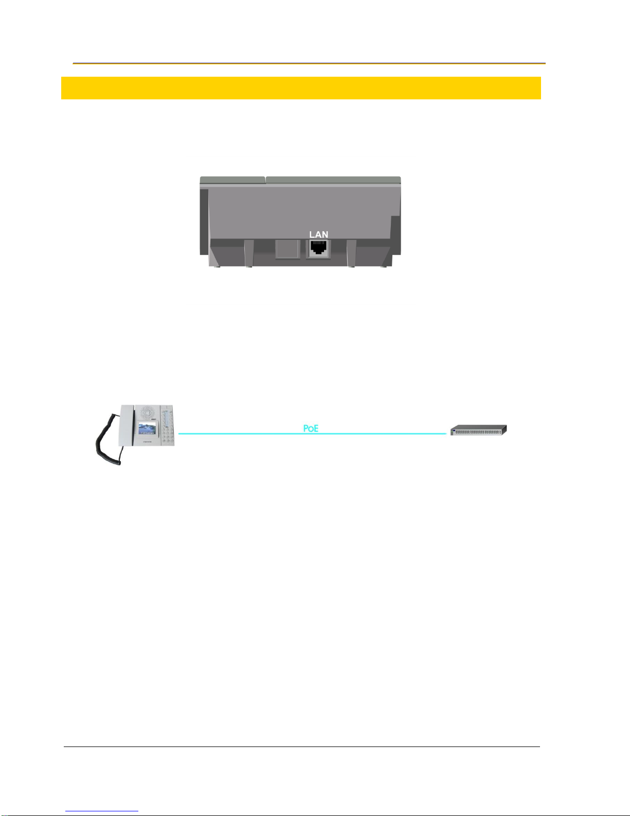
3.1 Connecting the IP Desktop Video Station.............................................................................6
3.2 Video Touchscreen Interface.................................................................................................6
3.2.1 General Workflow................................................................................................................................6
3.2.2 Touchscreen Calibration......................................................................................................................10
3.2.3 Factory Reset......................................................................................................................................10
3.3 Video Screen Web Interface..................................................................................................11
3.3.1 Login Procedure..................................................................................................................................11
3.3.2 User Settings.......................................................................................................................................12
3.3.3 User Interface......................................................................................................................................12
3.3.4 Camera Settings..................................................................................................................................15
3.3.5 Network Settings .................................................................................................................................17
3.3.6 System ................................................................................................................................................18
3.4 Updating the Video Screen....................................................................................................19
3.4.1 Updating the Firmware........................................................................................................................19
3.4.2 Updating the File System (User & Web Interface)...............................................................................19
3.5 IP Desktop Station Configuration ..........................................................................................20
3.5.1 Logging into the Web Interface............................................................................................................ 20
3.5.2 Station Mode and IP Settings..............................................................................................................22

A100K11664 IP Desktop Touchscreen Configuration & Operation 3
1 General Information
1.1 Document Scope
This document describes the configuration of the Vingtor-Stentofon IP Desktop Video station with a
3.5” LCD touchscreen display.
Product
Item Number
IP Desktop Video Station with Touchscreen Display & Handset
1408001635
1.2 Document Log
Version
Date
Author
Status/Comments
1.0
16.12.2013
Sc
Final draft
1.3
08.04.2014
Pl
Update IP Desktop Video Station user interface
1.4
04.09.2014
Pl
Update for Fw 1.10
1.5
17.12.2014
Eb
MTBF and response time of display added
1.6
09.05.2016
Pl
Update
2.0
22.06.2016
HKL
Revised with Turbine Video
1.3 Firmware Versions
Date
SubstationKit
VideoKit
Description / Function Expansion
05.07.2013
02.02.3.1
V1.3
First Prototype release
12.12.2013
02.04.1.12
V1.5
First Series release
04.05.2016
02.05.1.7
V2.2
Current version
1.4 Hardware Versions
Date
HW
Expansion
22.02.2013
0.1 A
First Prototypes
11.06.2013
1.0 B
Pre - Series
01.08.2013
1.1 C
Series
1.5 Related Documentation
Document no.
Title
A100K10788
IP Master Installation & Configuration Manual
A100K11559
Turbine Video Configuration Manual
A100K11377
IP Video Station Configuration Manual

4 IP Desktop Touchscreen Configuration & Operation A100K11664
2 Product Description
2.1 Overview
The Vingtor-Stentofon IP Desktop Video station is an intercom unit designed to be used in a
control room or similar type of environment. The station comes with a 3.5” LCD touchscreen
display and the capability of streaming video from an IP video camera using AlphaCom, Pulse, or
SIP station modes.
The desktop station can stream video from the following Vingtor-Stentofon Video stations:
Product Name
Item Number
Turbine Compact TCIV-2 IP Video Station
1008115020
Turbine Compact TCIV-3 IP Video Station
1008115030
Turbine Compact TCIV-6 IP Video Station
1008115060
Vandal Resistant IP Video Station
1401110100
Vandal Resistant IP Video Station
1401110200
It features a large high-contrast touchscreen with backlight which allows critical information about
connections to be shown clearly. The handset allows the user to switch from private to open
conversation in hands-free mode. Four touchscreen navigation keys and ten Direct Access Keys
(DAK) provide single-touch access to stations, group calls, audio monitoring, public address zones,
radio channels and/or the opening of doors and gates.
The station connects directly to the IP network, making it easy to deploy anywhere at any distance.
The built-in web server allows monitoring, configuration and software updates over the IP network,
hence maintaining a remotely located station is almost effortless. Designed for CCoIP®, the station
offers a set of critical communication features such as group call, call priority, and speaker volume
override. This enables the delivery of instant, efficient, and secure voice and data services in an IP
environment.

A100K11664 IP Desktop Touchscreen Configuration & Operation 5
2.2 Features
General
Designed to deliver CCoIP®–Critical Communication over IP
Call queue according to priority and time of call, 256 priority levels
Ten DAKs provide single-touch access to stations, group calls, audio monitoring,
public address zones, radio channels and phone lines.
Comes with handset for private conversations
Superb audio quality –high bandwidth codec, active noise cancellation, acoustic echo
cancellation and high output power amplifier
Remote software upgrade, configuration and monitoring
Video Touchscreen Hardware
3.5”TFT Touchscreen (embedded video, CCTV matrix not required)
High Contrast touchscreen with backlight for excellent readability
2-Level screen saver: High/Low lighted, Touchscreen off
Video Touchscreen Firmware (VideoKit)
Internal communication with IP desktop station via DIP protocol
1:1 Text display of the original desktop station LCD.
No special programming in AlphaCom required (special event handler scripts not
required)
Up to 80 IP cameras assignable to internal camera database in the video kit
accessible by web interface.
One camera is assignable to more than one station
One door station could be assigned to more IP cameras, switching through videos
Manual access to 80 IP cameras by touch screen to show videos at any time
Video display for all call events:
During incoming call
During outgoing call
During conversation
Text overlay with camera name or IP address, configurable position, color and font
while video is active
4 DAK key buttons on the touch screen as replacement for 4 DAK keys on IP Desk
Station

6 IP Desktop Touchscreen Configuration & Operation A100K11664
3 Operation & Configuration
3.1 Connecting the IP Desktop Video Station
There is a RJ45 port at the rear of the IP Desktop Video station for connecting via a network switch
to the LAN network.
To connect the IP Desktop Video station to the network:
Connect the LAN port of the IP Desktop Video station to a PoE network switch using a
network cable.
3.2 Video Touchscreen Interface
3.2.1 General Workflow
During startup the 3.5”LCD touchscreen displays the following splash screen information:
The IP connection type (DHCP, DHCP with fallback or Static)
The IP address of the video screen
The Netmask of the video screen
The Software version of the video screen
The Hardware version of the video screen

A100K11664 IP Desktop Touchscreen Configuration & Operation 7
Splash Screen
After startup the home screen is displayed.
Home Screen
The bar color on the display indicates the connection status:
Red indicates that no network connection can be established. If an Ethernet cable is
connected, the video screen should connect automatically during startup.
Yellow-Red flashing indicates that no connection to the server can be established. If
the server and the video screen are configured correctly, the connection will be
established automatically during startup. (This may take some time.)
Yellow indicates that the video screen is connected to the server.
Green indicates an active, incoming or outgoing call.
The three icons in the upper-right corner indicate:
Private Mode: The leftmost icon indicates that the station is in private mode. If the
station is not in private mode this icon is not visible.
Handset State: The icon in the middle indicates whether the handset is on-hook or
off-hook.
Volume: The rightmost icon indicates the current volume.
The volume of the ringtone can be adjusted by pressing the volume key located above the
touchscreen.

8 IP Desktop Touchscreen Configuration & Operation A100K11664
At the bottom of the touchscreen, there are four menu selection buttons. The menu options
available are dependent on how these buttons are configured on the AlphaCom server.
Tap anywhere on the screen and the Option Screen will be displayed for 10 seconds.
Option Screen
On the Option Screen there are four touch icons for executing the following functions:
Camera Select
The IP Desktop Video Station can allocate up to 80 cameras. They are listed in the
Camera Select screen with their labels, e.g. Main Entry, etc.
Camera Selection Screen

A100K11664 IP Desktop Touchscreen Configuration & Operation 9
Tap a label on the screen to show the camera stream for 60 seconds.
Tap the screen during this 60 seconds to stop the stream and revert back to the
Camera Select screen.
There are three navigation buttons on the right of the screen for scrolling up/down or
returning to the Option Screen
If access to the cameras have been configured to require passcode authentication (see section
3.3.4), the following passcode entry screen will be displayed:
Passcode Entry Screen
Enable/Disable Camera Switching
If more than one camera has been allocated to a remote station the touchscreen will
switch between the allocated cameras every 5 seconds. This feature can be
enabled/disabled here.
Enable/Disable Screensaver to avoid total switch-off
If this function is enabled, the screensaver does not switch off the display after a period
of inactivity. Only the backlight is dimmed.
Back to Home Screen
Tap this icon to revert back to the home screen.

10 IP Desktop Touchscreen Configuration & Operation A100K11664
3.2.2 Touchscreen Calibration
The touchscreen calibration display is activated by pressing and holding the screen during startup
when the splash screen is displayed or via the web interface under menu option System (see
section 3.3.6.).
Touch Calibration Screen
When the calibration screen is shown, tap the displayed cross and another cross will be displayed.
After tapping the second cross, the calibration process will be completed.
3.2.3 Factory Reset
A factory reset via touchscreen can be initiated by pressing and holding the options screen until a
confirmation dialog is displayed.
Factory Reset Confirmation Screen
Tap the checkmark icon to initiate a factory reset.
Tap the cross-mark icon to abort the factory reset.

A100K11664 IP Desktop Touchscreen Configuration & Operation 11
3.3 Video Screen Web Interface
3.3.1 Login Procedure
The video screen on the station has an integrated web interface which allows users to log
in via a standard web browser. In order to log into the video screen for the first time with
its default settings, proceed as follows:
1. Connect your PC to the network switch
2. Connect the LAN port of the IP Desktop to the network switch
3. Make sure your PC is set in the same IP address range as the video screen on the
station. The default IP address range is 169.254.1.xxx. Assign your PC an IP address
(e.g. 169.254.1.90 with net mask 255.255.255.0).
Note that the video screen has the default IP address 169.254.1.101 on delivery.
4. Open a web browser on your PC
5. Enter the default IP address 169.254.1.101 in the address bar.
6. Enter the username: admin
7. Enter the password: alphaadmin
The available menus options and relevant parameters are described in the following sections.

12 IP Desktop Touchscreen Configuration & Operation A100K11664
3.3.2 User Settings
Here you can change the username and password for access to the web interface.
Click User
User name : Enter a user name
Password : Enter a password
Repeat password : Type in the password again
Click Send settings
Click Submit settings to apply the settings.
3.3.3 User Interface
Here you can change the behavior of the user interface on the LCD screen.
Click User Interface

A100K11664 IP Desktop Touchscreen Configuration & Operation 13

14 IP Desktop Touchscreen Configuration & Operation A100K11664
Screensaver
Time until activation : Time until the touchscreen backlight is dimmed down
Time until shutdown : Time from the touchscreen backlight is dimmed down until
the touchscreen is switched off
Maximum brightness : Level of the maximum brightness of the touchscreen
backlight in normal operation (before the backlight is dimmed down)
Minimum brightness : Level of the minimum brightness of the touchscreen
backlight after it is dimmed down
Text overlay during video
Background
Coordinate x : Starting position on the x axis for the Background image
Coordinate y : Starting position on the y axis for the Background image
Width : Width of the background image
Height : Height of the background image
Color : background color
Text
Coordinate x : Start position on the x axis for the text overlay (relative to
Background image)
Coordinate y : Start position on the y axis for the text overlay (relative to
Background image)
Line spacing : The vertical distance between two lines
Font : Size of the font
Color : Color of the text
Hide after : Time until the text overlay fades out
Text on incoming call : Text displayed for incoming calls
Text on connected call : Text displayed for connected calls
Click Submit settings to apply the settings.

A100K11664 IP Desktop Touchscreen Configuration & Operation 15
3.3.4 Camera Settings
Here you can configure the camera settings for up to 80 cameras.
Click Cameras

16 IP Desktop Touchscreen Configuration & Operation A100K11664
Passcode
Passcode: Enter an up to 10 digit long numeric passcode to restrict access to the
cameras via the Camera Select screen on the station.
Camera Types
Camera Types Baudisch and AXIS are already predefined.
Name: The input fields on the left panel are for the camera names (e.g. TCIV for
Turbine Video). The name entered here will be added to the Camera Type select
box in the Camera Allocation section.
Path: The input fields on the right panel are for the path to the MJPG stream of the
camera in the form of [:<Port>][Path].
For TCIV-x Turbine Video stations the path is :8090/mjpg/video.mjpg
Camera Allocation
Name : Enter the name for the allocated camera (optional). This camera name is
displayed in the text overlay.
AlphaCom Node Number : Enter the Node Number of the Alphacom Server on
which the IP Desktop is registered (AlphaCom mode). Enter the value ‘0’ for both
Pulse and SIP mode.
AlphaCom Directory Number : Enter the Directory Number of the IP station with
the video camera (AlphaCom mode). Enter the value ‘0’ for both Pulse and SIP
mode.
SIP ID : Enter the Directory Number of the intercom unit which the camera is
associated with. (SIP/Pulse mode)
Camera IP : Enter the IP address of the station with the video camera.
Camera Type : Select the camera type based on the available camera types from
the dropdown box (e.g. TCIV, Baudisch, AXIS).
Camera User : Enter the username to access the camera stream (optional).
Camera Password : Enter the password to access the camera stream (optional).
Passcode Required : Check the box to enable or disable passcode authentication
to access this camera via the Camera Select screen on the station.
Allocation active? : Check the box to enable or disable the camera. This must be
enabled to be able to stream video from the camera.
Click Submit settings to apply the settings

A100K11664 IP Desktop Touchscreen Configuration & Operation 17
3.3.5 Network Settings
Here you can configure the network settings.
Click Network
IP settings
Connection type
DHCP :The IP Desktop Video Station automatically obtains its IP settings from a
DHCP server
DHCP with fallback : The IP Desktop Video Station automatically obtains its IP
settings from a DHCP server. If no DHCP server is available the IP Desktop Video
Station falls back to the IP address 10.10.10.10.
Manual : IP settings are set manually
IP address : IP address of the IP Desktop
Netmask : Subnet mask of the IP Desktop
Gateway : IP address of the router
DNS : IP address of the Name Server
Click Send settings

18 IP Desktop Touchscreen Configuration & Operation A100K11664
3.3.6 System
Here you can calibrate the touchscreen, do a factory reset, update the Desktop Video Station with
the latest firmware, etc.
Click System
Camera Allocation
Upload or download the camera allocation list.

A100K11664 IP Desktop Touchscreen Configuration & Operation 19
Settings
Upload or Download the settings (including the camera allocation).
Calibrate Touch Screen
Starts the touchscreen calibration.
Factory Reset
Resets the Desktop Video Station to factory settings.
Firmware Update
Updates the firmware.
3.4 Updating the Video Screen
3.4.1 Updating the Firmware
1. Log into the web interface of the video screen
2. Click System (see section 3.3.6)
3. Under category Firmware update click the Choose File button
4. Select the firmware file (The file has the extension .bin, e.g.
20160216PL_v11_FW_v21_StentofonIPDesktopVideo.bin)
5. Click the Upload button
6. When the upload is done the video screen will automatically reboot
3.4.2 Updating the File System (User & Web Interface)
To update the file system to a newer version, use the PC application IP Desktop Video –File
System Updater which comes with the software package:
1. Start the IP Desktop Video –File System Updater application by executing the
file IPDesktopVideoFSUpdater.exe
2. Enter the IP address of the video screen to open the login page
3. Enter the username (admin) and password (alphaadmin)

20 IP Desktop Touchscreen Configuration & Operation A100K11664
4. Click on the …button and navigate to the folder containing the new file system,
e.g. 20160216PL_FW_v21_RootFS_StentofonIPDesktopVideo
5. Select the folder of the new file system and click Ok
6. Click on the Erase File System button and wait for the station to reboot
7. After the reboot, click on Upload File System and wait for the process to complete
(this may take a few minutes)
8. When the update is completed, the station will reboot with the new file system.
Note that this feature is only available with firmware version 1.7 or later.
3.5 IP Desktop Station Configuration
For more detailed information on the configuration of the IP Desktop Station, see the manual
A100K10788 IP Master Stations Installation & Configuration.
3.5.1 Logging into the Web Interface
The IP Desktop has an integrated web interface which allows users to log in via a
standard web browser.
In order to login on an IP Desktop for the first time with its default settings, proceed as
follows:
1. Connect your PC with the network switch
2. Connect the LAN port of the IP Desktop to the network switch
3. Make sure your PC is set in the same IP address range as the IP Desktop. The
default IP address is in the range 169.254.1.xxx. Assign your PC an IP address
(e.g. 169.254.1.90, netmask 255.255.255.0).
The IP Desktop has the default IP address 169.254.1.100 on delivery.
Table of contents
Other Vingtor Stentofon IP Phone manuals