Vinten HD-VRC User manual

User Guide
Part No. V4063-0013
www.vinten.com
EN
HD-VRC Robotic Control System

Copyright © 2018
All rights reserved.
Original Instructions: English
All rights reserved throughout the world. No part of this publication may be stored in a retrieval system, transmitted, copied or reproduced in any
way, including, but not limited to, photocopy, photograph, magnetic or other record without the prior agreement and permission in writing of the Vitec
Group Plc.
Disclaimer
The information contained in this publication is believed to be correct at the time of printing. Vitec Production Solutions Ltd reserves the right to
make changes to the information or specications without obligation to notify any person of such revision or changes. Changes will be incorporated
in new versions of the publication.
We are making every eort to ensure that our publications are updated on a regular basis to reect changes to product specications and features.
Should this publication not contain information on the core functionality of your product, please let us know. You may be able to access the latest
revision of this publication from our website.
Vitec Production Solutions Ltd reserves the right to make changes to product design and functionality without notication.
Trademarks
All product trademarks and registered trademarks are the property of The Vitec Group Plc.
All other trademarks and registered trademarks are the property of their respective companies.
Published by:
Vitec Production Solutions Ltd
Supports Technical Publications Department
Email: [email protected]

Contents
Safety.....................................2
About this User Guide ...................... 3
Box Contents .............................. 4
Touch-screen Components and Connections ... 5
Joystick Panel Controls...................... 6
Joystick Panel Connections .................. 7
Joystick Panel Variants . . . . . . . . . . . . . . . . . . . . . . 8
HD-VRC Computer Components............... 9
HD-VRC Computer Connections.............. 10
Previous Version ......................... 10
Current Version .......................... 11
HD-VRC Computer Connections.............. 11
Connecting the HD-VRC System.............. 12
Control Connections ...................... 12
Camera Equipment Connections ............ 13
Connecting the HD-VRC System.............. 13
Video and Tally Connections ................ 14
Powering Up ............................ 15
Starting the HD-VRC System................. 15
Launching the VRC System Application ....... 15
Using the HD-VRC ....................... 15
Using the Joystick Control Panel . . . . . . . . . . 15
Using the HD-VRC System .................. 16
Joystick Control Panel Buttons .............. 16
Joystick Camera Controls ............... 18
Maintenance .............................. 20
Technical Specications .................... 21
General Notices ........................... 22

2
Safety
Important information on the safe installation and operation of
this product. Read this information before operating the product.
For your personal safety, read these instructions. Do not operate
the product if you do not understand how to use it safely. Save
these instructions for future reference.
Warning Symbols Used in these Instructions
Safety cautions are included in these instructions. These safety
instructions must be followed to avoid possible personal injury and
avoid possible damage to the product.
!
WARNING!
Where there is a risk of personal injury or injury to others,
comments appear supported by the warning triangle
symbol.
Where there is a risk of damage to the product,
associated equipment, process or surroundings,
comments appear supported by the word ‘CAUTION’.
ELECTRIC SHOCK
Where there is a risk of electric shock, comments appear
supported by the hazardous voltage warning triangle.
WARNING! Risk of electric shock. Always disconnect and
isolate the product from the power supply before attempting
any servicing or removing the covers. Always check cables
for signs of damage. Damaged cables can cause personal
injury and/or damage the equipment. It is the responsibility
of the local organisation to ensure that the product is
periodically checked for electrical safety in accordance with
local regulations.
!CAUTION! This product must be connected to a power
supply of the same voltage (V) and current (A) as indicated
on the product. Refer to the technical specications for the
product. Using alternative power sources will invalidate the
system EMC liability. All connections to other devices must
be made using shielded cables.
Intended Use
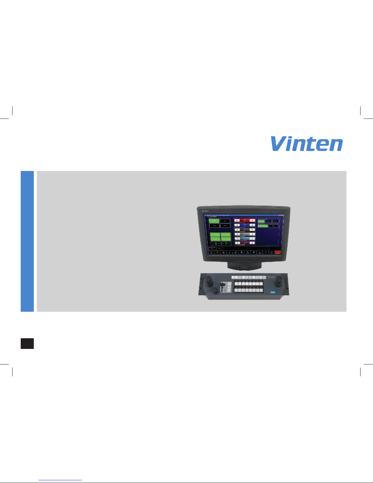
The HD-VRC robotic control system is designed to control compatible
robotic camera equipment and accessories. Camera operators can
remotely control movements of axes and other functions.
The HD-VRC is designed for use in TV studios and other applications
including houses of worship, conference facilities and auditoriums.
Electrical Connection
Operating Environment
!WARNING! Slots and openings are intended for ventilation
purposes to ensure reliable operation of the product and
protect it from overheating. Do not block or cover any slots
and openings. Protect the product from water, moisture
and dust. The presence of electricity near water can be
dangerous.
Important Safety Information
Mounting and Installation
!WARNING! Always ensure that all power and auxiliary
communications cables are routed so that they do not
present any danger to personnel. Take care when routing
cables in areas where robotic equipment is in use.
Cleaning
WARNING! Risk of electric shock. Always disconnect and
isolate the product from the power supply before cleaning.
Do not use solvent or oil-based cleaners, abrasives or wire
brushes. Clean with a dry lint free cloth.

3
Safety and About this User Guide
Maintenance
!WARNING! The tting of non-approved parts or accessories,
or the carrying out of non-approved alterations or servicing
can be dangerous and could aect the safety of the product.
It may also invalidate the terms and conditions of the product
warranty.
Safety when Working with Robotic Equipment
In normal operation remote-controlled equipment can move suddenly
and without warning. Since audible warnings are not suitable for use
within the studio environment, it is recommended that only trained
personnel be allowed to work in the active areas where remote
controlled robotic equipment is located.
The safe operating zone is a minimum of 1 m (3 ft).
Safety Notes for Operators
Operators must familiarise themselves with the working footprint of
the robotic equipment, including all installed payload items (lens,
zoom and focus controls, viewnder, prompter, etc.) to prevent
inadvertent collisions or injury to personnel.
If personnel are too close to robotic equipment that is about to move,
the operator should prevent the motion from starting or stop the
motion if it has started.
We strongly recommend that the operator veries visually that the
active area is clear of hazards and personnel, both before and during
remote operation.
This user guide covers the installation and basic operation of the
hardware components of the HD-VRC robotic control system.
For information on the conguration and operation of the VRC
application software, refer to the VRC System User Guide, part no.
V4063-4980.
About this User Guide

4
Box Contents
1HD-VRC computer
2Joystick control panel
3Panel power supply
4Touch-screen display
NI Serial cable
NI Power cable (x3)
NI User guide
1
2
3
NI - Not Illustrated
4

5
Touch-screen Components and Connections
5
1
2
6 74
1Touch-screen interface
2Adjustable stand
3Power button
4USB (down)
5USB (up)
6Power socket
7D-SUB (VGA) socket
3

6
Joystick Panel Controls
123
4
5
76
1X/Y/Height joystick control*
2CCU black level control*
3CCU iris control*
4Function buttons*
5“on air” indicator
10
8
9
6Pan/Tilt/Zoom joystick control
7Camera selection buttons and tally indicators (x16)
8Camera control buttons (Cut/Fade/Stop)
9Fade time control
10 Focus control
*Control and button functions
are not present on all panel
models. See....

7
Joystick Panel Connections
1
2
3
4
5
6
7
8
9
1Tally socket
2Vision switcher socket (serial)
3Auxiliary socket
4Touch-screen socket
5PC socket
6HCU socket
7Vision switcher socket (parallel)
8Auxiliary relays socket
9Power socket (12V DC)

8
Joystick Panel Variants
Name Part No. X/Y/Z (height)
Control
Camera
buttons
CCU
controls
Focus control
position
VRC-SJP focus LHS V3976-0013 16 Left
VRC-SJP focus RHS V3976-0017 16 Right
VRC-DJP focus LHS V3976-0014 16 Left
VRC-DJP focus RHS V3976-0018 16 Right
VRC-SJP+CCU focus LHS V3976-0015 16 Left
VRC-SJP+CCU focus RHS V3976-0019 16 Right
VRC-DJP+CCU focus LHS V3976-0016 16 Left
VRC-DJP+CCU focus RHS V3976-0020 16 Right
MJP+CCU V4008-0003 12 N/A
Dierent variant models of the joystick control panel are available to
match the requirements of the user and the complexity of the VRC
system installation.
Panels are available with or without pedestal controls (X/Y/Z) and
CCU controls. There are also options for left or right mounting of the
focus control.

9
HD-VRC Computer Components
1HDD indicator
2Power indicator
3Lockable DVD drive access panel
1
2
3

10
HD-VRC Computer Connections
1 2 3 4
5 6 7 8
10
5Component video sockets
6SDI (IN/OUT) video sockets
7PS2 keyboard socket
8Ethernet socket
9VGA socket (to touch-screen)
10 AC power switch
1RS422 serial sockets (COM3&4)
2USB sockets (x2)
3RS232 serial sockets (COM1&2)
4AC power socket
Previous Version
9

11
HD-VRC Computer Connections
Current Version
1 2 3 4 5
6 7 8 9 10 11
5RS232 serial sockets (COM1&2)
6HDMI socket (Video capture)
7USB sockets (x2)
8SDI socket (Video capture)
9VGA socket (to touch-screen)
10 Ethernet socket
11 USB sockets (x2)
1AC power socket
2AC power switch
3DVI socket
4RS422 serial sockets (COM3&4)

12
Connecting the HD-VRC System
Control Connections
The basic HD-VRC control system consists of the HD-VRC computer, touch-screen monitor and joystick control panel connected together. Remote
camera equipment is connected using standard Ethernet connections, using a powered Ethernet switch to expand the number of connections
available to suit your system requirements.
In larger systems, several VRC computer control systems (including μVRC) may be connected together using Ethernet connections.

13
Connecting the HD-VRC System
Camera Equipment Connections
Remote camera equipment, including robotic pan and tilt heads, PTZ heads*, pedestals and lens drives can all be connected and controlled by
the HD-VRC control system**. All camera equipment must be connected to the same Ethernet network, easily expanded at any time to match your
systems requirements.
* To connect PTZ heads, an additional license is required. For more information refer to the VRC System User Guide, part no. V4063-4980.
** The HD-VRC must be connected to a control panel variant capable of controlling all functions of the camera equipment required in the system.

14
Connecting the HD-VRC System
Video and Tally Connections
In a typical HD-VRC control system installation, a video switcher and tally interface are also connected to provide live on-air camera feeds for
monitoring purposes and thumbnail video capture.
For more information about connecting devices, refer to the documentation supplied with your video switcher or tally interface.

15
Powering Up
When all connections in the HD-VRC system have been made, the
HD-VRC touch-screen, computer and joystick control panel can be
powered up.
1. To power up the touch-screen, depress the power button
recessed under the front screen bezzel.
Using the HD-VRC
The HD-VRC user interface consists of a touch-screen display and a
joystick control panel, through which all functions and operations can
be utilised.
Using the Joystick Control Panel
The joystick control panel enables you to select and control
connected robotic cameras. Additional keys are available to select
cameras and other useful functions.
Launching the VRC System Application
When the HD-VRC computer has booted up, the VRC system
application must be installed, congured and launched before robotic
cameras can be controlled.
For more information on the VRC system
application, refer to the VRC System User
Guide, part no. V4063-4980.
Starting the HD-VRC System
3. The joystick control panel powers up automatically when DC
power is applied.
2. To power up the HD-VRC computer, depress the AC power switch
on the rear connection panel.

16
Using the HD-VRC System
Joystick Control Panel Buttons
The joystick control panel has a selection of useful short cut buttons which duplicate features and functions available on the touch-screen display.
The buttons provide quick access to functions when the operator is using the panel to control cameras.
This guide details the use of all control panel variations, and therefore some functions may not be present on your control panel. If a button or
control described in the text or illustrations is not present on your control panel, then your model does not support that function. It is also possible
that during installation the functionality of the system function buttons has been customised, aecting functions available and their precise location
on the panel.
Using the HD-VRC System

17
Motion Control Buttons 1 Cut Moves to the next selected shot in the fastest possible time
2 Fade Moves to the next selected shot in the selected time
3Stop Stops all camera movement
Camera Buttons 4 Camera Selection Selects the camera to control (up to 16 selections)
Function Buttons 5 Wash/wipe (Optional) - activates a lens wiper on an outside camera
6 Joystick enable Enables X/Y pedestal movement (prevents accidental movement when o)
7 Pan follow When enabled, controlling the Y axis causes the pedestal to travel forwards and
backwards in the direction that the camera is pointing
8 X4 Disables zoom proportional mode - with X4 enabled, pan and tilt movements are
more sensitive when zoomed in
9 Panel disable Locks all other controls on the panel to prevent accidental operation
Indications 10 On air Indicates that the panel is controlling live cameras when illuminated
11 Tally indicators Indicators show which camera’s video signal is currently live on air
Using the HD-VRC System

18
Joystick Camera Controls
The joystick panel provides the best way to smoothly control camera movement and adjustments. Many control functions can be reversed in the
VRC application conguration to suit a users preferences.
Robotic Pedestal, Head and Camera Controls
Using the HD-VRC System
Table of contents
Other Vinten Control System manuals