VISICO Elfin Series User manual

VL II PLUS
USER GUIDE
Elfin Series
Main Feature of VL II PlUS Elfin Series
Output Control range full to 1/32(5 stops)
radio transmitter
Lightweight, Compact and Easy to Operate
Clear Digital Display to show accurately the power level
CMOS Chip Technology
Precision light output
Fast Recycling time and Flash Duration
Overheating warning function
Build-in radio receiver, match with VISICO
Perfect for online store, photography studio,
and shutterbugs
Distributor
Facebook Mobile Website
Please read these instructions carefully
before using it. Thank you.

Thanks for selecting this compact flash unit. Please read these instructions
carefully and keep them handy for your reference.
The VL Series is a powerful, self contained AC powered, electronic
flash unit.
This Flash provides flexibility in positioning and ease of use.
Please ensure that you are completely familiar with the operations and features
of your new flash before using it.
Safety Notes
When using this photo flash unit, basic safety precautions should always be
followed, including the following:
1. Read and understand all instructions before using.
2. Close supervision is necessary when any appliance is used by or near children.
Do not leave appliance unattended while in use.
3. Care must be taken as burns can occur from touching hot parts.
4. Do not operate appliance with a damaged cord or if the appliance has been
dropped or damaged – until it has been examined by a qualified technician.
5. Position the cord so that it will not be tripped over, pulled, or contact hot
surfaces.
6. If an extension cord is necessary, a cord with a current rating at least equal to
that of the appliance should be used. Cords rated for less amperage than the
appliance may overheat.
7. Always unplug appliance from electrical outlet before cleaning and servicing
and when not in use. Never yank cord to pull plug from outlet. Grasp plug and
pull to disconnect.
8. Let appliance cool completely before putting away. Loop cord loosely around
appliance when storing.
9. To reduce the risk of electric shock, do not immerse this appliance in water or
other liquids.
Table of Contents
Description
Safety Notes
Content of carton
Preparing Your Flash For Use
Power supply connection
Light Holder with umbrella Hole
Operating the modeling lamp
Triggering the flash
Audible Beep Settings
Flash Output
Changing the Flash Tube
Changing the fuses
Overheating Protection
Flash Capacitor Preventative Maintenance
Specifications
Page
VL II PLUS
................................................................................................ 02
03
.....................................................................................
03
04
......................................................................
...........................................................
........................................................ 05
05
05
.............................................................
..................................................................................
........................................................................... 11
............................................................................................... 11
..................................................................... 12
................................................................................. 13
......................................................................... 13
............................... 13
............................................................................................. 14

11. To reduce the risk of electric shock, do not
disassemble this appliance, but take it to a qualified
technician when service or repair work is required.
Incorrect reassembly can cause electric shock when the appliance
is used subsequently.
12. The use of an accessory attachment not recommended by
the manufacturer may cause a risk of fire, electric shock, or injury to persons.
13. Connect this appliance to a grounded outlet.
14. Disconnect this unit from its source of supply before replacing the
modeling lamp.
15. This appliance has a polarized plug. To reduce the risk of electric shock,
this plug is intended to fit in a polarized outlet only one way. If the plug
does not fit fully in the outlet, reverse the plug. If it still does not fit,
contact a qualified electrician. Do not modify the plug in any way.
Content of carton
110V-120V or 220-240V Flash unit with flash tube
Standard Reflector(with or without standard reflector)
Protective cover
Power cable
4.5V Sync. Cable
User Guide
1/ Preparing Your Flash For Use
Ensure the flash is switched off and disconnected from mains supply.
To remove plastic protective cap, push the latch knob back towards the
rear of the unit and rotate the plastic protective cap counterclockwise.
Install the reflector where the protective cap was before. Align the three pegs
on the reflector with the three slots, press the reflector in and rotate clockwise until
it locks in place.
Fig. 1 Fig. 2 Fig. 3
Note: Take care when fitting or removing reflectors or softboxes not to damage
the flash tube assembly. The flash tube is very delicate;avoid unnecessary handling
of the flash tube. Always switch off and disconnect from the main supply before
fitting and changing reflectors.
Ensure the flash is switched off and disconnected from mains supply.
Use softbox no larger than 60x90cm size or octagon 80cm. Use beauty dish no
larger than Dia 460mm size.
2/ Power supply connection
Use only the mains leads supplied to connect to the main power.
Before plugging the power cord into the wall socket, make certain that the power
switch is set to the OFF
Fig. 4
A:LED Display
B:Test Button
C:Ready Flash Beeper Button ON/OFF
D:Photocell(Slave) Button ON/OFF
E: Photocell(Slave)
F:Modelling Lamp ON/OFF
G: Flash Power Regulator
H: Umbrella Holder
I:Power Cable Input
J:Sync Cord Input
K:Main Power Switch
L:Fuse
VL II PLUS

3/ Light Holder with umbrella Hole
An umbrella with a handle diameter of 8-10mm can be firmly
secured in the umbrella holder. Do not over tighten the screw of the
umbrella holder to avoid squashing the shaft of the umbrella.
4/ Operating the modelling lamp
To turn the modelling lamp 'ON' and 'OFF', press the touch button F (fig.1).
5/ Triggering the Flash
5-1 TEST Button
The simplest way to trigger the flash is to press the TEST button B(Fig.1)
This is useful when you need to discharge the power built up in the flash
unit. For example just before replacing the flash tube(more on that later).
5-2 Sync Connection
The sync jack J(Fig.1) on the flash may be used for direct connection to a camera
set to "X" synchronization. A radio slave receiver may also be plugged into the
socket.
5-3 Photocell
The photocell is located behind the red transparent cover on the top and at the back
of the unit.
It enables the unit to be triggered from another flash unit, IR remote trigger or small
on-camera flash. Switch the photocell ON or OFF using the switch D (fig.1) on the
control panel. The photocell is ON when the Green LED Number 1 is lit. To disable
press switch D (fig.1) again until LED is off.
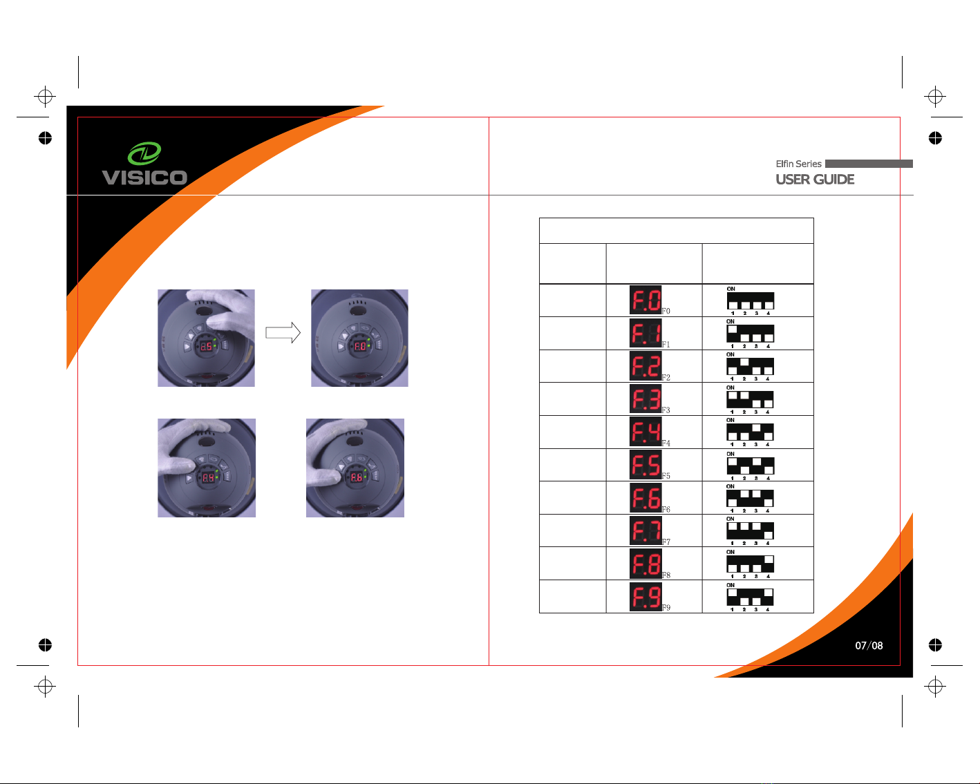
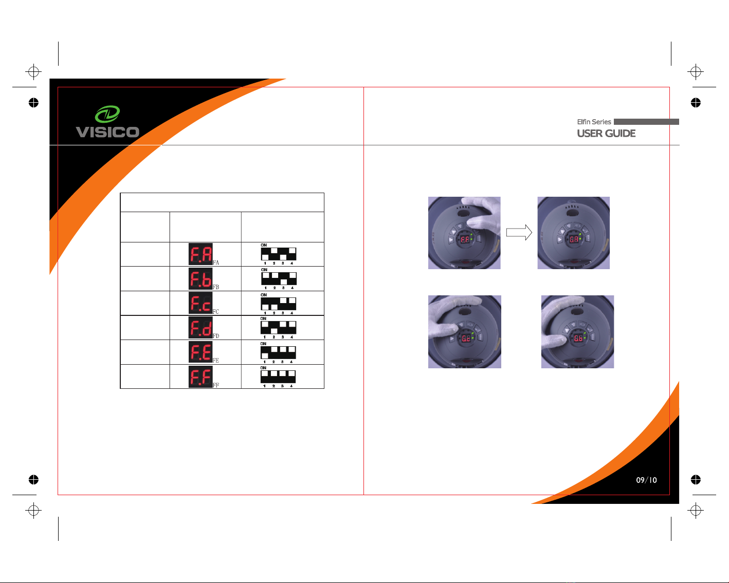
The numbers of preflashes is variable from 1 time, 2 times, 3 times, 4 times, 5 times,
6 times, and 7 times. Press SLAVE button D (fig.1) 4 seconds to access preflashes
setup page “Cx ”.
Press slave button 4 seconds to get access to preflashes setup page “Cx”
Press 4s
Press up or down button to adjust preflashes from 1 to 7.
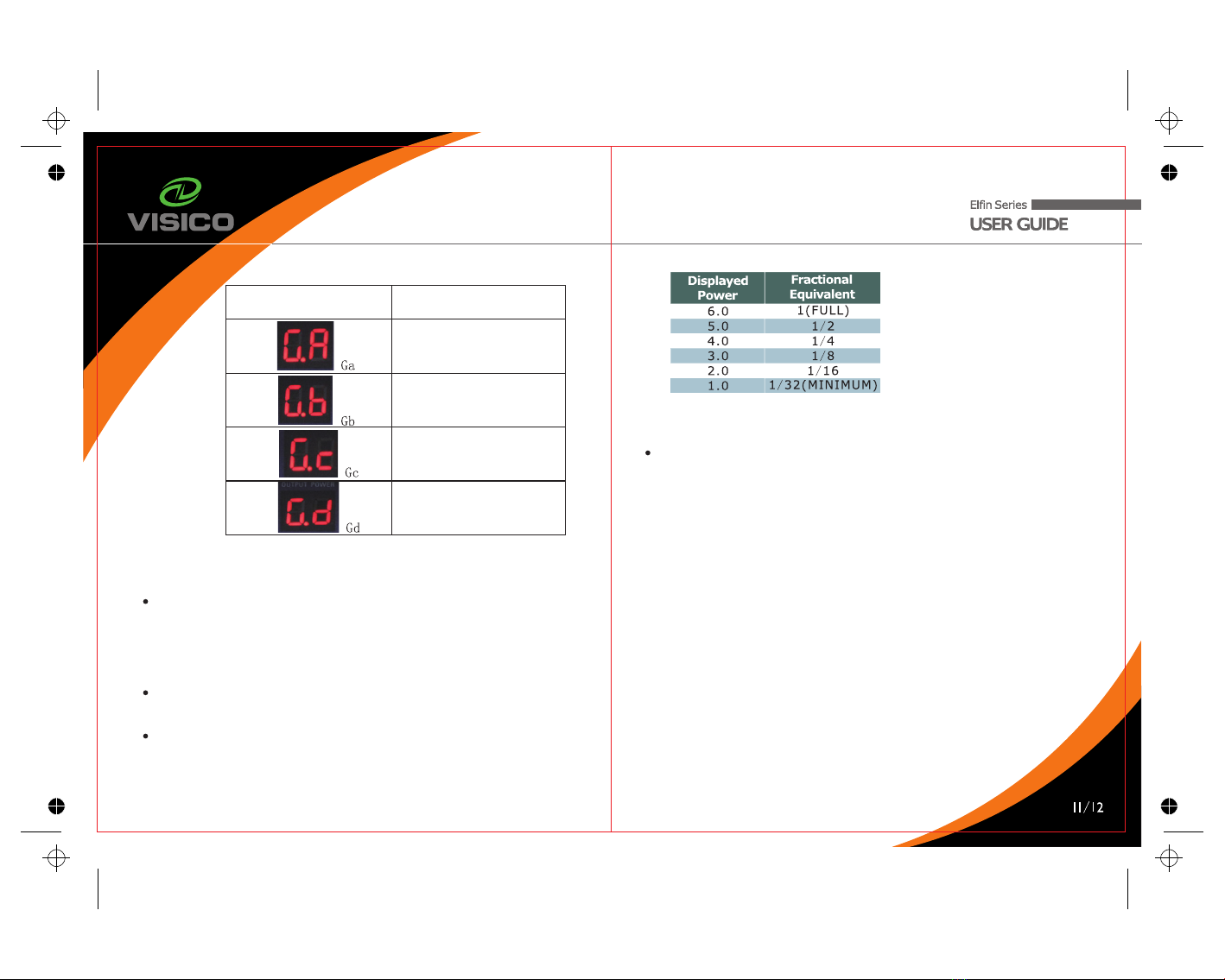
“C0” is automatic recognition mode. Use camera flash and release a test exposure.
The photocell detects the number of flashes the camera released and memorizes the
value automatically.
If you have selected "C1", the unit will autoflash immediately when another flash is
activated in the same area.
If you have selected "C2" the unit will autoflash on the second flash detected by the
photocell.
If you have selected "C3", the unit will autoflash on the third flash detected by the
photocell.
If you have selected "C4", the unit will autoflash on the fourth flash detected by the
photocell.
If you have selected "C5", the unit will autoflash on the fifth flash detected by the
photocell.
If you have selected "C6", the unit will autoflash on the sixth flash detected by the
photocell.
If you have selected "C7", the unit will autoflash on the seventh flash detected
by the photocell.
NOTE: The photocell is very sensitive but some experimentation with positioning
may be necessary to ensure a reliable trigger, particularly if the cell is not in
the direct line of sight of the triggering flash unit. Avoid directly illuminating
the photocell from a continuous light source (such as ceiling lights or
windows) since this can prevent correct operation. Very high ceilings
can also affect the operation of the photocell.
VL II PLUS

5-4 2.4G Build-in Radio Receiver
When VL studio flash is at menu “Cx”, press slave button once
to enter into radio channel setup menu “Fx”.
Press once
There are totally 16 different channels for your choice from F0 to FF. Press UP or
DOWN button to select proper receiver channel.
To use 2.4G radio receiver function, you need to purchase separately a VISICO
radio transmitter (VC-816TX, VC-16TX, VC-801TX,VC-818TX, VC-818S). Only
when studio flash and the transmitters are at the same channel, the studio flash
can be triggered.
The following tables show how to match codes between radio transmitter and
receiver correctly.
Radio Receiver and transmitter frequency Setup
Channel code Corresponding code on
VL Studio Flash
Corresponding setup on
Radio Transmitter
0
1
2
3
4
5
6
7
8
9
VL II PLUS

Radio Receiver and transmitter frequency Setup
Channel code Corresponding code on
VL Studio Flash
Corresponding setup on
Radio Transmitter
10
11
12
13
14
15
VL II PLUS
On the radio transmitter, the code from left to right is 1,2,3,4.
When push the button to “ON”, every code represent a value, channel 1
represent digit 1, channel 2 represents digit 2, channel 3 represent digit 4,
channel 4 represent digit 8. When push the button to “number side”, the digit
is 0. You can calculate the total value according to the key's state.
For example, when all the 4 buttons are set to “ON” side, the total value is
1+2+4+8=15. “15” is the channel code.
5-5 Group function
When VL studio flash at “Fx” menu, pressing slave button once to access
to group setup menu “Gx”.
Press once
There are in total 4 groups for your choice from GA, Gb, Gc to Gd. Press UP or
DOWN button to select proper receiver channel.
To use group function, please purchase use a VISICO transmitter VC-801TX,
VC-818TX or VC-818S (not include). Only when the studio flashes and transmitter
are at the same channel and group ,flash output and modeling lamp can be controlled.
The following picture shows how to set the same groups between flash light and
remote controller.

VL II PLUS
Corresponding Group on
VL Studio Flash
Corresponding group on
radio transmitter VC-801TX
Group 1
Group 2
Group 3
Group 4
Press the slave button 8 seconds, or wait 20 seconds to quit to
output power page.
6/ Audible Beep Settings
Push the Beeper Button C(Fig.1) to 'ON' to give a short beep when the unit is
ready to fire, to provide an audible “Ready confirmation”.
NOTE: Turning the switch C (Fig.1) OFF will allow the modelling lamp to turn off
automatically while the flash is fired.
7/ Flash Output
The flash power output is variable over a 5 f-stops range (6 f-stops) from full to
1/32 in 1/10 f-stop increments using two power regulator adjustment buttons G
(Fig.1) on the rear panel.
The control has a minimum setting of 1.0 and a maximum setting of 6.0.
Pressing the regulator adjustment buttons G (Fig.1) will changes the value by
0.1 f-stop (to give you a total of 50 values. E.g. If the current value shown is
5.6 then to reduce the power by 1 f-stop just reduce it to 4.6. The following
table shows the whole decimal numbers and equivalent fractional power ration:
8/ Changing the Flash Tube
8-1 Discharge the Flash Unit
The charge in the flash unit must be discharged before removing the flash tube.
To discharge the Flash unit:
1. Make sure the Flash unit is ON.
2. Push the red "TEST" button on the rear panel of the Flash.
3. Immediately turn off the power switch on the rear panel of the Flash. Do not allow
more than 1/2 second between pressing the "TEST" button and the power switch.
4. Remove power cord from power source before removing the flashtube. It is
recommended to wait at least 30 minutes before touching/removing the flash tube.
Note: Use white cotton gloves or a clean cloth or glove to prevent fingers from
touching the flash tube.
8-2 Remove Old Flash Tube
First, remove the reflector. With needle-nose pliers, loose the wire that wrapped
around metal clips. Using white cotton gloves or a clean cloth, grip the base of the
flash tube on each side. Carefully pull the flash tube from the flash unit.
8-3 Install New Flash Tube
Safety Note: Make sure the power switch is OFF and the power cord is removed
from the source.
1. Align the pins on the flash tube with the pin receptacles. Push the pins into the
receptacles using firm, even pressure at the base of the flash tube (Fig.5). Place
the tube in between the metal clip (Fig6).
2. Pull out the wire,wrap it around the flash tube for several circles. With
needle-nose pliers, gently pull the wire upward until tighten (Fig.7).
Wrap the rest wire around the metal clip and press tightly. (Fig.8)

12/ Specifications
Fig. 5 Fig. 6
Fig. 7 Fig. 8
9/ Changing the fuses
A 4A fuse is mounted at the bottom of the flash unit.
Disconnect the power supply before changing the fuse. Never replace with
a fuse of a different type or rating. A spare 4A fuse is fitted in the fuse holder L
(Fig.1).
Use a small screwdriver to release fuse cover, remove the old fuse, place the
new fuse in the slot, then replace the fuse holder.
10/ Overheating Protection
After a long shooting session at high output, the recycling time of the flash will
increase automatically until the flash cools down to a safe level and will start
working normally again.
VL II PLUS
11/ Flash Capacitor Preventative Maintenance
One of the most important components of an electronic flash are the capacitors.
Following the preventative maintenance below will increase the life and the
reliability of your flash.
If the unit is left unused for a few months or predominantly used at low power
settings it is recommended that the power be increased to maximum and the
unit left switched on (modeling lamp OFF) occasionally for at least 30 minutes
to help preserve the life of the capacitors.
Flash Specifications
Power Output
GN (2m, ISO 100)
1/60 Reflector SF-610
VL-100 II
PLUS
VL-150 II
PLUS
VL-200 II
PLUS
VL-300 II
PLUS
VL-400 II
PLUS
100W 150W 200W 300W 400W
30 43 50 60 70
Output Control range Full to 1/32 Stepless
Recycling Time to Full
220V-240V/50Hz 0.3~1.2s 0.4~1.3s 0.5~1.8s 0.6~2.0s
0.8~2.3s
Recycling Time to Full
110V-120V/60Hz 0.8~1.5s 0.8~1.8s 0.8~2.1s 0.8~2.5s 1~3.0s
Flash Duration 1/800th ~ 1/1200th
Modelling Lamp Output 5W LED
Illuminance of 5W LED
(with reflector)
Color temperature of
5W LED
Triggering Method
color temperature of
flash tube
Flash Tube
Triggering Voltage
9000Lux/ 0.5m
4000K±200K
Slave Sensor / Sync Cable / Test Button/Build-in 2.4GHz radio receiver
5600K±200°
"plug-in" Tube (user replaceable)
5V Low Voltage Trigger
Fuse
Digital display
Bowens adapter
Weight
4A
Overheating warning
Power Source
Accessories Included
Dimensions (cm)
Yes
Yes
Yes
AC 190-240V 50Hz or AC 100-130V 60Hz
Reflector, Power Cord(4m), Sync Cord(4m), User Guide
0.75kg 0.85kg 0.9kg 1.0kg 1.1kg
20x12x12 (without reflector)
* Test by SEKONIC L-758DR Light meter
*Due to our policy of constant product improvement
we reserve the right to change equipment
specifications without notice.
This manual suits for next models
6
Table of contents
Other VISICO Lighting Equipment manuals
Popular Lighting Equipment manuals by other brands

Lumisave
Lumisave SL760 Series Installation and Product Manual

AS LED Lighting
AS LED Lighting MidPower 050037 Mounting instructions

Kaiser Fototechnik
Kaiser Fototechnik RB 5970 UV operating instructions

Exterrain
Exterrain RAVEN560 user manual

ADB Safegate
ADB Safegate RELIANCE user manual

JONATHAN Y
JONATHAN Y JYL4004A Install

BEGA
BEGA 70 524 Instructions for use

Star Headlight & Lantern
Star Headlight & Lantern PHAZER ESSENTIAL Series Installation, Basic Programming, and Operation Manual

Golight
Golight 2020 Instruction guide

NENKO
NENKO 25001477 quick start guide

EuroLite
EuroLite 51937105 user manual

Zodiac
Zodiac iAquaLink 2.0 installation manual