manuals.online logo
Brands
  1. Home
  2. •
  3. Brands
  4. •
  5. Champlain
  6. •
  7. Lighting Equipment
  8. •
  9. Champlain ACM-101AS User manual

Champlain ACM-101AS User manual

2”
IMPORTANT
ACM-101AS; ACM-101AS-ST
Hardware • Jeu de pièces
Champlain Plastics Inc.
87 Pillsbury Road
Rouses Point, NY 12979
(INS-1101AS-rev5)
P1 P2 P3
x 1
P2A
x 1x 2 x 2
P4 x 1
x 4
x 8 x 8 x 8 x 4 x 4
x 8 x 8 x 4
!
" # $ % & x 4
'
()*
ÉTAPE 6
Il est nécessaire d'être deux
personnes pour installer l'échelle
dans la piscine. S'assurer que
l'espace entre la paroi intérieure
de la piscine et l'échelle soit de 2"
et que chaque muret et chaque
marche soient bien fixés à
l'échelle.
AVERTISSEMENT :
L'espace entre la paroi intérieure
de la piscine et l'échelle ne doit
pas excéder 2" afin d'éviter
qu'une personne n'y demeure
coincée lors de la baignade.
ÉTAPE 7
Installer les crochets (9) de façon
on à ce qu'ils s'agrippent bien au
rebord de la piscine et les fixer au
moyen des longs boulons (8) et
des écrous (10).
ÉTAPE 8
Le muret (17) est installé sur
l'extérieur de la piscine.
Attacher le muret protecteur (17)
à la section de l'échelle avec
4 vis (17A).
INSTALLATION
DE LA PORTE
Attacher la porte (26) au cadre de
l'échelle en utilisant 2 cales (18),
2 vis longues (19) pour la penture
du haut, 2 vis courtes (20) pour la
penture du bas, 4 rondelles (21)
et 4 écrous (22).
Attacher la barrure (23) au cadre
de l'échelle en utilisant 2 boulons
(24) et 2 écrous (25).
Premier ajustement
Loquet du haut : S’assurez que
la cheville de la porte est bien au
centre du loquet.
Loquet du bas : Dévissez la vis
d’ajustement jusqu’à ce que le
crochet se verrouille
adéquatement.
STEP 6
Two people are needed to put the
ladder in the pool. Make sure that the
space between the pool's inner wall
and the ladder is 2" and that each
barrier and each step is properly
attached to the ladder.
WARNING: The space between
the pool's inner wall and the ladder should
be no more than 2" to prevent entrapment
between the ladder and pool wall.
STEP 7
Install all four hooks (8) onto the
anchor points under the platform (P4 )
using the long bolts (9) and the lock
nut (10). Each pair of hooks (9) should
be installed facing each other on the
inside of the ladder with the knob of
the bolt facing to the outside. Before
tightening the hooks with the knob on
the long bolts, adjust them so they
securely grip the top rail of the pool.
STEP 8
Barrier(17) is installed on ladder
section for the exterior of the pool.
Attach the barrier (17) to ladder section
with 4 screws (17A).
DOOR INSTALLATION
Attach door (26) to ladder frame
using 2 shims (18), 2 longer screws
(19) for the top hinge, 2 shorter
screws (20) for the bottom hinge,
4 washers (21) and 4 nuts (22).
Attach latch (23) to ladder frame
using 2 bolts (24) and 2 nuts (25).
First time adjustments
Top latch: Make sure that the pin on
the door closes in the center of the
latch (22) by adjusting the height of
the latch up or down.
Bottom latch: Unscrew the
adjustment screw on the bottom
latch a little at a time until the hook
locks properly.
IMPORTANT SAFETY INSTRUCTIONS
CAUTION: To prevent damage to the ladder and to minimize risk
of injury follow these instructions carefully.
• Install ladder on a solid base.
• For ENTRY/EXIT of pool, FACE THE LADDER AT ALL TIMES.
This ladder must be used only to enter and exit the pool. Any
other use could damage the ladder and pool structure.
• NO JUMPING. NO DIVING.
• To prevent entrapment or drowning, do not
swim through, behind or around the ladder.
• Door must be locked at all times
WARNING: The space between the inner pool wall
and the ladder should be no more than 2" to
prevent entrapment between ladder and pool wall.
NOTE: This ladder is designed and manufactured
for above ground pools which are 48", 52" or 54" in height.
The ladder must be removed from the pool and stored in a
dry place for the winter.
NOTES IMPORTANTES DE SÉCURITÉ
ATTENTION : Afin d'éviter d'endommager l'échelle et pour
minimiser les risques de blessures, respecter attentivement les
indications suivantes.
• Installer l'échelle sur une base solide.
• Pour ENTRER/SORTIR de la piscine, TOUJOURS SE PLACER
FACE À L'ECHELLE. Cette échelle doit être utilisée seulement
pour entrer et sortir de la piscine. Toute autre utilisation pourrait
endommager l'échelle et la structure de la piscine.
• NE PAS SAUTER. NE PAS PLONGER.
• Ne pas nager à travers, derrière ou autour de l'échelle afin
d'éviter qu'une personne n'y demeure coincée et se noie.
• La porte doit être position verrouillée en tout temps.
AVERTISSEMENT : L'espace entre la paroi intérieure de la
piscine et l'échelle ne doit pas excéder 2" afin d'éviter qu'une
personne n'y demeure coincée lors de la baignade.
NOTE : Cette échelle est conçue et fabriquée pour convenir aux
piscines hors terre d'une hauteur de 48", 52" ou 54".
L'échelle doit être sorti de la piscine et remisé dans un
endroit sec pour l'hiver.
By/Par : Champlain Plastics Inc.
87 Pillsbury Road, Rouses Point, NY 12979 INS-1101AS-rev5
A
ACM-101AS; ACM-101AS-ST
A
A
E6
E7
%
&
'
18 x 2 19 x 2 20 x 2 21 x 4 26 x 1
22 x 4 23 x 1 24 x 2 25 x 2
19 18 21 22
20
ATTENTION
Door is installed on the exterior of the pool.
La porte est installé sur l'extérieur de la piscine.
WARNING:
Inspect top and
bottom latch after
each use.
AVERTISSEMENT :
Faire l’inspection
des 2 loquets de sécurité après
chaque usage.
x 2 x 2 x 2 x 1
12”
x 1
+ , - . /
x 1
0
x 4
x 1
1
10” 8”
17A
0
E8
P2A
17A
This side up.
Ce côté vers le haut.
26
23
24
25
AVERTISSEMENT :
Cette échelle doit être
utilisée seulement pour
entrer et sortir de la
piscine. Toute autre
utilisation pourrait
endommager l'échelle et la
structure de la piscine.
ÉTAPE 1
Fixer les pieds (1) à la base
de l'échelle (P1) en utilisant 4
rondelles en acier inoxydable (3) et
4 vis (2). Insérer les 4 bouchons (4)
sous les pieds.
ÉTAPE 2
Insérer les cadres de l'échelle (P2
& P2A) dans les bases assemblées
(E1). Selon la hauteur de la piscine
(48"; 52"; 54"), ajuster les bases
(E1) à la hauteur désirée. Insérer
les 8 boulons (5) dans les trous
déjà perforés et bien serrer avec
les 8 rondelles (6) et les 8 écrous
(7).
ÉTAPE 3
NOTE: À cette étape l'alignement
est critique. De la gelée de pétrole
peut être utilisée pour faciliter
l'assemblage.
Insérer les cadres de l'échelle (E2)
dans les rampes (P3). S'assurer
que les lettres «A» inscrites sur les
deux portions de rampe soient du
même côté. S'assurer que les
points d'ancrage des crochets (ret.
Étape #7), situés sous les barres
transversales des rampes, soient
alignés les uns par rapport aux
autres. S'assurer également que
les ergots d'arrêt situés de chaque
côté du cadre de l'échelle (E2)
soient bien enclenchés dans les
rampes (P3).
WARNING: This ladder
must be used to enter and
exit the pool ONLY. Any other
use could damage the ladder
and pool structure.
STEP 1
Attach two of the feet (1) onto
one of the "U" shaped ladder
bases (P1) using a stainless
steel screw (2), a stainless
steel washer (3) and a plastic
cap (4) for each pad. Repeat
for the second "U" shaped
ladder base with two more feet.
STEP 2
Insert one of the ladder frames
(P2) into one of the assembled
ladder bases (E1). Adjust the
height of P2 plus E1 for the
height of the pool, 48", 52" or
54". Secure the ladder base
(E1) to the ladder frame (P2) by
inserting four bolts (5) into the
four predrilled holes and
fastening them with four
washers (6) and four nuts (7).
Repeat with the second ladder
frame with latch box (P2A) and
a ladder base (E1).
STEP 3
NOTE: In this step alignment is
critical. Petroleum jelly may be
used if necessary to make the
fit easier. Insert the assembled
ladder frame without the latch
box (P2) from E2 into both
handrails making sure that the
letter “A" on both handrails is
facing in the same
direction.The ladder frame
assembly with the latch box
(P2A) is inserted into the two
handrails on the side away
from the letter “A".
!
"
#
$
%&
'
P1
E1
ÉTAPE 4
Insérer la plate-forme (P4) entre
les deux rampes, en s'assurant
que la lettre «A» inscrite sur la
planchette soit du même côté
que les lettres «A» inscrites sur
les rampes. Fixé solidement
avec 4 vis (3) et 4 rondelles (2).
LES MURETS DOIVENT ÊTRE
ASSEMBLÉS SUR LE CÔTÉ
DE L'ÉCHELLE QUI VA À
L'INTÉRIEUR DE LA PISCINE.
ÉTAPE 5A
Selon la hauteur de la piscine
(48"; 52"; 54"), déterminer la
hauteur de l'échelle. Utiliser le
rebord d'une table pour plier et
sectionner les deux plus grands
murets protecteurs (11) selon la
hauteur déterminée.
ÉTAPE 5B
Insérer les murets (11) au bas
de l'échelle. Par la suite, prendre
la plus grande marche (14) et
l'insérer dans le cadre de
l'échelle (E3). S'assurer que les
murets (11) sont également bien
insérés dans la marche (14) et
que les ergots d'arrêt situés sur
la marche (14) soient bien
enclenchés.
ÉTAPE 5C
Insérer une paire de murets
protecteurs (12) sur la marche
(14) installée précédemment.
Par la suite, insérer la marche
intermédiaire (15) dans le cadre
de l'échelle et sur les murets
(12). S'assurer que les murets
soient bien installés et que les
ergots d'arrêt situés sur la
marche soient bien enclenchés.
Procéder de la même manière
avec les deux petits murets (13)
et la plus petite marche (16).
S'assurer que ces derniers
soient bien insérés dans la
marche et que les ergots d'arrêt
situés sur la marche soient bien
enclenchés pour s'assurer de la
solidité de la structure.
STEP 4
Slide the upper platform (P4) in
between the two handrails, making
sure that the letter "A" written on the
step is facing the same side as the
letter "A" on the handrails. Attach
firmly using 4 screws (3) and 4
washers (2).
THE PROTECTIVE BARRIERS MUST
BE INSTALLED ON THE SIDE OF THE
LADDER THAT GOES ON THE
INTERIOR OF THE POOL.
STEP 5A
You have determined the height of
the ladder in E2 based on the height
of the pool (48", 52" or 54"). Using a
solid table with a square edge snap
off the excess plastic on the two
largest protective side barriers (11)
for a 48" or 52" pool height. Nothing
need be done for a 54" pool height.
STEP 5B
Insert both the adjusted (E5A) large
protective barriers (one each side) at
the bottom of the P2 ladder frame
assembly. Insert the largest step
extension (14) into the ladder frame
(P2) making sure that both side
barriers (11) are completely inserted
in the step(14) and that the locking
pins on the step (14) have snapped
into place.
STEP 5C
First, slide a pair of medium sized
protective barriers (12) into the
previously installed step (14). Then
insert the medium size step (15) into
the frame of the ladder and the
barriers (12). Make sure that the
barriers are properly installed and
the locking pins on the step have
snapped into place. Repeat with the
two smallest barriers (13) and the
smallest step (16). Make sure that
the barriers are properly installed
and the locking pins on the step
have snapped into place.
E2
48"
52"
54"
P2AP2 &
E1
E5A
(
54"
52"
48"
ACM-101AS; ACM-101AS-ST
E5B
(
)
E3
E3
P3
P2A
P2
A
A
A
*
+
)
,
-
E5C
A
#
"
A
A
E4
P4
2”
IMPORTANT
ACM-101AS; ACM-101AS-ST
Hardware • Jeu de pièces
Champlain Plastics Inc.
87 Pillsbury Road
Rouses Point, NY 12979
(INS-1101AS-rev5)
P1 P2 P3
x 1
P2A
x 1x 2 x 2
P4 x 1
x 4
x 8 x 8 x 8 x 4 x 4
x 8 x 8 x 4
!
" # $ % & x 4
'
()*
ÉTAPE 6
Il est nécessaire d'être deux
personnes pour installer l'échelle
dans la piscine. S'assurer que
l'espace entre la paroi intérieure
de la piscine et l'échelle soit de 2"
et que chaque muret et chaque
marche soient bien fixés à
l'échelle.
AVERTISSEMENT :
L'espace entre la paroi intérieure
de la piscine et l'échelle ne doit
pas excéder 2" afin d'éviter
qu'une personne n'y demeure
coincée lors de la baignade.
ÉTAPE 7
Installer les crochets (9) de façon
on à ce qu'ils s'agrippent bien au
rebord de la piscine et les fixer au
moyen des longs boulons (8) et
des écrous (10).
ÉTAPE 8
Le muret (17) est installé sur
l'extérieur de la piscine.
Attacher le muret protecteur (17)
à la section de l'échelle avec
4 vis (17A).
INSTALLATION
DE LA PORTE
Attacher la porte (26) au cadre de
l'échelle en utilisant 2 cales (18),
2 vis longues (19) pour la penture
du haut, 2 vis courtes (20) pour la
penture du bas, 4 rondelles (21)
et 4 écrous (22).
Attacher la barrure (23) au cadre
de l'échelle en utilisant 2 boulons
(24) et 2 écrous (25).
Premier ajustement
Loquet du haut : S’assurez que
la cheville de la porte est bien au
centre du loquet.
Loquet du bas : Dévissez la vis
d’ajustement jusqu’à ce que le
crochet se verrouille
adéquatement.
STEP 6
Two people are needed to put the
ladder in the pool. Make sure that the
space between the pool's inner wall
and the ladder is 2" and that each
barrier and each step is properly
attached to the ladder.
WARNING: The space between
the pool's inner wall and the ladder should
be no more than 2" to prevent entrapment
between the ladder and pool wall.
STEP 7
Install all four hooks (8) onto the
anchor points under the platform (P4 )
using the long bolts (9) and the lock
nut (10). Each pair of hooks (9) should
be installed facing each other on the
inside of the ladder with the knob of
the bolt facing to the outside. Before
tightening the hooks with the knob on
the long bolts, adjust them so they
securely grip the top rail of the pool.
STEP 8
Barrier(17) is installed on ladder
section for the exterior of the pool.
Attach the barrier (17) to ladder section
with 4 screws (17A).
DOOR INSTALLATION
Attach door (26) to ladder frame
using 2 shims (18), 2 longer screws
(19) for the top hinge, 2 shorter
screws (20) for the bottom hinge,
4 washers (21) and 4 nuts (22).
Attach latch (23) to ladder frame
using 2 bolts (24) and 2 nuts (25).
First time adjustments
Top latch: Make sure that the pin on
the door closes in the center of the
latch (22) by adjusting the height of
the latch up or down.
Bottom latch: Unscrew the
adjustment screw on the bottom
latch a little at a time until the hook
locks properly.
IMPORTANT SAFETY INSTRUCTIONS
CAUTION: To prevent damage to the ladder and to minimize risk
of injury follow these instructions carefully.
• Install ladder on a solid base.
• For ENTRY/EXIT of pool, FACE THE LADDER AT ALL TIMES.
This ladder must be used only to enter and exit the pool. Any
other use could damage the ladder and pool structure.
• NO JUMPING. NO DIVING.
• To prevent entrapment or drowning, do not
swim through, behind or around the ladder.
• Door must be locked at all times
WARNING: The space between the inner pool wall
and the ladder should be no more than 2" to
prevent entrapment between ladder and pool wall.
NOTE: This ladder is designed and manufactured
for above ground pools which are 48", 52" or 54" in height.
The ladder must be removed from the pool and stored in a
dry place for the winter.
NOTES IMPORTANTES DE SÉCURITÉ
ATTENTION : Afin d'éviter d'endommager l'échelle et pour
minimiser les risques de blessures, respecter attentivement les
indications suivantes.
• Installer l'échelle sur une base solide.
• Pour ENTRER/SORTIR de la piscine, TOUJOURS SE PLACER
FACE À L'ECHELLE. Cette échelle doit être utilisée seulement
pour entrer et sortir de la piscine. Toute autre utilisation pourrait
endommager l'échelle et la structure de la piscine.
• NE PAS SAUTER. NE PAS PLONGER.
• Ne pas nager à travers, derrière ou autour de l'échelle afin
d'éviter qu'une personne n'y demeure coincée et se noie.
• La porte doit être position verrouillée en tout temps.
AVERTISSEMENT : L'espace entre la paroi intérieure de la
piscine et l'échelle ne doit pas excéder 2" afin d'éviter qu'une
personne n'y demeure coincée lors de la baignade.
NOTE : Cette échelle est conçue et fabriquée pour convenir aux
piscines hors terre d'une hauteur de 48", 52" ou 54".
L'échelle doit être sorti de la piscine et remisé dans un
endroit sec pour l'hiver.
By/Par : Champlain Plastics Inc.
87 Pillsbury Road, Rouses Point, NY 12979 INS-1101AS-rev5
A
ACM-101AS; ACM-101AS-ST
A
A
E6
E7
%
&
'
18 x 2 19 x 2 20 x 2 21 x 4 26 x 1
22 x 4 23 x 1 24 x 2 25 x 2
19 18 21 22
20
ATTENTION
Door is installed on the exterior of the pool.
La porte est installé sur l'extérieur de la piscine.
WARNING:
Inspect top and
bottom latch after
each use.
AVERTISSEMENT :
Faire l’inspection
des 2 loquets de sécurité après
chaque usage.
x 2 x 2 x 2 x 1
12”
x 1
+ , - . /
x 1
0
x 4
x 1
1
10” 8”
17A
0
E8
P2A
17A
This side up.
Ce côté vers le haut.
26
23
24
25

This manual suits for next models

1

Other Champlain Lighting Equipment manuals

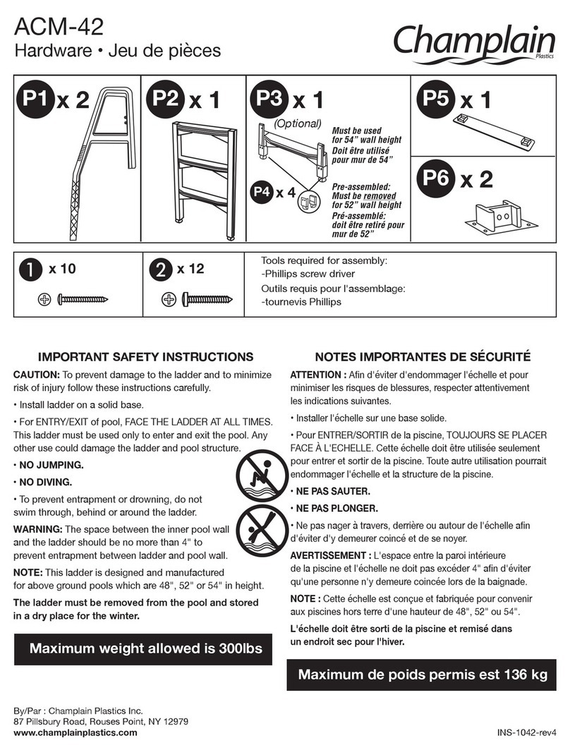
Champlain ACM-42 User manual

Champlain

Champlain ACM-42 User manual

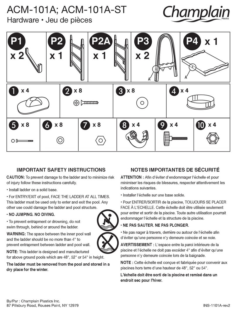
Champlain ACM-101A User manual

Champlain

Champlain ACM-101A User manual

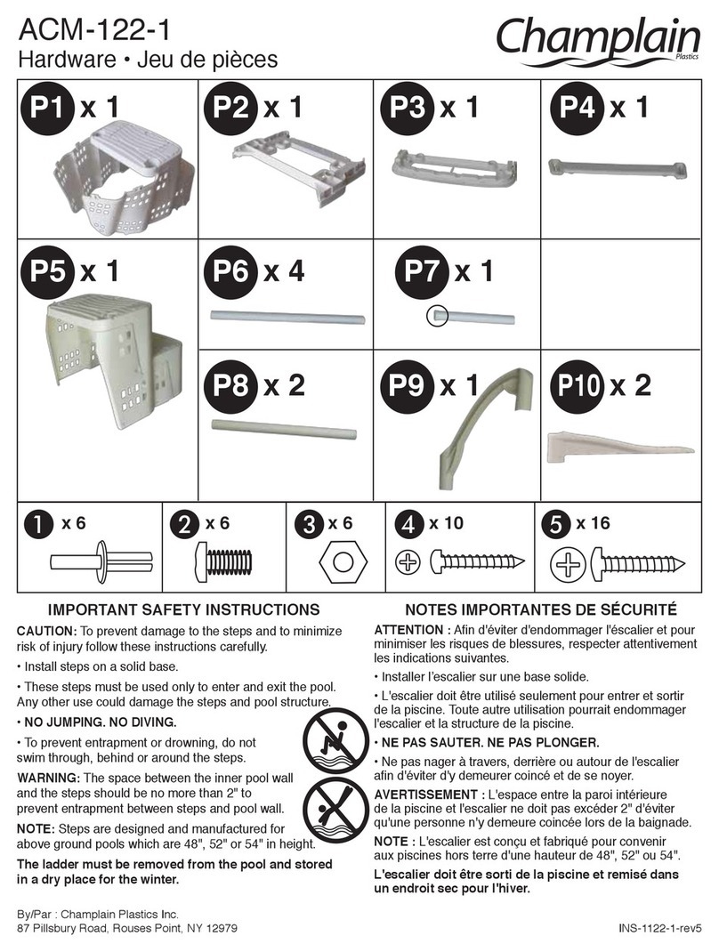
Champlain ACM-122-1 User manual

Champlain

Champlain ACM-122-1 User manual

Champlain ACM-124S User manual

Champlain

Champlain ACM-124S User manual

Champlain ACM-121S User manual

Champlain

Champlain ACM-121S User manual

Champlain ACM-197 User manual

Champlain

Champlain ACM-197 User manual

Champlain ACM-192 User manual

Champlain

Champlain ACM-192 User manual

Champlain ACM-122 User manual

Champlain

Champlain ACM-122 User manual

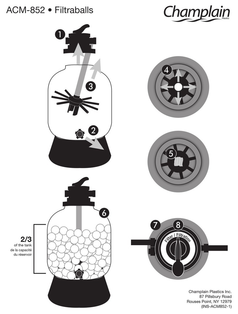
Champlain ACM-852 User manual

Champlain

Champlain ACM-852 User manual

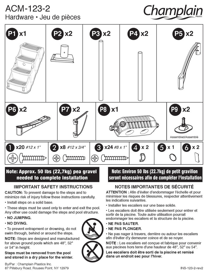
Champlain ACM-123-2 User manual

Champlain

Champlain ACM-123-2 User manual

Champlain ACM-41A User manual

Champlain

Champlain ACM-41A User manual

Champlain ACM-19296 User manual

Champlain

Champlain ACM-19296 User manual

Champlain ACM-19500 User manual

Champlain

Champlain ACM-19500 User manual

Champlain ACM-41AS User manual

Champlain

Champlain ACM-41AS User manual

Popular Lighting Equipment manuals by other brands

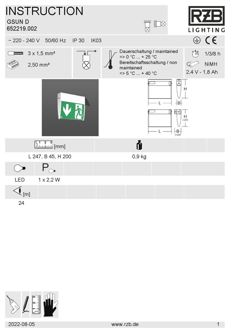
RZB Lighting GSUN D instruction manual

RZB Lighting

RZB Lighting GSUN D instruction manual

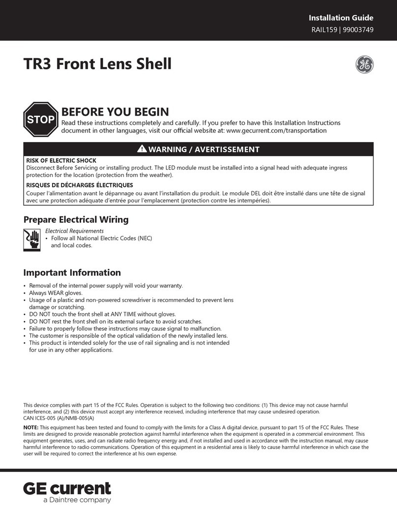
Daintree GE Current RAIL159 installation guide

Daintree

Daintree GE Current RAIL159 installation guide

Cooper Wiring Devices 7737 quick start guide

Cooper Wiring Devices

Cooper Wiring Devices 7737 quick start guide

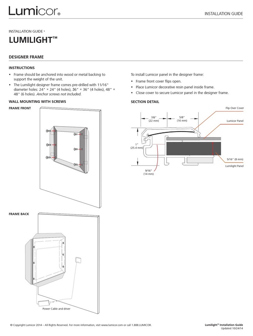
Lumicor LUMILIGHT installation guide

Lumicor

Lumicor LUMILIGHT installation guide

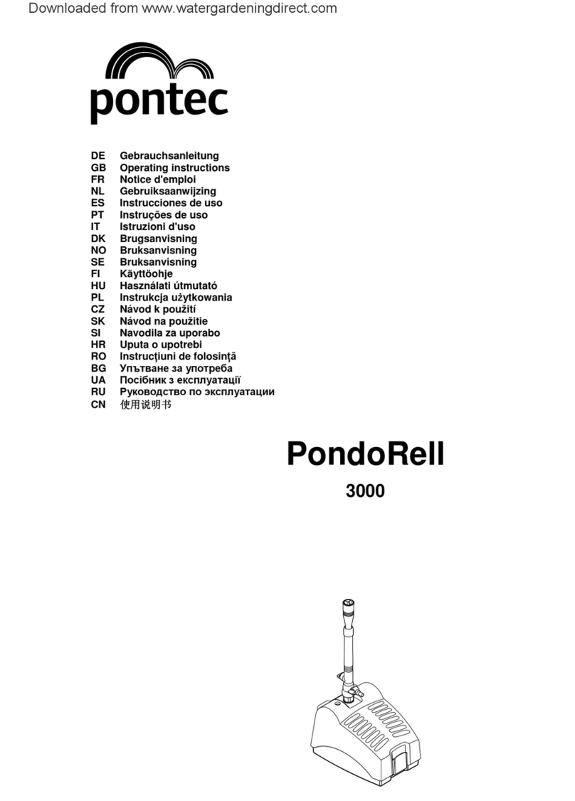
Pontec PondoRell 3000 operating instructions

Pontec

Pontec PondoRell 3000 operating instructions

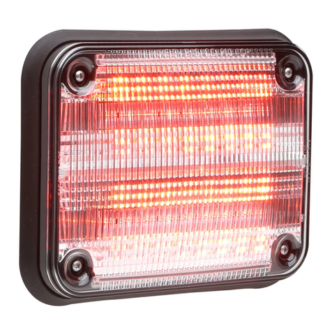
Whelen Engineering Company Super-LED 900 Series installation guide

Whelen Engineering Company

Whelen Engineering Company Super-LED 900 Series installation guide

ArchWork ARCGROUND3TRI user manual

ArchWork

ArchWork ARCGROUND3TRI user manual

Lampenwelt 9617017 quick start guide

Lampenwelt

Lampenwelt 9617017 quick start guide

Lithonia Lighting ECBG LED M6 manual

Lithonia Lighting

Lithonia Lighting ECBG LED M6 manual

DS Produkte U-LMS1 instructions

DS Produkte

DS Produkte U-LMS1 instructions

Maxspect Recurve R6-060 owner's manual

Maxspect

Maxspect Recurve R6-060 owner's manual

Vivosun AeroLight user manual

Vivosun

Vivosun AeroLight user manual

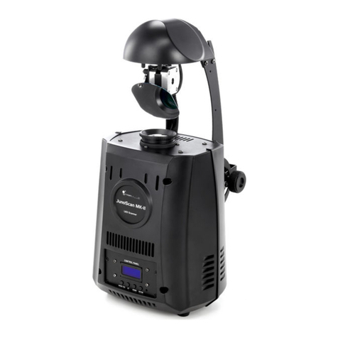
thomann JunoScan MK-II user manual

thomann

thomann JunoScan MK-II user manual

Clevertronics TS Trade Series Installation & maintenance instructions

Clevertronics

Clevertronics TS Trade Series Installation & maintenance instructions

ProLights STARDRAPE W user manual

ProLights

ProLights STARDRAPE W user manual

American DJ LED OPERATOR User instructions

American DJ

American DJ LED OPERATOR User instructions

EuroLite SLS-603 user manual

EuroLite

EuroLite SLS-603 user manual

BROOKING INDUSTRIES HORIZON manual

BROOKING INDUSTRIES

BROOKING INDUSTRIES HORIZON manual

manuals.online logo
manuals.online logoBrands
  • About & Mission
  • Contact us
  • Privacy Policy
  • Terms and Conditions

Copyright 2025 Manuals.Online. All Rights Reserved.