Visionary Solutions E4100 User manual

WWW.VISIONARYAV.COM
|
2060 Alameda Padre Serra, Suite 100 • Santa Barbara, CA 93103 • 805-845-8900
|
Visionary Solutions, Inc.
E4100 • Encoder |D4100 • Decoder User Manual

CONTENTS
Contents
INTRODUCTION .......................................................................................................................................... 1
NETWORK AV INFRASTRUCTURE PREREQUISITES ............................................................................................... 1
NETWORK REQUIREMENTS ............................................................................................................................................2
POWER OVER ETHERNET (POE) ......................................................................................................................................2
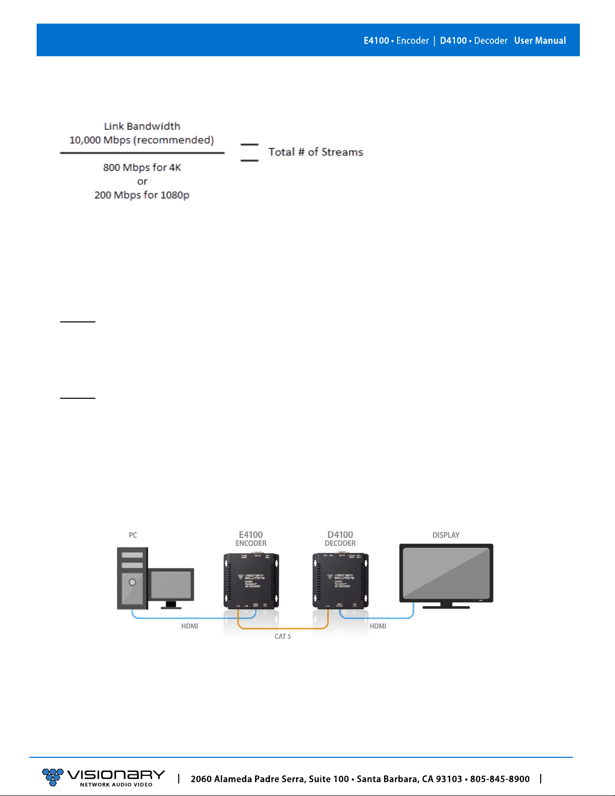
SWITCH SPEED............................................................................................................................................................2
CHOOSING AN ETHERNET SWITCH ...................................................................................................................................3
SWITCH GUIDELINES ....................................................................................................................................................3
IMPLEMENTATION CONSIDERATIONS ................................................................................................................................4
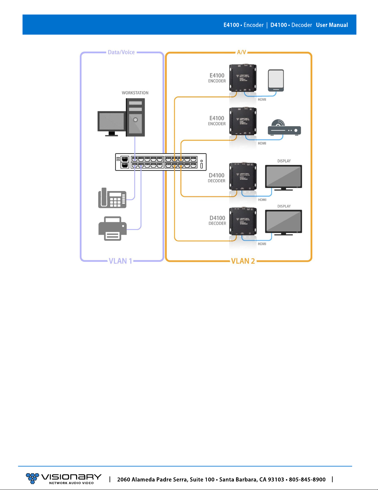
INSTALLING ON ACONVERGED NETWORK .........................................................................................................................4
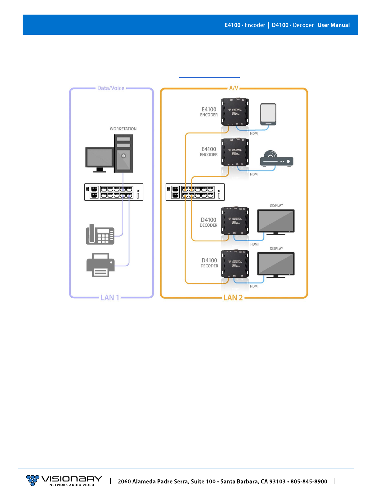
INSTALLING ON ADEDICATED NETWORK...........................................................................................................................6
SINGLE SWITCH NETWORKING ........................................................................................................................................6
MULTIPLE SWITCH NETWORKING ....................................................................................................................................6
INSTALLATION AND CONNECTIONS (SYSTEM EXAMPLES) ..................................................................................... 7
ONE SOURCE TO ONE DISPLAY .......................................................................................................................................7
ONE SOURCE TO MANY DISPLAYS ...................................................................................................................................8
MANY SOURCES TO MANY DISPLAYS ...............................................................................................................................9
MANY SOURCES TO MANY DISPLAYS WITH USB OVER IP (KVM) ........................................................................................10
VIDEO WALL ............................................................................................................................................................11
NETWORK DISCOVERY ................................................................................................................................................12
CONFIGURATION ...................................................................................................................................... 14
CONFIGURING ENCODER AND DECODER IP ADDRESSES .......................................................................................................14
CONFIGURING STREAM SETTINGS (MANUALLY) ................................................................................................................15
UNICAST MODE ........................................................................................................................................................15
MULTICAST MODE ....................................................................................................................................................15
STREAM BIT RATE......................................................................................................................................................15
STREAM FRAME RATE.................................................................................................................................................15
FAST(ER)SWITCHING .................................................................................................................................................16
USB OVER IP (KVM) ................................................................................................................................................16
AUTO SELECT MODE ..................................................................................................................................................16
ACTIVE PER REQUEST MODE (DEFAULT) .........................................................................................................................16
ACTIVE ON LINK MODE ..............................................................................................................................................16
FAST(ER)KVM SWITCHING .........................................................................................................................................16
RS-232 OVER IP ......................................................................................................................................................16
SIMPLE GUEST MODE.................................................................................................................................................16
CEC OVER IP (DECODER ONLY)....................................................................................................................................17
CEC API EXAMPLES ...................................................................................................................................................17
VIDEO FORMAT SETTINGS (DECODER ONLY) ....................................................................................................................18
AUDIO SETTINGS .......................................................................................................................................................18
AUDIO SOURCE.........................................................................................................................................................18
RTP AUDIO STREAM (ENCODER ONLY)...........................................................................................................................19
VIDEO WALL ............................................................................................................................................................20
EDID .....................................................................................................................................................................21
CUSTOM SPLASH SCREEN (DECODER ONLY) .....................................................................................................................22
ADVANCED CONFIGURATION....................................................................................................................... 22
VIDEO SOURCE TIMEOUT (DECODER ONLY) .....................................................................................................................22
VIDEO POWER SAVE (DECODER ONLY) ...........................................................................................................................22
HDCP FORCE ON......................................................................................................................................................22
HDCP FORCE OFF (ENOCDER ONLY)..............................................................................................................................22
GENLOCK (DECODER ONLY) .........................................................................................................................................22
VIDEO OUTPUT SETTING (DECODER ONLY) ......................................................................................................................23
OSD TEXT DISPLAY (DECODER ONLY) ............................................................................................................................23

MASS CONFIGURATION (DECODER ONLY) .......................................................................................................................23
ENCODER OPTIONS ................................................................................................................................... 24
E4100 ENCODER DEVICE TAB ......................................................................................................................................24
E4100 ENCODER NETWORK TAB ..................................................................................................................................25
E4100 ENCODER CONFIGURATION TAB ..........................................................................................................................26
E4100 SYSTEM TAB..................................................................................................................................................28
DECODER OPTIONS ................................................................................................................................... 29
D4100 DECODER DEVICE TAB......................................................................................................................................29
D4100DECODER NETWORK TAB..................................................................................................................................30
D4100 DECODER CONFIGURATION TAB.........................................................................................................................31
D4100 DECODER SYSTEM TAB.....................................................................................................................................35
CONTROL................................................................................................................................................ 36
VISION LITE..............................................................................................................................................................36
THIRD-PARTY CONRTOL DRIVERS AND PLUGINS .................................................................................................................42
API........................................................................................................................................................................42
TROUBLESHOOTING .................................................................................................................................. 42
LED INDICATORS .......................................................................................................................................................42
CHECKING THE FIRMWARE...........................................................................................................................................42
SUPPORT.................................................................................................................................................................42
FACTORY DEFAULT SETTINGS........................................................................................................................................42
DIAGNOSTICS PAGE ...................................................................................................................................................43
NETWORK INFO ........................................................................................................................................................43
VIDEO INFO .............................................................................................................................................................44
AUDIO INFO .............................................................................................................................................................45
USB INFO ...............................................................................................................................................................46
FLASH LEDS.............................................................................................................................................................47
TEMPERATURE..........................................................................................................................................................48
RACK MOUNT KIT .................................................................................................................................... 49
PRODUCT SPECIFICATIONS.......................................................................................................................... 50
©2022 Visionary Solutions, Inc. All rights reserved. PackeTV® and PacketAV® are trademarks of Visionary Solutions, Inc. in the United States and other countries. All
other brand names, product names
and
trademarks
are the property of their respective owners. Certain trademarks, registered trademarks, and trade names may be
used to refer to either the entities claiming the marks and names or their products. Visionary Solutions, Inc. disclaimsany interest in the marks and names of others.
Document Version: 221020

1
Introduction
INTRODUCTION
Visionary Solutions 4K UHD over IP cinema quality, ultra-low latency [~1 frame - visually lossless] encoder and decoder bypass the
constraints of traditional switch matrix distribution systems by harnessing the flexibility and scalability of converged IP networks.
With the growing demand for 4K UHD video, professional AV designers and IT directors–in an increasingly converged AV/IT
environment–can use Visionary Solutions products as an alternative to conventional distribution systems.
PacketAV E4200/D4200 is nothing short of a paradigm shift for networked AV. True convergence is finally here; a single platform to
support audio and Video over IP. Integrate 4K UHD video over IP into your audio network and bypass the constraints of traditional
switch matrix systems by harnessing the flexibility and scalability of converged IP networks.
Visionary’s PackeTV® and PacketAV® products can be deployed on any industry standard IP network. They can be used on existing
enterprise IP networks or on a physically separate parallel network [private network] to offload traffic, using the same network
protocols, methods, and devices but without intermingling video traffic with data or voice, and with equal ease of installation.
An encoder is connected to an [HDMI] AV source signal [a camera, STB, media player, PC or server, BluRay player, or digital signage
player, etc.]. The signal is converted into a packetized network stream that is compatible with off-the-shelf IGMP enabled Gigabit
Ethernet (GbE) switches (Jumbo Frames enabled). Using an existing CAT 5/6 infrastructure, users can connect CAT 5/6 to any decoder
anywhere on the same GbE network. The decoder takes the IP packets received over CAT 5/6 cables, converts them back into an
HDMI signal connecting directly to a display, delivering visually lossless video along with USB over IP (KVM) and RS-232 over IP
controls. A signal from any encoder can be sent to any decoder on the same network. The signals can easily be controlled with our
Vision Lite software to create different outputs on the display side, including video wall or matrix switching.
NETWORK AV INFRASTRUCTURE PREREQUISITES
This section is intended to provide a basic understanding of applicable networking technologies and the infrastructure requirements
needed for a successful Visionary Solutions E4200/D4200 system installation, and to ensure a rapid deployment and seamless
integration. Many network issues can be minimized or solved before they occur with appropriate knowledge and proper planning.
The E4200/D4200 will work with most non-blocking, IGMP with IGMP Snooping, 8K or better Jumbo Packet 1GbE network
switches. At least one layer-3 switch with IGMP-query capability is required. For PIM (multicast routing) of E4200/D4200 video
streams, the network switches would need to be capable of PIM (Sparse, Dense, or Sparse-Dense).
Do not connect any encoders or decoders to aswitch until the switch is configured for multicasting and IGMP Snoopingis enabled.
Check with your switch manufacturer for the default configuration settings.
NETWORK PROTOCOLS
All data on a network is encapsulated in packets, according to the TCP/IP protocols. Data packets are routed through the network to
their destination(s) by switches using information in the header of IP packets. Transmission can be unicast or multicast. Unicast
transmissions are point-to-point, from a single source to a single destination. Multicast transmissions originate from a single device
and are received by a group of devices on the network, according to the Internet Group Management Protocol (IGMP). Multicast
transmission is ideal for bandwidth-intensive application such as media distribution as it allows for efficient use of network
bandwidth. Only a single copy of the data is distributed to multiple destinations. On the other hand, unicast distribution of media to
multiple destinations is an extremely inefficient use of network bandwidth because duplicate copies of the data are sent, point-to-
point, from the source to each destination. E4200/D4200 devices make use of the multicast protocol.
More information concerning IGMP may be found here at:
http://docwiki.cisco.com/wiki/Internet_Protocol_Multicast#Internet_Group_Management_Protocol

2
Network AV Infrastructure Prerequisites
There are two ways to implement multicast routing when using our equipment:
• IGMP (Internet Group Management Protocol): Allows video streams (groups) to be dynamically routed only to those ports
requesting the video stream. The IGMP feature prevents the multicast video traffic from flooding the network and can
significantly reduce traffic in a layer-3 network. This is the recommended setting for our equipment.
• PIM (Protocol Independent Multicast): Functions independently of IP routing protocol. PIM Dense Mode (PIM-DM) is less
preferred for this application because it floods the network using unicast routing protocols to build routing tables. For more
information, visit: http://docwiki.cisco.com/wiki/Internet_Protocol_Multicast#Protocol-Independent_Multicast.
NETWORK REQUIREMENTS
For help determining the network requirements for your Visionary Solutions installation, please contact support@visionary-
av.com.
POWER OVER ETHERNET (POE)
Power over Ethernet (PoE) is a system that uses an PoE Ethernet switch as a power source to provide both electrical power and data
over a single cable to devices on a network, such as the E4200/D4200 devices. This reduces the number of cables and power supplies
that are required to power the devices in the network. The result is lower cost, less downtime, easier maintenance, and greater
flexibility for the network installation.
When selecting a PoE power supply scheme, is it important to select a PoE Ethernet switch that is capable of providing enough
power per port, as well as total power to accommodate all devices simultaneously. You should plan on the maximum available PoE
power per port for E4200/D4200 (15.4W). In some operating conditions less power will be demanded per E4200/D4200, call
Visionary Solutions for details.
To calculate the number of devices that can be used on a PoE Ethernet switch, divide the total PoE power capability of the switch by
the power required for each port and round down. For example, many PoE Ethernet switches can provide up to 370W of DC power. If
each port needs 15.4W of power, a switch can supply power to a total of 24 ports.
Examples:
• A Cisco SG300-52P has a PoE power output of 375W and the ports require 15.4W: 375 / 15.4 = 24.35. Therefore, 24 devices can
be powered by this switch.
• A Cisco SG300-52MP has a PoE power output of 740W and the ports require 15.4W: 740 / 15.4 = 48. Therefore, 48 devices can
be powered by this switch.
Some switches can only supply PoE power to a certain number of ports. If it is necessary to use this type of switch, PoE injectors can
be used or a local power supply can be provided for the switch, or you may need to disable the detection of the PoE for those ports in
the Ethernet switch.
Exceeding the PoE switch limit can cause erratic behavior on the network system. The PoE switch cuts power to prevent overloading,
which may cause units to reset at seemingly random intervals.
PoE specification standards are:
• IEEE 802.3-2008 provides up to 10W of DC power.
• IEEE 802.3af provides up to 15.4W of DC power. Only 12.95W is assured to be available at the device.
• IEEE 802.3at, known as PoE+ or PoE plus, provides up to 32W of DC. Only 25.5W is assured to be available at the device.
Class 0 devices comply with the PoE standard that provides up to 15.4W of DC power for each port. The real power draw is between
5-10W.
Class 3 devices comply with IEEE 802.3-2008 that provides up to 10W of DC power.
SWITCH SPEED
The E4200 encoder will produce up to 800Mb/s of data. Therefore, 10 encoders will require 10 x 800MB/s = 8Gbps. E4200/D4200
requires the switch to be GbE. E4200/D4200 technology is used to transmit visually lossless 8~10:1 compressed video up to 4K along
with other AV signals such as audio, USB, and control signals. For video alone, this means raw bandwidth of up to 800Mbps for 4K.

3
Network AV Infrastructure Prerequisites
CHOOSING AN ETHERNET SWITCH
Switches must support these functions:
• Jumbo Frames (enabled)
• IGMP Snooping
• IGMP Querier
• IGMP Snooping Fast Leave
If the switches are used for multi-switch networking, they must also support PIM Routing (Sparse, Dense, or Sparse-Dense).
These features may be helpful as well:
• Dynamic multicast router port
• Forwarding unknown multicast to multicast router ports only
Any network switch should have a backplane capacity of at least (2 x 1000-Mbps x N) where N is the number of ports on the switch
passing the video traffic. For example, a 24-port switch where all available ports may be used to pass video traffic should have a (2 x
1000 x 24) = 48Gbps backplane. One channel of encoder video can be sent or received from each port in this switch example
although full bandwidth may not be used at any one time.
The maximum distance between devices is 100m (328ft) over CAT 5e (or better) cable. This distance can be extended in increments of
100m (328ft) by using a gigabit switch as a repeater between devices. Copper to fiber adapters can extend the maximum distance
between devices up to 10km through the use of fiber.
Since different brands and models of switches perform differently when handling multicast IP packets, functional verification and
pressure testing are also recommended in any installation. Switches that perform well in smaller installations may not work well in
larger installations. Recommended configuration settings may vary based on your switch.
Visionary Solutions offers sample switch configuration files, optimized for Network AV, for certain switch brands/models for testing
purposes. Contact support@visionary-av.comto obtain the files.
SWITCH GUIDELINES
1. Enable IGMP querying and snooping (set IGMP Version to IGMP V2 if the switch is capable). To enable the transmission of a
source to multiple destinations, E4200/D4200 devices make use of multicast. The default behavior of a layer-2 switch is to
broadcast those packets, which means that every packet will be transmitted to all possible destinations. IGMP snooping checks
IGMP packets passing through the network, picks out the group registration, and configures multicasting accordingly. A layer-2
switch supporting IGMP Snooping can passively snoop on IGMP Query, Report, and Leave (IGMP version 2) packets transferred
between IP multicast routers/switches and IP multicast hosts to determine the IP multicast group membership. This is why any
network switch used with E4200/D4200 must support IGMP Snooping. Our end points use IGMP protocol to assign the end
points into multicast groups and the router uses IGMP snooping to efficiently route multicast packets only to the receivers that
want to receive them.
IGMP Snooping is used to identify multicast IP packets, assign IP packets into multicast groups so that the router only sends to
devices that want to receive the packets, establish membership in a multicast group, and register a router to receive designated
multicast traffic. Multicast filtering is achieved by dynamic group control management. Many switches have the IGMP Snooping
feature disabled by default and manual configuration is required. Often, checking the Enable IGMP Snooping option is the only
setting needed to enable IGMP Snooping. Implementing IGMP Snooping is vendor specific and additional configuration is often
needed.
IGMP Snooping Querier is used to send out group
membership
queries on a timed interval, retrieve IGMP
membership
reports
from active
members,
and update the group
membership
tables. The Leave Group packet is sent when a device wants to leave a
group.

4
Network AV Infrastructure Prerequisites
Because multicasting video traffic can flood a network and
significantly
reduce the flow of traffic, it is important to ensure that
your
network infrastructure
and
backbone
switches support IGMP
Snooping
so that your core network is able to ignore the traffic
streams multicasting can generate. By default, all multicast traffic should be blocked until requested by a multicast
group member.
Without IGMP Querying/Snooping, multicast traffic is treated in the same manner as a broadcast transmission, which forwards
packets to all ports on the network. With IGMP Querying/Snooping, multicast traffic is only forwarded to ports
that are
members of that multicast group. IGMP Snooping generates no additional network traffic, which significantly reduces the
multicast traffic passing through your switch.
Note: Some
switches
require that the routing table be
pre-loaded
so that the
switch
does not have to
interrogate
each IP packet to
determine its
destination.
Static routing can be used to route multicast traffic.
Protocols
similar to Generic Routing Encapsulation
(GRE) can be used to
encapsulate
multicast packets in unicast wrappers for
point-to-point transmission
between switches, and
when the packets arrive at the destination IP address, the unicast wrapper is removed.
2. Enable Fast Leave. The switch may also support IGMP
Snooping
Fast Leave, which shortens the time takes for a device to leave a
group and be made available to join to a different group. A switch can be informed that a device wants to leave a multicast
channel by sending it a IGMP Leave Group packet. Once received, the time it takes for the switch to apply the new configuration
may vary from one switch to another. Most switches have a Fastleave configuration option. When enabled, Fastleave speeds up
the time needed for a port assigned to one multicast group to leave the group and join a different multicast group. This
significantly reduces the video switching time. Always enable the Fastleave option when it is available.
3. Allow multicast traffic on all network ports through which video streams pass.
4. Ensure current Access Control Lists (ACLs) are not filtering multicast or control traffic.
5. Remove Flow Control and/or Storm Control on any network port passing the video stream.
6. Enable VLANs to separate video traffic from data and voice.
7. Enable Jumbo Frames.
8. Disable Green Ethernet (or efficiency mode). Some switches have the ability to lower the power consumption on the ports as a
“Green” feature. This can cause issues with bandwidth intensive devices (like our encoders and decoders).
IMPLEMENTATION CONSIDERATIONS
E/D4100 devices can be installed on a physically separate network or converged onto an existing GbE network. When implementing,
it is important to decide at the earliest stages of planning if the system will be integrated into the rest of the network or if it will
reside on a dedicated AV network. Each has its own advantages and disadvantages, but wherever possible we recommend the use
of
a
dedicated AV switch. Using the existing network is of course possible–but it adds extra complexity to the installation and often
removes control of the networking equipment from the site’s AV staff or installer.
The first thing to consider is how much control the install and site teams have over the network configuration. Do they have access
and clearance to change the managed switch configurations on the fly? Is the network administrator willing to make the necessary
changes to support multicast and IGMP traffic on their network? Will they allow the creation of a VLAN or change their existing
VLAN configuration to support the required configuration? If the answer to these questions is no, then it is highly recommended that
the system be installed on a separate dedicated network switch. If this is not an option, then a conversation needs to take place with
the network admin staff to ensure they are aware of the requirements.
INSTALLING ON ACONVERGED NETWORK
Figure 1 illustrates how E/D4100 endpoints can be installed on an existing (converged) network. When using an existing
infrastructure, a dedicated VLAN is recommended to separate the AV traffic from other network data. All switches that will handle
AV traffic must be 1 GbE capable per the specifications in Network Requirements.
Visionary Solutions recommends that all encoders be turned off before connecting to an existing network. Once connected,
encoders can be turned on one at a time to determine network impact.

5
Network AV Infrastructure Prerequisites
Figure 1. Converged Network Diagram

6
Network AV Infrastructure Prerequisites
INSTALLING ON ADEDICATED NETWORK
Figure 2 illustrates how E/D4100 endpoints can be installed on a dedicated network. A dedicated network is recommended for
transmitting AV over IP. We offer various models of preconfigured switches for resale to our partners. These switches are shipped
pre-configured for AV over IP from the factory. Please contact sales@visionary-av.com for more information.
Figure 2. Dedicated Network Diagram
SINGLE SWITCH NETWORKING
Single switch networking can be used when there are no more than 100m (328ft) from the central distribution point. Any network
switch should have a backplane capacity of at least (2 x 1000-Mbps x N) where N is the number of ports on the switch passing the
video traffic. For example, a 24-port switch where all available ports may be used to pass video traffic should have a (2 x 1000 x 24) =
48Gbps backplane.
MULTIPLE SWITCH NETWORKING
The maximum distance between devices is 100m (328ft) over CAT 5e (or better) cable. This distance can be extended in increments
of 100m (328ft) by using a gigabit switch as a repeater between devices. Copper to fiber adapters can extend the maximum distance
between devices up to 10km through the use of fiber.
When using multiple switches, we recommend at least 10Gbps bi-directional connections between switches.
• (Link Bandwidth)/(800Mbps) = Number of simultaneous streams across link for 4K and (Link
Bandwidth)/(200Mbps)
= Number
of simultaneous streams across link for 1080p.
• The maximum number of streams possible between switches = link bandwidth (10Gbps) / 800Mbps (for 4K) x number of
encoders (or 200Mbps for 1080p).

7
Installation and Connections (System Examples)
• For 4K streaming, the total number of streams (800xn) must be ≤ 10,000.
• For 1080p streaming, the total number of streams (200xn) must be ≤10,000.
INSTALLATION AND CONNECTIONS (SYSTEM EXAMPLES)
This section provides installation and connection instructions for five configuration examples. For each encoder and decoder in the
system examples below, follow these step-by-step connection instructions.
1. Use an HDMI cable to connect the AV source to the HDMI Input port on the encoder unit.
2. (Optional) Use a second HDMI cable to connect the HDMI Loop-through port on the encoder unit to a local display.
3. Connect an HDMI cable from the display to the HDMI Output port on the decoder unit.
4. Connect a CAT 5 (or better) cable from the Ethernet port on the encoder unit to a PoE port on the network switch.
5. Connect a CAT 5 (or better) cable from the Ethernet port on the decoder unit to a PoE port on the network switch.
6. (Optional) Connect the included 5V DC power supplies to both the encoder and decoder units. Connect the included AC power
cords from the power supplies to available electrical outlets.
ONE SOURCE TO ONE DISPLAY
In this basic installation scenario, sending video from a single source to a single display, a single encoder and decoder (point-to-
point) can be linked directly together or over a network. If linked directly, the CAT 5e (or better) cable linking the devices should not
run more than 100m (328ft).
The devices do not connect automatically and must first be configured through embedded web interfaces. This step requires a
connection to a network. Once the devices are linked on the network, they can be connected directly. See section Configuration.
Figure 3. One Source to One Display Diagram

8
Installation and Connections (System Examples)
ONE SOURCE TO MANY DISPLAYS
Sending video from a single source to multiple displays requires a network switch. A single encoder can be linked to multiple
decoders (point-to-multipoint) over a network. Implementing a one to many installations dramatically decreases the amount of
equipment required at the source location.
The encoder and each decoder can be located no more than 100m (328ft) from the switch.
Figure 4. One Source to Many Displays Diagram

9
Installation and Connections (System Examples)
MANY SOURCES TO MANY DISPLAYS
Sending video from multiple sources to multiple displays requires a network switch. Multiple encoders can be linked to multiple
decoders
(multipoint-to-multipoint)
over a network. The many encoders to many displays’ configuration allows almost any number
of sources and displays. Multiple switches can be linked by fiber, providing flexibility and scalability, and expanding the size and
reach of the configuration to a practically limitless scale.
Each encoder and each decoder can be located no more than 100m (328ft) from the switch.
Figure 5. Many Sources to Many Displays Diagram

10
Installation and Connections (System Examples)
MANY SOURCES TO MANY DISPLAYS WITH USB OVER IP (KVM)
Allowing users to remotely access and control computers from multiple sources with multiple displays requires a network switch.
Multiple encoders can be linked to multiple decoders
(multipoint-to-multipoint)
over a network. The many encoders to many
displays’ configuration allow almost any number of sources and displays. Multiple switches can be linked by fiber, providing
flexibility and scalability, and expanding the size and reach of the configuration to a practically limitless scale.
Each encoder and each decoder can be located no more than 100m (328ft) from the switch.
Figure 6. Many Sources to Many Displays with USB over IP Diagram

11
Network Discovery
VIDEO WALL
The video wall configuration requires a network switch to display multiple video sources to many displays or a single display in any
combination of video streams. Multiple encoders can be linked to multiple decoders
(multipoint-to-multipoint)
over the network.
The video wall configuration allows almost any number of sources and displays. Multiple switches can be linked by fiber, providing
flexibility and scalability, and expanding the size and reach of the configuration to a practically limitless scale.
Each encoder and each decoder can be located no more than 100m (328ft) from the switch.
Figure 7. Video Wall Diagram

12
Network Discovery
NETWORK DISCOVERY
Discover your E/D4100 endpoints on the network.
By default, the encoders and decoders are shipped from the factory in DHCP mode with Auto IP Failover. In DHCP mode, each
encoder and decoder unit is automatically assigned a unique IP address by the DHCP server. If there is no DHCP server on the
network, the encoders and decoders (after about one minute) will “failover” to Auto IP mode where each encoder and decoder unit
assigns itself a unique IP address within the range of
169.254.1.0–169.254.254.255,
with a 255.255.0.0 subnet mask and a gateway
address of 169.254.0.254.
To configure the units, you must access the web interface of each encoder and decoder using a computer.
In order to communicate with the E/D4100 endpoints, the devices must be on the same subnet as your computer. You may need to
change the computer’s network settings to accomplish this.
On a Microsoft Windows computer, configure your network settings as follows:
1. Click Start menu, go to Control Panel > Network and Sharing center > Change Adapter Settings > Local Area Connection. Right-
click andchoose Properties.
2. Highlight Internet Protocol Version 4 (TCP/IPv4) then click Properties. This opens the window you use to configure your
network settings.
To set up your computer to communicate with endpoints that are using DHCP:
• Method 1: If there is a DHCP server on the network, accept Obtain an IP address automatically (the default). The computer will
be automatically assigned a unique IP address by the DHCP server on the same subnet, allowing communication with the E/
D4100 endpoints.
• Method 2: Configure your computer with a static IP address within the defined DHCP range for your network (the subnet (VLAN)
defined by the DHCP netmask for your network). Choose Use the following IP address. Enter an IP address then click OK. To
avoid address conflicts, enter a static address that is not in the range of addresses that will be given out by the DHCP server. For
example: If the DHCP range = 192.168.1.100 –192.168.1.150 and netmask = 255.255.255.0, you can assign 192.168.1.151.
To set up your computer to communicate with endpoints that are using Auto IP:
• Method 1: If there is no DHCP server on the network, a Windows PC will “failover” to Auto IP in a similar way as the encoders
and decoders. Accept Obtain an IP address automatically (the default). After about one minute the computer will assign itself a
unique IP address within the range of
169.254.1.0–169.254.254.255,
with a 255.255.0.0 subnet mask, allowing communication

13
Network Discovery
with the encoders and decoders on the network that are also assigned IP addresses via Auto IP.
• Method 2: If the computer already has a statically-assigned IP address:
1. Click Advanced > Add.
2. Click Add to enter a unique IP address within the range of
169.254.1.0–169.254.254.255,
with a subnet of 255.255.0.0.
• Method 3: Configure the computer with a unique static IP address within the range of 169.254.1.0 –169.254.254.255, with a
subnet of 255.255.0.0. If your address is not unique conflicts will occur.
There are multiple ways to discover (find the assigned IP address) the encoders and decoders on your network.
1. Use the Vision Lite application to auto-discover units. RECOMMENDED – refer to section Vision Lite.
2. Look at the DHCP server list of assigned IP addresses.
3. Use avahi‐browse (requires avahi-daemon to be running) to find the unit IP addresses.
4. Using a Linux operating system (OS) on the network, ping 226.0.0.19 from the same subnet (VLAN) as the unit to return a list of
assigned IP addresses. On a Windows OS, the ping command only displays the first responding address.
5. Use nmap to scan for Visionary Solutions MAC Addresses.
6. For decoders only: Connect to the network via HDMI to a display. The IP address displays on the bottom right of the Boot up
screen image on the display device when there is no source connected.

14
Encoder Options
Once discovered, you can use the embedded web interface on each encoder and decoder unit to configure and change the network
settings. To log in to the web interface, enter the unit’s IP address in a web browser for the URL OR click the IP address in the Vision
Lite application Configuration page. Log in with
username
=
admin
password=admin.
CONFIGURATION
CONFIGURING ENCODER AND DECODER IP ADDRESSES
As previously mentioned, by default, the encoders and decoders are shipped from the factory in DHCP mode with Auto IP Failover.
For a permanent installation, and to ensure system consistency, it is recommended to configure all of the encoders and decoders
with static IP addresses.
Important: IP configuration changes must be done correctly to avoid any communication disruptions with the units. Communication
with the Vision Lite Server and the computer that the application resides on is dependent upon the computer being in the same IP
address range as the encoders and decoders on the network. Therefore, before making any IP address changes to the units, we
recommend having two statically-assigned IP addresses on the computer.
When using DHCP, configure the first static IP address to an address within the defined DHCP range for your network (the subnet
(VLAN) defined by the DHCP netmask for your network). Be sure that the static address you assign is not in the range of addresses
that will be given out by the DHCP server to avoid address conflicts. For example: If the DHCP range = 192.168.1.100 – 192.168.1.150
and netmask = 255.255.255.0, you can assign 192.168.1.151.
When using Auto IP, assign an address within the range of 169.254.1.0 – 169.254.254.255, with a 255.255.0.0 subnet mask
AND
Configure a second static IP address in the range of the IP addresses you are planning to assign to the units.
Assign new IP addresses to the encoder and decoder units as follows:
1. Access the web interface for the encoder or decoder unit.
2. Log in with
username
=
admin
password=admin.
3. Click the Network tab.
4. Set IP.MODE to Static.
5. Set the IP.ADDRESS. Example: 192.168.1.45
6. Set the IP.NETMASK. Example: 255.255.255.0
7. Set the IP.GATEWAY. Example: 192.168.1.1
8. Set the IP.DNS_SERVER (optional). Example: 4.2.2.1
9. Click Save to save the new settings. The unit will automatically reboot.
The unit is now configured with the new network settings.
Once the initial configuration is complete, you will be primarily using the Vision Lite matrix routing control software (or other third
party control systems) to route the encoder and decoder streams to each other. When using these systems, the STREAM.HOST
setting, described in the following sections, are automatically updated each time a routing/switch occurs.
In the absence of a control system, it is still possible to manually configure the stream settings. The instructions are included
below.

15
Encoder Options
CONFIGURING STREAM SETTINGS (MANUALLY)
UNICAST MODE
The term unicast is used to describe a configuration where information is sent from one point to another point. A unicast
transmission sends IP packets to a single recipient on a network. It is possible to have multiple encoder and decoder units connected
in a system. However, in unicast mode, an encoder unit can communicate with only one decoder unit at a time (see Figure 1).
1. Access the web interface for the encoder and decoder units that will be using unicast mode.
2. Log in with
username
=
admin
password=admin.
3. Click the Configuration tab.
4. Set STREAM.MODE to Unicast.
5. On the decoder:
a. Set STREAM.HOST to the IP address of the encoder that the decoder is tuned in to.
b. Click Save on to save the new settings. The unit will automatically reboot. The units are now connected in unicast mode.
MULTICAST MODE
The term multicast is used to describe a configuration where information is sent from one or more points to a set of other points. For
example, a single encoder unit can transmit data to multiple decoder units. In addition, if multiple encoder units are used, each
encoder unit can transmit data to any decoder that is not already receiving data from another encoder unit (see Figures 2-5).
Note: Visionary’s E/D4100 encoders default to a multicast stream address based on their host IP address. The multicast stream
address is handled in the background and does not need to be configured. If the multicast stream address needs to be known, it will be
225.2.x.x, x.x = last two octets of the encoder host IP address. Example: an encoder with a host IP address of 192.168.8.101, would have a
multicast stream address of 225.2.8.101.
1. Access the web interface for the encoder or decoder unit that will be using multicast mode.
2. Log in with
username
=
admin
password=admin.
3. Click the Configuration tab.
4. Set STREAM.MODE to Multicast.
5. On the decoder:
a. Set STREAM.HOST to the IP address of the encoder that the decoder is tuned in to.
b. Click Save to save the new settings. The unit will automatically reboot.
6. Repeat steps 1–4 and step 6 for each decoder you want to tune into the encoder’s multicast stream.
The units are now connected in multicast mode.
STREAM BIT RATE
The bit rate (STREAM.BIT_RATE) defaults to auto. This means that the encoder will choose the optimal bit rate for the input
resolution and content. This can range up to a maximum of 850Mbps for highly complex 4K video. If you are trying to limit
bandwidth used, you can set this to 200Mbps (this gives excellent 1080P60) down to 50Mbps. You can experiment with your normal
content and see what bit rate setting is best for your use case, or just leave this in auto if you are not limited on bandwidth between
switches.
STREAM FRAME RATE
The frame rate
(
STREAM.FRAME_RATE
)
of the incoming video may be reduced to allow higher resolutions at lower bandwidth. For
instance, you might have 1080P60 content that is of slow moving scenes or other less complex video. You could then use the 50%
setting to lower the frame rate to 30fps. You could also set the stream bit rate to a lower value to make sure that the stream only
uses that amount of bandwidth.

16
Encoder Options
FAST(ER)SWITCHING
Below are some options for decreasing switch time (faster switching):
1. Set the decoders to scale the HDMI output for the monitor resolution. This is the VIDEO.FORMAT value on the config.html page.
If the decoders are set to
VIDEO.FORMAT=SOURCE
then switching time can be longer due to changes in format.
2. All of the sources must have the same resolution and refresh rate. Ensure that the encoders’ input format matches the formats
of the monitors connected to the decoders. Make sure that all encoders are using
VIDEO.HDCP_FORCE_ON,
or that all sources
are the same (HDCP on or off but not a mix).
USB OVER IP (KVM)
When connecting USB devices to encoders and decoders, the function is similar to that of a video matrix. Connecting a computer to
an encoder unit and a Human Interface Device (HID) device to a decoder unit allows you to control the computer from the decoder
unit.
USB over IP enables non-isochronous USB devices to be used remotely. USB over IP is enabled by default.
There are three USB modes available: Auto Select, Active per Request, and Active on Link.
AUTO SELECT MODE
The device chooses between Active per Request or Active on Link mode based on the casting mode (multicast or unicast) chosen.
• Multicast uses Active per Request.
• Unicast uses Active on Link.
ACTIVE PER REQUEST MODE (DEFAULT)
The USB connection initiates once a decoder and encoder are communicating. Multiple decoders can communicate with and have
simultaneous USB control of the same encoder. All decoders automatically activate USB control of the encoder they switch to, and
every decoder watching that encoder has USB control.
ACTIVE ON LINK MODE
Multiple USB devices may be connected to one or more decoder units. However, only one encoder unit can have USB control at a
time. In other words, only one decoder can communicate with the encoder at any given time. By default, the first decoder unit
connected has USB control.
FAST(ER)KVM SWITCHING
USB.KVM_FAST: Default FALSE. When set to TRUE (Checked) allows for rapid transition of KVM control when switching between two
encoders. Not compatible with touchscreen. Both the encoder and decoder need to have the value of setting match (and a reboot) to
take effect.
RS‐232 OVER IP
The encoders and decoders support RS-232 over IP and RS-232 pass-through, allowing the control of remote RS-232 devices. The
encoder and decoder units used to pass through the RS-232 data must be set to the same baud rate as the RS-232 host and client. In
unicast mode, an encoder unit is able to communicate with only one decoder unit at a time. In multicast mode, an encoder unit is
able to communicate with multiple decoder units simultaneously.
SIMPLE GUEST MODE
Bi-directional IP/Ethernet to RS-232 (Static Baudrate).
This mode requires an Ethernet (telnet) connection at the sending end and an RS-232 cable at the responding end. Commands are
entered via a TCP or telnet connection to port 6752. Anything entered into the TCP or telnet session at the sending side will be sent
out of the RS-232 port on the responding side.

17
Encoder Options
1. Access the web interface for the encoder or decoder unit and log in with
username
=admin
password=admin.
2. Click the Configuration tab.
3. Set SERIAL.MODE to Simple Guest.
4. Locate the SERIAL.SETTINGS and change the RS-232 settings to match the settings of the RS-232 device being used. See
example in the table below.
Table 2. RS‐232 Settings for an Example RS‐232 Device
Description
Setting
Baud Rate
19200
Data Bits
8
Parity
None
Stop Bits
1
5. Set SERIAL.ENABLED to true by clearing the False check box.
6. Click Save. The unit will automatically reboot.
7. Connect using telnet or other TCP socket port6752 to the IP address of the encoder or decoder connected to the responding RS-
232
device.
8. Send commands.
Pin 2: RXD
Pin 3: TXD
Pin 5: GND
Figure 8. RS‐232 Connector Pinout Diagram
CEC OVER IP (DECODER ONLY)
The decoders support CEC over IP, allowing control of a CEC (Consumer Electronics Control) enabled display through the HDMI
connection. The decoder receives the CEC commands and passes the commands through the HDMI connection to the CEC enabled
display. CEC commands may be triggered by the decoder web UI (System tab) or using API commands. The API uses references
commands to trigger the desired CEC action or control.
CEC-O-Matic (https://www.cec-o-matic.com) is a website that may be used to assist as a general reference when testing and
configuring CEC. Type the reference commands into CEC-O-Matic and it should decode reference and describe the specific purpose
or command for that code. The site can also assist when configuring the syntax of a new command.
Note: The TV/display has CEC enabled (Samsung calls it Anynet+). The setup menu of the display may be needed to enable this
feature.
CEC API EXAMPLES
On CEC Command: CMD=START&UNIT.ID=ALL&VIDEO.SEND_CEC_GENERIC=10:04&CMD=END
•Reference Command: 10:04
This manual suits for next models
1
Table of contents
Other Visionary Solutions Media Converter manuals