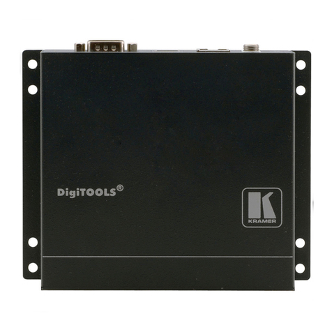
Vislink RCD9 User manual

Vislink, Waterside House, Earls Colne Business Park, Colchester, Essex, CO6 2NS, UK
Telephone: +44 (0)1442 431300 ●Facsimile: +44 (0) 1494 775356 ●Email: sales@vislink.com ●Website: www.vislink.com
Company Registered in England & Wales no. 10523708 ●VAT registration no. GB 260 012 169
Registered Office: Waterside House, Earls Colne Business Park, Colchester, Essex, CO6 2NS, UK
RCD9
2/4-Way Diversity
Receiver
User Manual

Issue No: 1 Page: ii
Ref: RCD9-ASUM-7001 Copyright © 2017 IMT Ltd, trading as Vislink
Document Disclaimer
The information contained in this manual remains the property of Vislink and may not be
used, disclosed or reproduced in any other form whatsoever without the prior written
permission of Vislink.
Vislink reserves the right to alter the equipment and specification appertaining to the
equipment described in this manual without notification.
This document is supplied on the express terms that it is to be treated as confidential and
that it may not be copied, used or disclosed to others for any purpose except as authorized
by Vislink.
Conventions
NOTE: Notes show to convey additional information.
CAUTION: Cautions show where potential equipment damage could occur.
WARNING: Warnings show where there is potential for personal danger or risk of death.
Read all warnings and understand them before carrying out work on any
equipment. This includes peripherals and any related equipment in use. The
danger is real and not reading and understanding the warning could lead to
injury, harm or potential death.
Service/Support Contacts:
Region
Contact Details
Worldwide
+44 (0) 1442 431410
Americas
+1 978 330 9292
When contacting Technical Support, please include the following information:
Model number and serial number of the unit (located on a label on the bottom of
each unit).
………………………………………….
Approximate date of purchase.
………………………………………….

Issue No: 1 Page: iii
Ref: RCD9-ASUM-7001 Copyright © 2017 IMT Ltd, trading as Vislink
Document History
Version
Date
Modification
Firmware Version
1
9//8/2017
First release of document.
-

Issue No: 1 Page: iv
Ref: RCD9-ASUM-7001 Copyright © 2017 IMT Ltd, trading as Vislink
Table of Contents
1. General Information .................................................................................................. 1
General Safety Information........................................................................................................1
Disposal Instructions..................................................................................................................2
Environmental............................................................................................................................2
Health & Safety ..........................................................................................................................3
Maximum RF Power Density Limits ...........................................................................................4
2. Introduction .............................................................................................................. 5
3. Specifications ............................................................................................................ 7
Dual Diversity Receiver Head Unit .............................................................................................7
2/4-way Diversity Receiver Control Unit....................................................................................8
4. MVL-HD3 Diversity Control Unit............................................................................... 11
Front Panel Layout ...................................................................................................................11
Rear Panel Layout ....................................................................................................................11
Connectors and Pinouts ...........................................................................................................11
4.3.1. Mains Power ............................................................................................................................11
4.3.2. DC Power..................................................................................................................................12
4.3.3. ANALOGUE VIDEO OUTPUT .....................................................................................................12
4.3.4. SDI/ASI OUTPUTS (2)................................................................................................................12
4.3.5. ANALOGUE AUDIO...................................................................................................................13
4.3.6. DIGITAL AES3/EBU AUDIO AND DOLBY PASS-THROUGH ........................................................13
4.3.7. USB Port...................................................................................................................................14
4.3.8. Ethernet Remote (rear panel connector) ................................................................................14
4.3.9. HDMI........................................................................................................................................14
4.3.10. TSoIP ......................................................................................................................................14
4.3.11. Option (front panel connector) .............................................................................................14
4.3.12. Data (front panel connector).................................................................................................14
4.3.13. Triax .......................................................................................................................................14
5. Dual Diversity Receiver Head Unit............................................................................ 15
Connectors and Pin Outs..........................................................................................................15
5.1.1. RF Inputs ..................................................................................................................................15
5.1.2. Triax Connector........................................................................................................................15
5.1.3. DC Input ...................................................................................................................................15
5.1.1. Remote.....................................................................................................................................15
6. Control Menus and Receiver Operation ................................................................... 17
On/Off Switches .......................................................................................................................17
Status LED.................................................................................................................................17
Local LED ..................................................................................................................................17
Operator Controls ....................................................................................................................17
Video Monitoring on the Front Panel LCD Screen ...................................................................17
Receiver Current Status and Alarm Screens ............................................................................17
6.6.1. Overview Screen ......................................................................................................................18

Issue No: 1 Page: v
Ref: RCD9-ASUM-7001 Copyright © 2017 IMT Ltd, trading as Vislink
6.6.2. Additional Status and Alarm Screens.......................................................................................18
Signal Status..........................................................................................................................18
Service Information...............................................................................................................19
Decoder Status......................................................................................................................19
Unit Information & Alarms ...................................................................................................19
Setup Menus ............................................................................................................................20
6.7.1. Channel Frequency Menu........................................................................................................20
Channel .................................................................................................................................20
Preset Config.........................................................................................................................20
Channel Config......................................................................................................................20
Spectrum and Bandwidth .....................................................................................................21
6.7.2. Inputs Menu.............................................................................................................................21
Demodulator.........................................................................................................................21
Decoder.................................................................................................................................21
6.7.3. Outputs Menu..........................................................................................................................21
Analogue Outputs.................................................................................................................21
Digital Outputs......................................................................................................................21
6.7.4. Ports Menu ..............................................................................................................................22
User Data ..............................................................................................................................22
Ethernet ................................................................................................................................22
6.7.5. ASI Over IP Menu .....................................................................................................................22
6.7.6. General Settings Menu ............................................................................................................22
Software Versions.................................................................................................................22
Display...................................................................................................................................22
Unit Name.............................................................................................................................22
Temperatures........................................................................................................................23
Advanced Mode....................................................................................................................23
USB Upgrade.........................................................................................................................23
Receiver Menu Tree.................................................................................................................23
7. Preparing for Operation........................................................................................... 29
Equipment Operation...............................................................................................................29
MVL HD3 Diversity Receiver.....................................................................................................29
7.2.1. Antennas..................................................................................................................................29
7.2.2. Checks ......................................................................................................................................29
Transmitter/Receiver Tests......................................................................................................29

Issue No: 1 Page: vi
Ref: RCD9-ASUM-7001 Copyright © 2017 IMT Ltd, trading as Vislink
Table of Figures
Figure 4-1 Front Panel Layout ...................................................................................................... 11
Figure 4-2 Rear Panel Layout........................................................................................................ 11
Figure 6-1 Overview Screen.......................................................................................................... 18
Figure 6-2 Signal Status Overview................................................................................................ 18
Figure 6-3 Service Information Screen......................................................................................... 19
Figure 6-4 Decoder Status Screen ................................................................................................ 19
Figure 6-5 Unit Information & Alarms Screens ............................................................................ 19
Figure 6-6 Setup Menus ............................................................................................................... 20
Figure 6-7 Channel Screen............................................................................................................ 20
Table of Tables
Table 3-1 Dual Diversity Receiver Specification............................................................................ 7
Table 3-2 2/4-way Diversity Receiver Specification...................................................................... 9
Table 4-1 Mains Power Pinouts................................................................................................... 11
Table 4-2 Mains Power Pinouts................................................................................................... 12
Table 4-3 Analogue Audio Pinouts.............................................................................................. 13
Table 4-4 Digital Audio & Dolby Pass-through............................................................................ 13
Table 4-5 Data Pinouts ................................................................................................................ 14
Table 5-1 DC Input Pinouts.......................................................................................................... 15
Table 5-2 Remote Pinouts........................................................................................................... 15
Table 6-1 Status LED Overview ................................................................................................... 17
Table 6-2 Local LED Overview ..................................................................................................... 17
Table A-1 DVB-T Bit Rates for 6, 7 & 8MHz ................................................................................. 31
Table B-1 Glossary of Terms........................................................................................................ 32

RCD9 Receiver Operators Manual
General Information
Issue No: 1 Page: 1
Ref: RCD9-ASUM-7001 Copyright © 2017 IMT Ltd, trading as Vislink
1. General Information
General Safety Information
To ensure awareness of potential hazards, all personnel concerned with the operation or
maintenance of the equipment must study the information that follows, together with
local site regulations.
WARNING: RF Power Hazard: High levels of RF power are present in the unit. Exposure to
RF or microwave power can cause burns and may be harmful to health. Switch
off supplies before removing covers or disconnecting any RF cables, and before
inspecting damaged cables or antennas.
WARNING: Avoid standing in front of high gain antennas (such as a dish) and never look
into the open end of a waveguide or cable where RF power may be present.
CAUTION: Users are strongly recommended to return any equipment that requires RF
servicing to Vislink.
WARNING- GaAs / BeO Hazard: Certain components inside the equipment contain Gallium
Arsenide and Beryllium Oxide that are toxic substances. Whilst safe to handle
under normal circumstances, individual components must not be cut, broken
apart, incinerated or chemically processed. In the case of Beryllium Oxide, a
white ceramic material, the principal hazard is from the dust or fumes, which
are carcinogenic if ingested, inhaled or entering damaged skin.
Please consult your local authority before disposing of these components.
CAUTION: Tantalum Capacitors: When subjected to reverse or excess forward voltage,
ripple current or temperature these components may rupture and could
potentially cause personal injury.
CAUTION: This system contains MOS devices. Electro-Static Discharge (ESD) precautions
should be employed to prevent accidental damage.
CAUTION –AC supply connection and protective earth: The MVL-HD3 series control unit is
a Class 1 device and when used with an AC supply must be connected to a
protective earth. Failure to provide this earth may result in high voltages on the
unit chassis. Installation should always follow local wiring regulations.
The equipment is supplied with an AC supply connector and cord assembly. The wires in
the cord is colored in accordance with the following convention:
Green & Yellow:
Earth (Ground)
Blue
Neutral
Brown
Live
Always ensure that the equipment is correctly connected. Failure to connect the
equipment correctly may render protective devices inoperative; if in doubt consult a
qualified electrician.
CAUTION: The equipped front panel on/off switch is a standby function only. Some
components remain powered. An AC isolator switch is fitted on the rear panel
adjacent to the AC input connector; in normal use, the equipment should be
positioned such that this switch remains readily accessible. To be certain that

RCD9 Receiver Operators Manual
General Information
Issue No: 1 Page: 2
Ref: RCD9-ASUM-7001 Copyright © 2017 IMT Ltd, trading as Vislink
the equipment is isolated from the AC supply; always unplug it from the AC
outlet.
Disposal Instructions
WARNING: DO NOT incinerate batteries. Exposing batteries to naked flames or extreme
heat sources can cause them to rupture or explode.
DO NOT dispose of any of the supplied equipment as household waste. The supplied
equipment is not biodegradable in landfill sites. For safe disposal of the supplied
equipment, take it to your local (council/authority) environmental waste site. For details,
contact your local authority/recycling center.
NOTE: In Europe dispose of all equipment in accordance with the European Environmental
directive.
Environmental
CAUTION: The unit is IP0x rated and must be protected from dripping or splashing
water/fluids. When used outdoors, protect the unit using a rain cover.

RCD9 Receiver Operators Manual
General Information
Issue No: 1 Page: 3
Ref: RCD9-ASUM-7001 Copyright © 2017 IMT Ltd, trading as Vislink
Health & Safety
Exposure to Non-Ionizing (RF) Radiation/Safe Working Distances
The safe working distance from a transmitting antenna may be calculated from the
relationship:
D =
in which D = safe working distance (meters)
PT = transmitter or combiner power output (watts)
GR = antenna gain ratio = anti log (gain dBi ÷10)
w = Maximum allowed power density (watts/square meter)
The RF power density value is determined by reference to safety guidelines for exposure of
the human body to non-ionizing radiation. It is important to note that the guidelines
adopted differ throughout the world and are from time-to-time re-issued with revised
guidelines. For Vislink use, a maximum power density limit (w) of 1w/m² is to be applied
when calculating minimum safe working distances. Appendix A refers.
WARNING: Any transmitting equipment, radiating power at frequencies of 100 kHz and
higher, has the potential to produce thermal and athermal effects upon the
human body.
To be safe:
a. Operators should not stand or walk in front of any antenna, nor should they
allow anyone else to do so.
b. Operators should not operate any RF transmitter or power amplifier with any of
its covers removed, nor should they allow anyone else to do so.
Worked examples:
Antenna
Transmitter Power
Type
Gain (dBi)
Gain Ratio
2W
4W
10W
30W
OMNI
4
2.5
1
1
1.5
2.5
HELIX
20
100
4
5.6
9
15.5
PARABOLIC DISH
35
3,162
22.5
32
50
87
MINIMUM SAFE DISTANCE (METRES)
PT. GR
4.w

RCD9 Receiver Operators Manual
General Information
Issue No: 1 Page: 4
Ref: RCD9-ASUM-7001 Copyright © 2017 IMT Ltd, trading as Vislink
Maximum RF Power Density Limits
The RF Radiation Power Density limit figure recommended by Vislink is based upon
guideline levels published in:
a. IEEE standard C95.1 1999 - IEEE Standard for Safety Levels with respect to
Human Exposure to Radio Frequency Electromagnetic Fields, 3 kHz to 300 GHz.
b. Guidelines for Limiting Exposure to Time-varying Electric, Magnetic &
Electromagnetic Fields (up to 300 GHz) published in 1998 by the Secretariat of
the International Commission on Non-Ionizing Radiation Protection (ICNIRP).
Both documents define guideline RF power density limits for "Controlled" and
"Uncontrolled" environments. An uncontrolled environment is defined as one in which the
person subjected to the RF radiation may be unaware of and has no control over the
radiation energy received. The uncontrolled environment conditions can arise, even in the
best-regulated operations and for this reason, the limits defined for the uncontrolled
environment have been assumed for the Vislink recommended limit.
Documents a) and b) also show the RF power density guidelines to be frequency
dependent. Different power density / frequency characteristics are presented in the two
documents. To avoid complexity and to avoid areas of uncertainty, Vislink recommends
the use of a single power density limit across the frequency range 100 kHz to 300 GHz. The
1w/m² power density limit we recommend satisfies the most stringent of the guidelines
published to date.
NOTE: The IICNIRP document is freely available for download from the internet at
www.icnirp.de/emfgdl (PDF file) the IEEE standard is available on loan from Essex
County Library on payment of a search fee.

RCD9 Receiver Operators Manual
Introduction
Issue No: 1 Page: 5
Ref: RCD9-ASUM-7001 Copyright © 2017 IMT Ltd, trading as Vislink
2. Introduction
The Diversity System is an extension to the highly successful MVL-HD series of microwave
links. The first truly digital microwave link to meet the requirements of digital television
outside broadcasts. The Diversity system is primarily used in conjunction with a mobile
Vislink transmitter; for example the D-Cam Clip-On unit wireless camera, “on-board”
transmitters, or as a central receiving station to provide 360-degree coverage for citywide
reception and helicopter downlinks.
This version of the receiver features both H264/MPEG-4 and MPEG-2 decoding with
automatic selection.
The Diversity Control Unit takes the form of a 2U 19” rack mounted unit. The associated RF
Head unit(s) are machined out of solid aluminum to provide exceptional mechanical
strength. They are of modular design for easy access and flexibility; the Diversity Control
Unit and Head units are connected together via Triax cable; the cable may be up to 600m
in length.
The output from the Receiver features a comprehensive range of signal formats for video
and audio, including HD and SD SDI video, PAL/NTSC analogue video, AES/EBU digital,
Dolby E and Dolby D pass-through, SDI embedded and analogue audio, together with IP
encapsulated ASI data and HDMI. In HD mode, a down-converted CVBS monitor output is
also provided.
The received video may be monitored on the front panel LCD color screen where security
clearance allows.
The menu control and monitoring uses six push buttons for ease of operation, and allows
the complete Receiver set-up to be controlled from the front panel. Remote monitoring
via Ethernet is also provided.
The Receiver will accept a wide range of AC and DC power options. Powering will
automatically switch to DC, with no break, in the event of a failure of the AC supply.

RCD9 Receiver Operators Manual
Introduction
Issue No: 1 Page: 6
Ref: RCD9-ASUM-7001 Copyright © 2017 IMT Ltd, trading as Vislink
This page is intentionally unused.

RCD9 Receiver Operators Manual
Specifications
Issue No: 1 Page: 7
Ref: RCD9-ASUM-7001 Copyright © 2017 IMT Ltd, trading as Vislink
3. Specifications
Dual Diversity Receiver Head Unit
NOTE: Vislink may alter these specifications its own discretion or to meet customer
requirements.
Feature
Details
Frequency Band
1.3 to 13GHz
Tuning Range
Up to 700MHz.
Frequency Selection
Up to sixteen pre-set channels, or tuning in 1MHz steps via front
panel control
Receiver Noise Factor
4dB (nom.)
Receive Antenna
Compatible with all Gigawave antennas
Bandwidth
Filtered for COFDM 8MHz bandwidth
IF Frequencies
1st IF in the range 800MHz nom. (depending on frequency band)
2nd IF 60 and 80MHz or 70MHz (system dependent)
Control and Monitoring*
Comprehensive remote control and monitoring via Ethernet
port/Web browser
Power Supply*
Triax powered, +48 VDC (nominal), 20 to 48 VDC max. derived
from the associated RX control unit
Directly powered, external input +20 to 50 VDC
Power consumption 70 to 110 Watts (varies with Triax cable
length and options)
Mechanical Interface
Mast, scaffold and special mounts available.
Size
150 x 111 x 152mm
Weight
1.6kg
Environmental
Safe use: -20° to +50°C
To spec:- 10° to +45°C
Altitude: 4500m
Humidity: 95% long term
Table 3-1 Dual Diversity Receiver Specification
NOTE: * indicates that one of the options is applicable

RCD9 Receiver Operators Manual
Specifications
Issue No: 1 Page: 8
Ref: RCD9-ASUM-7001 Copyright © 2017 IMT Ltd, trading as Vislink
2/4-way Diversity Receiver Control Unit
Feature
Details
Input Connectors
2x or 4x mini Lemo Connectors, system dependent
Triax Separation
Up to 600m
Demodulation
2-way or 4-way Maximum Ratio Combining Diversity Reception
COFDM DVB-T 2k
Demodulation Modes
QPSK, 16QAM, 64QAM
FEC: 1/22/33/45/67/8
Guard interval: 1/32 1/16 1/81/4
Data Rate
4.98 to 31.7 Mbit/s (automatic selection)
Bandwidth
6, 7, 8 MHz
Decoding Modes
SD/HD MPEG-4/ H.264, SD/HD MPEG-2 (automatic selection)
Video Formats HD/SD
1080p
1920 x 1080
1080i
1920 x 1080
720p
1280 x 720
480i (NTSC)
720 x 480
576i (PAL)
720 x 576
Digital
SDI 3G
SMPTE-425M
SDI HD
SMPTE-292M (299M)
SDI SD
SMPTE-259M (272M)
HDMI
V1.3a
Analogue
Composite (PAL/NTSC)
HD to down-converted SD composite, monitoring quality.
Audio Outputs
Digital
2 x AES3/EBU
2 x stereo SDI embedded
Dolby D (AC3) and Dolby E pass-through via SDI embedded and
AES
Analogue
2 x stereo / 4 x mono outputs
Latency
Automatic selection down to sub 1 frame (20ms), transmitter
encoding profile dependent
ASI/SDI Output
ASI transport stream (qty2) 188 byte
TSoIP
UDP, RTP, Unicast and Multicast Ethernet IP protocol
User Data Output
1200 to 230,400 baud “User Data” channel
Monitoring
Video picture monitoring on the full color LCD front panel display
Comprehensive control and monitoring menu via front panel
control
COFDM demodulator parameters
RF Received signal level (dBm and bar graph)
C/N, MER, BER (dB and bar graph)
Internal lock alarms
Remote Control
Remote control and monitoring via Ethernet port
USB Upgrade Port
USB port for internal software upgrade
Power Requirements
Universal supply 100-240VAC (auto sensing) plus 12 - 36VDC
(75W)

RCD9 Receiver Operators Manual
Specifications
Issue No: 1 Page: 9
Ref: RCD9-ASUM-7001 Copyright © 2017 IMT Ltd, trading as Vislink
Feature
Details
Size
2U 19” rack 390mm deep
Weight
7kg
Environmental
Safe use: -20° to +50°C
To spec:-10° to +45°C
Altitude: 4500m
Humidity: 95% long term
IP Rating: IP0X
Table 3-2 2/4-way Diversity Receiver Specification

RCD9 Receiver Operators Manual
Specifications
Issue No: 1 Page: 10
Ref: RCD9-ASUM-7001 Copyright © 2017 IMT Ltd, trading as Vislink
This page is intentionally unused.

RCD9 Receiver Operators Manual
MVL-HD3 Diversity Control Unit
Issue No: 1 Page: 11
Ref: RCD9-ASUM-7001 Copyright © 2017 IMT Ltd, trading as Vislink
4. MVL-HD3 Diversity Control Unit
Front Panel Layout
Figure 4-1 Front Panel Layout
Rear Panel Layout
Figure 4-2 Rear Panel Layout
Connectors and Pinouts
4.3.1. Mains Power
Input range: 100V to 240VAC 50/60Hz.
Replacement type of the mains fuse: 5x20mm, Time Lag 3.15A, 250V
Fuse breaking capacity: UL: 10kA @125V AC, IEC: 1.5kA @ 250V AC.
Connector type: Fused IEC Inlet
Pin
Function
E
Earth
L
Live
N
Neutral
Table 4-1 Mains Power Pinouts
CAUTION: If no earth is present on the AC mains lead, connect an independent earth to the
MVL-HD3 control unit. A fixing point is provided on the rear panel for this
purpose. For further power information for the unit, see AC supply connection
and protective earth in Section 1.1 above.

RCD9 Receiver Operators Manual
MVL-HD3 Diversity Control Unit
Issue No: 1 Page: 12
Ref: RCD9-ASUM-7001 Copyright © 2017 IMT Ltd, trading as Vislink
4.3.2. DC Power
Input range: 12V to 36V DC.
This DC input provides power to both the MVL-HD2 Receive Control unit and the Receive
Head unit(s) via the Triax cable.
Connector type: 4-Pin XLR Male
Pin
Function
1
0V / Gnd
2
NC
3
NC
4
+12 to 36V DC
Table 4-2 Mains Power Pinouts
4.3.3. ANALOGUE VIDEO OUTPUT
Connector type: HD-BNC
Output of Composite video (CVBS) when the system is in SD mode.
HD down-converted to analogue (monitoring quality) when the system is in HD mode.
4.3.4. SDI/ASI OUTPUTS (2)
Two-connector type: HD-BNC
The connectors can be independently configured to provide either HD or SD SDI video
(with embedded audio / Dolby audio) or ASI. See Section 6.7.3.2 for details of output
selection.

RCD9 Receiver Operators Manual
MVL-HD3 Diversity Control Unit
Issue No: 1 Page: 13
Ref: RCD9-ASUM-7001 Copyright © 2017 IMT Ltd, trading as Vislink
4.3.5. ANALOGUE AUDIO
PL8 connector type: 15-way D-type
The four mono-channels of analogue audio (on the MPEG decoder plug-in card) connect to
a single D-type connector. You can independently select these outputs as 600 Ohm or
Low-Z impedance and the outputs have +5/-20dB adjustable gain fitted. See Section 6
below for details.
Pin
Analogue Audio
1
Ch1 / A / Left +ve
2
0V
3
Ch2 / A / Right -ve
4
Ch3 / B / Left +ve
5
0V
6
Ch4 / B / Right -ve
7
NC
8
NC
9
Ch1 / A / Left -ve
10
Ch2 / A / Right +ve
11
0V
12
Ch3 / B / Left -ve
13
Ch4 / B / Right +ve
14
0V
15
0V
Table 4-3 Analogue Audio Pinouts
4.3.6. DIGITAL AES3/EBU AUDIO AND DOLBY PASS-THROUGH
PL9 connector type: 15-way D type
The four mono audios are configured in AES digital audio as two stereo pairs (pair 1 and
pair 2). If Dolby is in use, it always uses pair 2.
Pin
Digital Audio
1
Pair 1 +ve
2
Pair 1 0V
3
NC
4
Pair 2 +ve, or Dolby pass-through
5
Pair 2 0V
6
NC
7
NC
8
NC
9
Pair 1 -ve
10
NC
11
NC
12
Pair 2 –ve, or Dolby pass-through
13
NC
14
NC
15
0V
Table 4-4 Digital Audio & Dolby Pass-through

RCD9 Receiver Operators Manual
MVL-HD3 Diversity Control Unit
Issue No: 1 Page: 14
Ref: RCD9-ASUM-7001 Copyright © 2017 IMT Ltd, trading as Vislink
4.3.7. USB Port
This port may be used to allow software in the Receiver control unit to be updated. Please
see Section 6.7.6.6.
4.3.8. Ethernet Remote (rear panel connector)
Connector type: RJ11
The Ethernet port on the connector panel may be used for remote control and monitoring
of the receiver.
4.3.9. HDMI
Connector type: Type C HDMI 1.3a
4.3.10. TSoIP
Connector type: RJ11
The TSoIP Ethernet port allows easy transportation of encapsulated ASI over an IP Ethernet
networking system.
4.3.11. Option (front panel connector)
Connector type: LEMO 7way EGG.1B.307.CLL
This connector is available for future application.
4.3.12. Data (front panel connector)
Connector type: LEMO connector EGG.1B.307.CLL
Allows ‘User Data’ RS 232 or R485 to be output from the ASI Transport stream.
Pin
Function
Direction
1
0v
NC
2
User Data Tx -n RS232
Out from Unit
3
User Data Rx –n RS232
Into Unit
4
User TX p RS485
NC
5
User TX n RS485
NC
6
User RX_p RS485
NC
7
User RX_n RS485
NC
Table 4-5 Data Pinouts
4.3.13. Triax
Connector type: LEMO connector FFA.2S.675.CTA C87Z
Two or four triaxial connectors carry DC power, 60MHz/80MHz IF and serial control /
status data between the Diversity Unit and Head units.
Table of contents
Other Vislink Receiver manuals
Vislink
Vislink UltraReceiver LD User manual

Vislink
Vislink HDR-5000 User manual
Vislink
Vislink HDR-1000 User manual
Vislink
Vislink Live Gear NewStream User manual
Vislink
Vislink UltraReceiver User manual
Vislink
Vislink Lynx L2174 User manual
Vislink
Vislink airstream LGR-1000 User manual

Vislink
Vislink Lynx L2174 User manual
Vislink
Vislink Quantum User manual
Vislink
Vislink HHT3 User manual
