manuals.online logo
Brands
  1. Home
  2. •
  3. Brands
  4. •
  5. Visonic
  6. •
  7. Security System
  8. •
  9. Visonic PowerG SR-740 PG2 User manual

Visonic PowerG SR-740 PG2 User manual

D-304921 SR-740 PG2 Installation Instructions 1
SR-740 PG2
Fully Wireless PowerG Outdoor Siren
Installation Instructions
1. INTRODUCTION
1. INTRODUCTION1. INTRODUCTION
1. INTRODUCTION
The SR-740 PG2 is a fully wireless outdoor siren, designed for
installation in areas in which wiring action is difficult or impossible.
The siren is compatible with PowerG control panels.
Features
•Siren and strobe light activation: When an identified event
message is received from the compatible PowerG alarm
system, the siren activates its sounder & strobe light.
Notes: The sounder is activated for a predefined "Bell Time"
(refer to the control panel Installer Guide), according to local
authorities requirements, or until the system is disarmed,
whichever occurs first.
The strobe light operates as described in the PowerG Installer
Guide.
•Tamper indication: In case of tamper while the system is
armed, the siren transmits the message to the alarm system
and then the alarm system determines whether the siren
should be activated or not. If the siren does not receive an
acknowledge message from the alarm system, the siren will
function independently.
•Low battery voltage alert: When the battery voltage is low, a
low battery message is sent to the alarm system. After the low
voltage message delivery, at least 2 siren alarms are possible
before the siren is totally inactive.
•Power Supply: Non-rechargeable battery.
•Sound Types: Burglar (between 1400Hz - 3200Hz), fire,
gas(CO) and flood.
•Entry/Exit: Exit delay beeps sound once the user has armed
the system. Entry delay beeps sound once the user has
entered the protected area. (Entry/exit beeps can be enabled /
disabled from the control panel Installer menu.)
•Squawk indications: Squawk (beep) sounds can be used to
indicate alarm system arming (1 squawk) and disarming (2
squawks) by a keyfob (squawk can be enabled from the control
panel User menu).
•Strobe Light Color: The siren can be purchased with red,
blue, amber or transparent lens, according to the desired
strobe light color.
•Siren activity LED: A flashing LED (optional, at the bottom of
the siren front panel) indicates siren activity (can be disabled
by the control panel)
•Double Tamper protection: When the siren front panel is
removed or when the siren is removed from the wall, tamper
alarm is sent to the alarm system.
IMPORTANT! The SR-740 PG2 siren must be installed on the
wall in a vertical position with the screw pointing to the floor
only, as illustrated in Figure 1b. The importance of correct
positioning of the SR-740 PG2 is to enable the siren to function
as a waterproof device.
•2-way full supervision
The siren is fully supervised, 2-way communication device. It
includes a receiver, to receive event messages from the alarm
system, and a transmitter, to periodically transmit its status signal
to the alarm system.
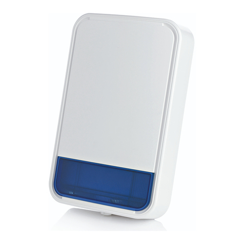
A. SR-740 PG2 can be
recognized outwardly by its
red screw cap.
Fig. 1a - External View
B. Wall
Fig. 1b – Mounting Position
Self-test feature
Upon pressing the self test switch, siren functional check is
performed - low level sounds and flash light indicate that the siren
is serviceable.
2 D-304921 SR-740 PG2 Installation Instructions
2
22
2.
. .
. INSTALLATION
INSTALLATIONINSTALLATION
INSTALLATION
1. Open plastic cover screw.
2. Using Philips screwdriver, remove screw and remove cover.
3. Optional step: Hang back unit with a screw on mounting
surface to make the next step (drilling marking) easier.
4. Mark for drilling.
5. Drill 5 holes.
6. Fasten with 5 screws.
7. Release catch (A) and open battery cover (B).
8. Connect the two connectors in their respective sockets.
9. Insert the battery and connect the battery connector.
A. Mounting surface.
B. For tamper.
C. Self-Test button.
D. Enroll button.
E. Primary battery.
F. Battery connector.
CAUTION! Risk of explosion if battery is replaced by an incorrect
type. Dispose of used battery according to manufacturer's
instructions.
Figure 2: Installation
3
33
3. ENROLLMENT
. ENROLLMENT. ENROLLMENT
. ENROLLMENT
Refer to the PowerMaster panel's Installer Guide and follow the procedure under the "02:ZONES/DEVICES" option of the Installer Menu.
A general description of the procedure is provided in the following flow chart.
Step 1 Step 2 Step 3 Step 4 Step 5
Enter the Installer menu
and select
“02:ZONES/DEVICES”
Select "ADD NEW DEVICE"
See Note 1
Enroll the device or enter the
device ID
Select the desired siren
number for the new siren
Configure Location,
Zone Type & Chime
Parameters





MODIFY DEVICES
SR1.SET CHIME
SR1.ZONE TYPE
SR1.LOCATION
ID No. 410-XXXX
SR1:Siren Outdoor
ENTR ID:XXX-XXXX
ENROLL NOW or
ADD NEW DEVICES
02:ZONES/DEVICES
D-304921 SR-740 PG2 Installation Instructions 3
Step 6 Step 7 Step 8 Notes:
1. If the siren is already enrolled, you can
configure the siren parameters and assign
partitions via the “Modify Devices” option –
see Step 2.
2. PARTITIONS will appear only if
PARTITIONING was previously enabled in a
panel that supports the Partitioning feature (for
further details, see "Partitioning" in the
PowerMaster Installer Guide).
3. When there is an alarm, the siren will sound
regardless of partition assignment.
Enter PARTITIONS.
See Note 2
Assign partitions to the
detector by pressing the
, and
buttons on the panel
Select the "DEV SETTINGS"
option and refer to the section
below to configure the siren
parameters.


means scroll and select
4
44
4.
. .
. CONFIGURING THE SIREN PARAMETERS
CONFIGURING THE SIREN PARAMETERSCONFIGURING THE SIREN PARAMETERS
CONFIGURING THE SIREN PARAMETERS
Enter the menu and follow the configuration instructions for the SR-740 PG2 outdoor siren as described in the following
table.
Option Configuration Instructions
Here you determine whether or not to activate the strobe alarm, and if activated, whether to activate the strobe until
the alarm system is disarmed, or, for the programmed period of time (see "Siren Configuration" section in the
control panel Installer Guide).
Optional settings: Timer limited (default), Disabled and Until Disarmed
Here you determine whether or not to activate the exit – entry beeps, and if enabled, whether to activate in HOME or
AWAY mode.
Optional settings: Disabled (default), Disabled & Home and Enabled.
Here you determine whether or not to enable the squawk, and if enabled, whether to activate the sounder only, or, the
sounder and strobe simultaneously.
Optional settings: Disabled (default), Sounder only, Strobe only and Sounder+strobe.
Here you determine the volume level of the sounder.
Optional settings: Volume HIGH(default), Volume LOW and Volume MID.
•
Here you determine whether or not the LED will be activated to indicate that the siren is operating.
Optional settings: Disabled (default) and Enabled.
•
Here you determine whether or not the siren alone will sound a tamper alarm when there is no communication
between the siren and the control panel.
Optional settings: Disabled (default) and Enabled.
5
55
5.
. .
. LOCAL DIAGNOSTICS TE
LOCAL DIAGNOSTICS TELOCAL DIAGNOSTICS TE
LOCAL DIAGNOSTICS TEST
STST
ST
Before testing, remove the plastic cover and then open the
battery cover (see Fig. 2).
A. Press the self-test button once and release it; the following
procedure should occur in turn:
The red LED will switch ON and then OFF, the green LED will
switch ON and then OFF, the strobe light will switch ON and
then OFF and the piezo siren will sound to indicate that the
siren is now fully operational.
B. After 2 seconds the LED blinks 3 times.
The following table indicates received signal strength
indication.
LED response Reception
Green LED blinks Strong
Orange LED blinks Good
Red LED blinks Poor
No blinks No communication
IMPORTANT! Reliable reception must be assured. Therefore,
"poor" signal strength is not acceptable. If you receive a "poor"
signal from the device, re-locate it and re-test until a "good" or
"strong" signal strength is received.
Note: For detailed Diagnostics Test instructions refer to the
control panel Installer Guide.
AUTO TAMPER ALRM
ACTIVITY LED
SOUNDER VOLUME
SQUAWK
EXIT-ENTRY Beeps
STROBE ALARM
DEVICE SETTINGS
SR1: DEV SETTINGS
SR1:P1P2 P3
SR1:PARTITIONS
4 D-304921 SR-740 PG2 Installation Instructions
6
66
6.
. .
. COMPLIANCE WITH STANDARDS
COMPLIANCE WITH STANDARDSCOMPLIANCE WITH STANDARDS
COMPLIANCE WITH STANDARDS
Compliance with Standards
Europe: EN50131-1 Grade 2 Class 4, EN 50131-4, EN 301489, EN 50130-4, EN 50130-5, EN 300 220, EN 60950-1,
EN 60950-22 Environmental IP55.
The SR-740 PG2 is compatible with the RTTE requirements - Directive 1999/5/EC of the European Parliament and of the Council of
9 March 1999 and EN50131-1 Grade 2 Class 4.
EN 50131-4, EN 50131-5-3, EN 50130-4, and EN 50130-5.
UK: This product is suitable for use in systems installed to conform to PD6662:2010 at Grade 2 and environmental class 4.
DD243 and BS8243
The Power G peripheral devices have two- way communication functionality, providing additional benefits as described in the
technical brochure. This functionality has not been tested to comply with the respective technical requirements and should
therefore be considered outside the scope of the product’s certification.
EN 50131-1 Security Grade According to EN 50131-1:2006 and A1:2009, this equipment can be applied in installed systems up to and including Security
Grade 2.
EN 50131-1 Environmental Class Class 4
WARNING! Changes or modifications to this unit not expressly approved by the party responsible for compliance could void the user’s authority to operate the equipment.
Le présent appareil est conforme aux CNR d'Industrie Canada applicables aux appareils radio RSS-210. L'exploitation est autorisée aux deux
conditions suivantes : (1) l'appareil ne doit pas produire de brouillage, et (2) l'utilisateur de l'appareil doit accepter tout brouillage radioélectrique
subi, même si le brouillage est susceptible d'en compromettre le fonctionnement.
Le dispositif doit être placé à une distance d'au moins 20 cm à partir de toutes les personnes au cours de son fonctionnement normal. Les
antennes utilisées pour ce produit ne doivent pas être situés ou exploités conjointement avec une autre antenne ou transmetteur.
W.E.E.E. Product Recycling Declaration
For information regarding the recycling of this product you must contact the company from which you orignially purchased it. If you are discarding this product and not
returning it for repair then you must ensure that it is returned as identified by your supplier. This product is not to be thrown away with everyday waste.
Directive 2002/96/EC Waste Electrical and Electronic Equipment.
7
77
7. SPECIFICATIONS
. SPECIFICATIONS. SPECIFICATIONS
. SPECIFICATIONS
Frequency Band (MHz): Europe: 433, 868
Modulation: GFSK
Antenna: Built-in antenna
Communication Protocol: PowerG
Current consumption:
Quiescent mode: 50µA
Alarm sound operated: 430mA
Siren Type:
At least 85 dBA at 10 ft (3 m)
Sound Pressure Level @ 1m, 1.4-3.2 kHz, sweep frequency 7 Hz.
Additional piezo is optional.
Power Supply: Type C
Battery Type: Four 3.6V/3.5A/H Lithium independent cells (EVE
ER18505M) assembled in two plastic wrappings and connected to the
cable adaptor (see Figure 2). Visonic assembly catalog no. 103-
304742.
Note: Use only the above battery.
Note: The strobe flashes 5 times and the red LED lights
continuously during first battery installation.
Battery Life Expectancy: 8 years (for typical use)
Low Battery Threshold: 2 V +300 mV negative slope OR 1.2 V
Strobe Light: Pulsed @ 1 sec.
Operating Temperature: -33°C to 70°C (-27.4°F to 158°F), RH
humidity 75%.
Dimensions (LxWxD): 295x186x63mm (11-5/8 x 7-5/16 x 2-1/2 in)
Weight (including battery): 970g (34 oz)
Color: White (with red, blue, amber or transparent lens)
WARRANTY
Visonic Limited (the “Manufacturer") warrants this product only (the "Product") to the original purchaser only (the
“Purchaser”) against defective workmanship and materials under normal use of the Product for a period of twelve
(12) months from the date of shipment by the Manufacturer.
This Warranty is absolutely conditional upon the Product having been properly installed, maintained and operated
under conditions of normal use in accordance with the Manufacturers recommended installation and operation
instructions. Products which have become defective for any other reason, according to the Manufacturers
discretion, such as improper installation, failure to follow recommended installation and operational instructions,
neglect, willful damage, misuse or vandalism, accidental damage, alteration or tampering, or repair by anyone
other than the manufacturer, are not covered by this Warranty.
The Manufacturer does not represent that this Product may not be compromised and/or circumvented or that the
Product will prevent any death and/or personal injury and/or damage to property resulting from burglary, robbery,
fire or otherwise, or that the Product will in all cases provide adequate warning or protection. The Product,
properly installed and maintained, only reduces the risk of such events without warning and it is not a guarantee
or insurance that such events will not occur.
THIS WARRANTY IS EXCLUSIVE AND EXPRESSLY IN LIEU OF ALL OTHER WARRANTIES, OBLIGATIONS
OR LIABILITIES, WHETHER WRITTEN, ORAL, EXPRESS OR IMPLIED, INCLUDING ANY WARRANTY OF
MERCHANTABILITY OR FITNESS FOR A PARTICULAR PURPOSE, OR OTHERWISE. IN NO CASE SHALL
THE MANUFACTURER BE LIABLE TO ANYONE FOR ANY CONSEQUENTIAL OR INCIDENTAL DAMAGES
FOR BREACH OF THIS WARRANTY OR ANY OTHER WARRANTIES WHATSOEVER, AS AFORESAID.
THE MANUFACTURER SHALL IN NO EVENT BE LIABLE FOR ANY SPECIAL, INDIRECT, INCIDENTAL,
CONSEQUENTIAL OR PUNITIVE DAMAGES OR FOR LOSS, DAMAGE, OR EXPENSE, INCLUDING LOSS
OF USE, PROFITS, REVENUE, OR GOODWILL, DIRECTLY OR INDIRECTLY ARISING FROM
PURCHASER’S USE OR INABILITY TO USE THE PRODUCT, OR FOR LOSS OR DESTRUCTION OF
OTHER PROPERTY OR FROM ANY OTHER CAUSE, EVEN IF MANUFACTURER HAS BEEN ADVISED OF
THE POSSIBILITY OF SUCH DAMAGE.
THE MANUFACTURER SHALL HAVE NO LIABILITY FOR ANY DEATH, PERSONAL AND/OR BODILY
INJURY AND/OR DAMAGE TO PROPERTY OR OTHER LOSS WHETHER DIRECT, INDIRECT, INCIDENTAL,
CONSEQUENTIAL OR OTHERWISE, BASED ON A CLAIM THAT THE PRODUCT FAILED TO FUNCTION.
However, if the Manufacturer is held liable, whether directly or indirectly, for any loss or damage arising under this
limited warranty, THE MANUFACTURER'S MAXIMUM LIABILITY (IF ANY) SHALL NOT IN ANY CASE
EXCEED THE PURCHASE PRICE OF THE PRODUCT, which shall be fixed as liquidated damages and not as a
penalty, and shall be the complete and exclusive remedy against the Manufacturer.
When accepting the delivery of the Product, the Purchaser agrees to the said conditions of sale and warranty and
he recognizes having been informed of.
Some jurisdictions do not allow the exclusion or limitation of incidental or consequential damages, so these
limitations may not apply under certain circumstances.
The Manufacturer shall be under no liability whatsoever arising out of the corruption and/or malfunctioning of any
telecommunication or electronic equipment or any programs.
The Manufacturers obligations under this Warranty are limited solely to repair and/or replace at the
Manufacturer’s discretion any Product or part thereof that may prove defective. Any repair and/or replacement
shall not extend the original Warranty period. The Manufacturer shall not be responsible for dismantling and/or
reinstallation costs. To exercise this Warranty the Product must be returned to the Manufacturer freight pre-paid
and insured. All freight and insurance costs are the responsibility of the Purchaser and are not included in this
Warranty.
This warranty shall not be modified, varied or extended, and the Manufacturer does not authorize any person to
act on its behalf in the modification, variation or extension of this warranty. This warranty shall apply to the
Product only. All products, accessories or attachments of others used in conjunction with the Product, including
batteries, shall be covered solely by their own warranty, if any. The Manufacturer shall not be liable for any
damage or loss whatsoever, whether directly, indirectly, incidentally, consequentially or otherwise, caused by the
malfunction of the Product due to products, accessories, or attachments of others, including batteries, used in
conjunction with the Products. This Warranty is exclusive to the original Purchaser and is not assignable.
This Warranty is in addition to and does not affect your legal rights. Any provision in this warranty which is
contrary to the Law in the state or country were the Product is supplied shall not apply.
Warning: The user must follow the Manufacturer’s installation and operational instructions including testing the
Product and its whole system at least once a week and to take all necessary precautions for his/her safety and
the protection of his/her property.
1/08
EMAIL: [email protected]
INTERNET: www.visonic.com

VISONIC LTD. 201
4
D
-
304921 SR
-
740 PG2 (REV.
2
,
10
/1
4
)

Other Visonic Security System manuals

Visonic POWERMAX - User manual

Visonic

Visonic POWERMAX - User manual

Visonic PowerMax10 User manual

Visonic

Visonic PowerMax10 User manual

Visonic PowerMaster-360R User manual

Visonic

Visonic PowerMaster-360R User manual

Visonic POWERMASTER-10 Assembly instructions

Visonic

Visonic POWERMASTER-10 Assembly instructions

Visonic POWERMAXEXPRESS - Assembly instructions

Visonic

Visonic POWERMAXEXPRESS - Assembly instructions

Visonic AXS-10 User manual

Visonic

Visonic AXS-10 User manual

Visonic POWERMASTER-10 User manual

Visonic

Visonic POWERMASTER-10 User manual

Visonic MCS-710 User manual

Visonic

Visonic MCS-710 User manual

Visonic IR-50 User manual

Visonic

Visonic IR-50 User manual

Visonic POWERMAXEXPRESS - User manual

Visonic

Visonic POWERMAXEXPRESS - User manual

Visonic POWERMAX - User manual

Visonic

Visonic POWERMAX - User manual

Visonic POWERMASTER-10 User manual

Visonic

Visonic POWERMASTER-10 User manual

Visonic MCS-730 User manual

Visonic

Visonic MCS-730 User manual

Visonic POWERMAX - Assembly instructions

Visonic

Visonic POWERMAX - Assembly instructions

Visonic POWERMAXCOMPLETE PANEL - User manual

Visonic

Visonic POWERMAXCOMPLETE PANEL - User manual

Visonic PowerMax Complete User manual

Visonic

Visonic PowerMax Complete User manual

Visonic MCS-730 User manual

Visonic

Visonic MCS-730 User manual

Visonic AXS-10 PRO User manual

Visonic

Visonic AXS-10 PRO User manual

Visonic rMaster-360 User manual

Visonic

Visonic rMaster-360 User manual

Visonic AMBER SELECT User manual

Visonic

Visonic AMBER SELECT User manual

Visonic POWERMAX PRO Assembly instructions

Visonic

Visonic POWERMAX PRO Assembly instructions

Visonic PowerMax Complete User manual

Visonic

Visonic PowerMax Complete User manual

Visonic POWERMAX PRO User manual

Visonic

Visonic POWERMAX PRO User manual

Visonic SR-720 PG2 User manual

Visonic

Visonic SR-720 PG2 User manual

Popular Security System manuals by other brands

ACTi B41 Manual guide

ACTi

ACTi B41 Manual guide

ITALIANA SENSORI 8156-ISS021 Installation, operation and maintenance manual

ITALIANA SENSORI

ITALIANA SENSORI 8156-ISS021 Installation, operation and maintenance manual

Kidde KN-COP-DP-10YL-AQ-WF user guide

Kidde

Kidde KN-COP-DP-10YL-AQ-WF user guide

Ansul AUTOPULSE Z-20 installation manual

Ansul

Ansul AUTOPULSE Z-20 installation manual

ADEMCO VIA-30PSE Programming guide

ADEMCO

ADEMCO VIA-30PSE Programming guide

Risco ProSYS Plus Quick installer's guide

Risco

Risco ProSYS Plus Quick installer's guide

PIEPS DSP manual

PIEPS

PIEPS DSP manual

Honeywell VISTA 15P - Ademco 6 Zone Control Panel Installation and operation guide

Honeywell

Honeywell VISTA 15P - Ademco 6 Zone Control Panel Installation and operation guide

fadini EAR 35 quick start guide

fadini

fadini EAR 35 quick start guide

Directed Electronics Vehicle Security System 3901V installation guide

Directed Electronics

Directed Electronics Vehicle Security System 3901V installation guide

FAAC AT-4 installation guide

FAAC

FAAC AT-4 installation guide

QOLSYS IQ TEMP Quick install guide

QOLSYS

QOLSYS IQ TEMP Quick install guide

Risco Agility 3 Installer manual

Risco

Risco Agility 3 Installer manual

Tynetec Advent XT2 installation manual

Tynetec

Tynetec Advent XT2 installation manual

Orion OLW-4651 user manual

Orion

Orion OLW-4651 user manual

ritm Contact GSM-2 quick start guide

ritm

ritm Contact GSM-2 quick start guide

Renkforce 1369187 operating instructions

Renkforce

Renkforce 1369187 operating instructions

Elkron HP602L installation manual

Elkron

Elkron HP602L installation manual

manuals.online logo
manuals.online logoBrands
  • About & Mission
  • Contact us
  • Privacy Policy
  • Terms and Conditions

Copyright 2025 Manuals.Online. All Rights Reserved.