1010
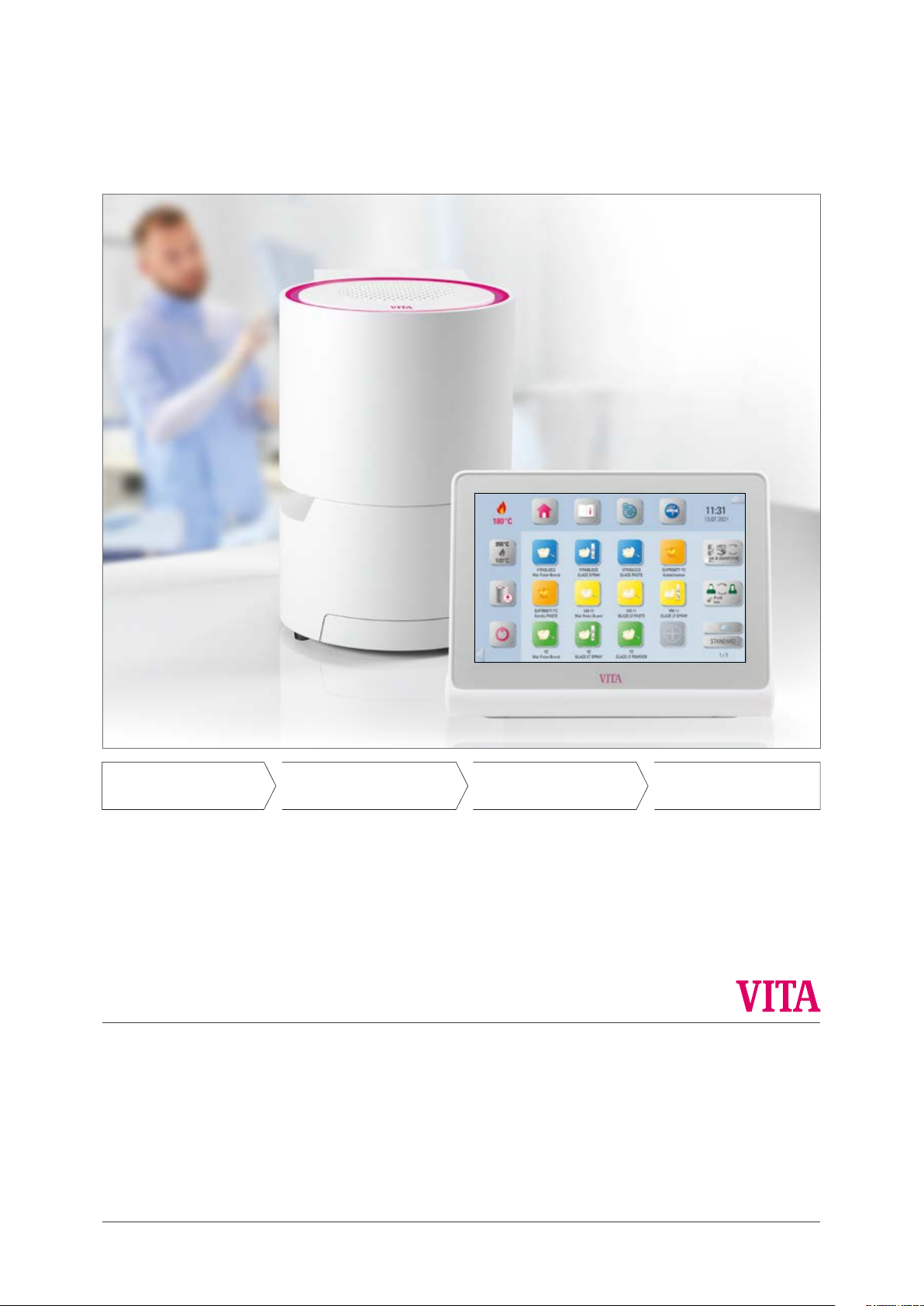
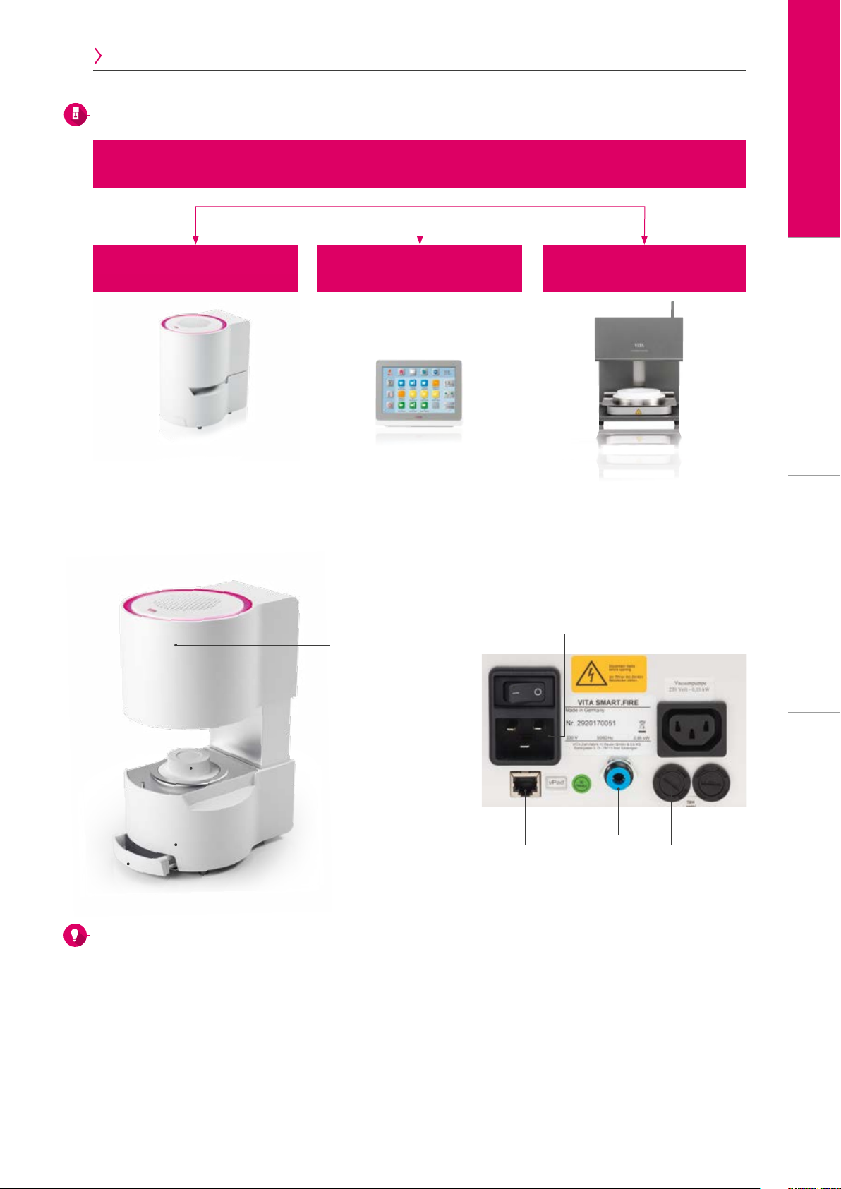
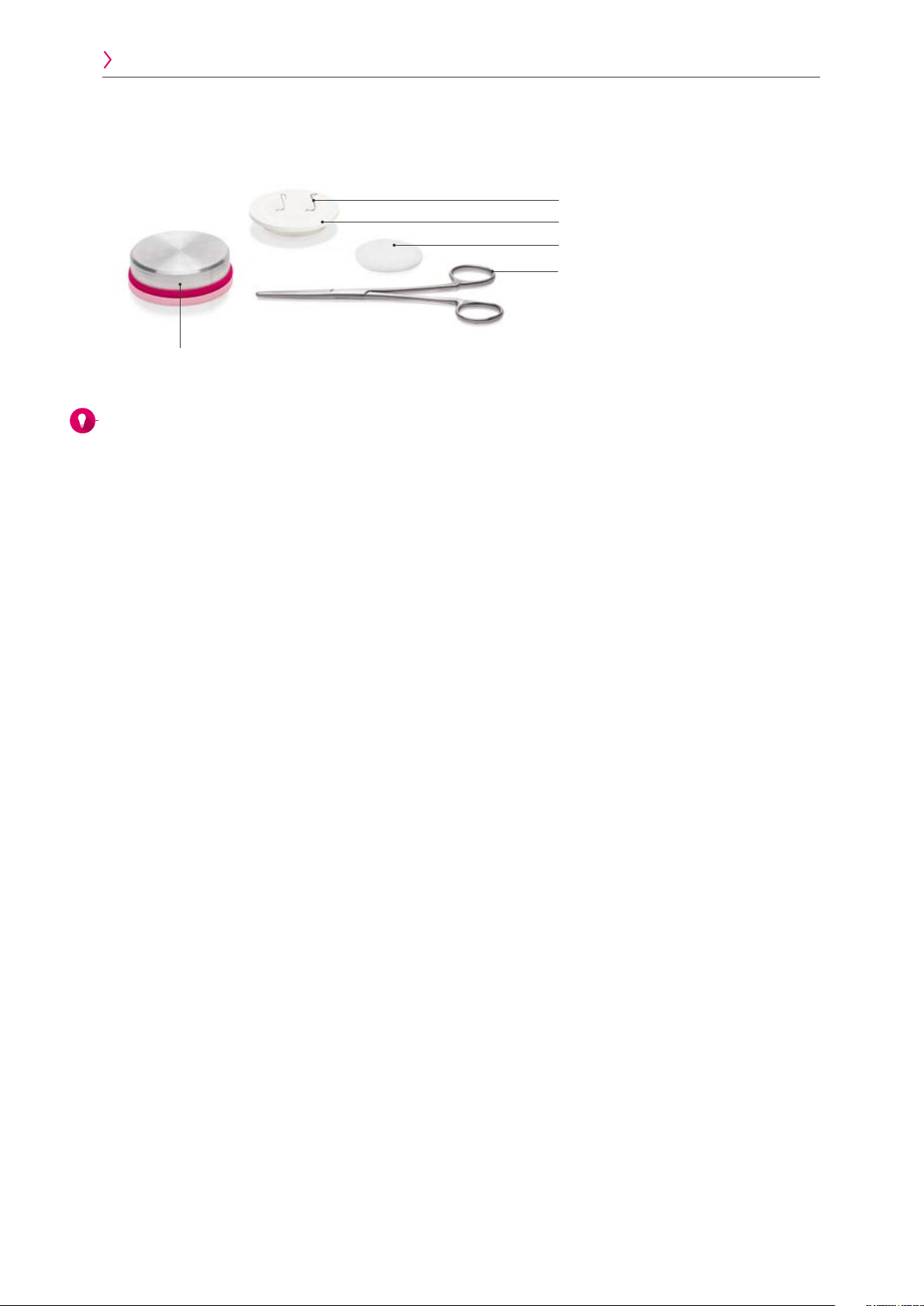
Product Scope of supply
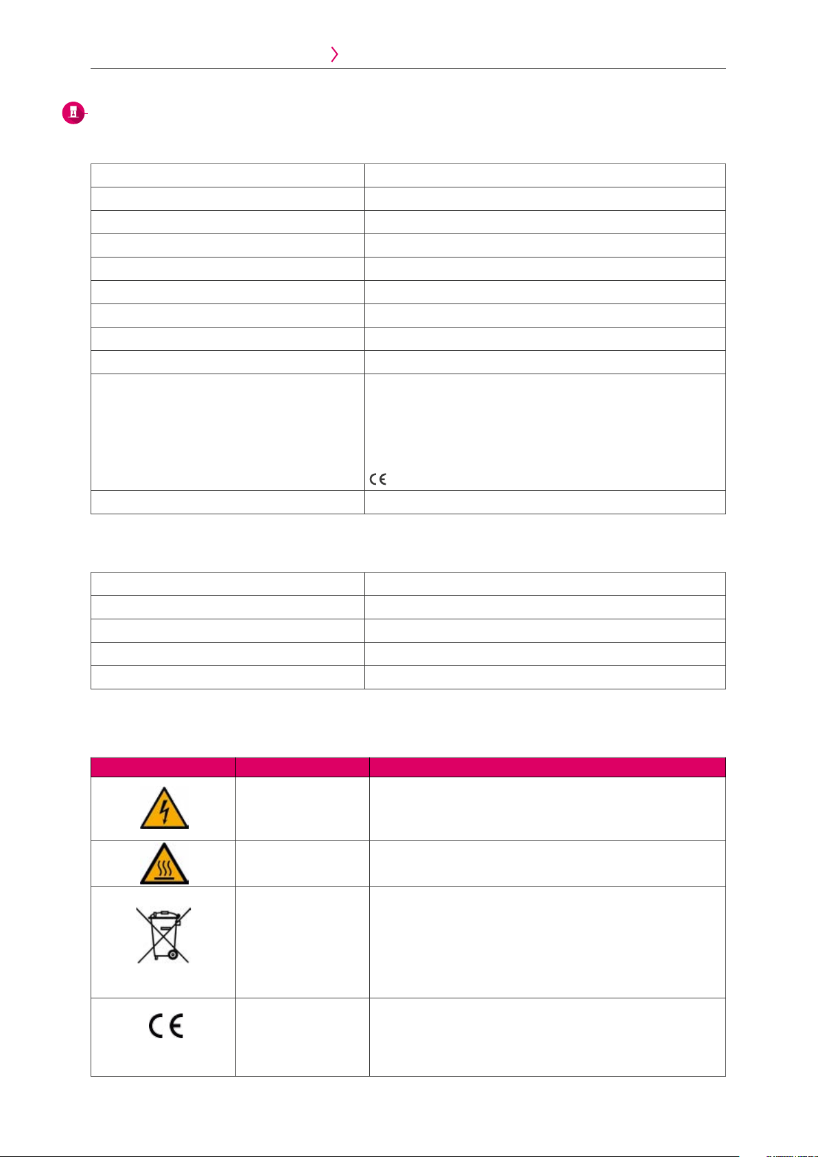
Hazardous voltage This pictogram warns the user about hazardous voltage. Before opening
the instrument, always disconnect it from the mains current by unplugging
the power plug.
Hot surface This pictogram warns the user about hot surfaces Burns are possible.
Separate disposal This unit and all accessories labeled with this symbol are subject to Directive
2002/96/EC (WEEE) and the applicable national regulations and may not be
disposed of as unsorted municipal waste in the European Union (EU).
Old units can be returned to VITA Zahnfabrik.
CE marking VITA SMART.FIRE complies with the applicable regulations of the European
Union (EU). The declaration of conformity can be requested from VITA
(Regulatory Affairs Department) at: www.vita-zahnfabrik.com
3. Scope of supply / system solutions 4. Technical data / information 5. Additional information
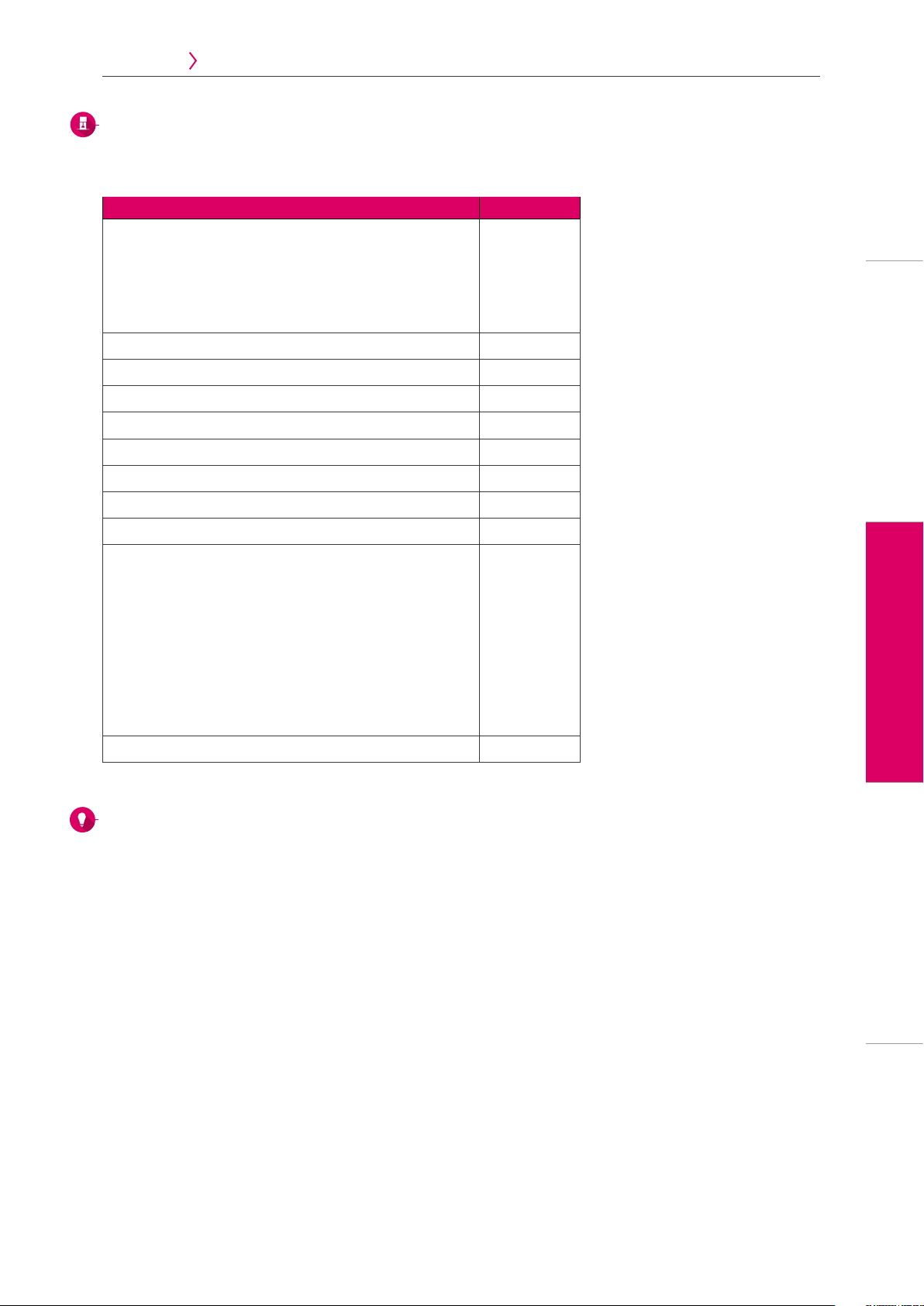
4. Technical data / information
4.1 Technical data for firing unit
4.2 Technical data for control unit
Dimensions (Ø / depth / height) 230 mm / 300 mm / 340 mm (closed)
Net weight 12 kg
Firing chamber internal dimensions (Ø / height) 80 mm / 43 mm
Firing chamber temperature Max. 1050°C
Electrical connection Specified on identification plate, tolerance ±10 %
Power consumption Max. 950 W (230 V), max. 1100 W (100 V, 110 V)
Temperature range for operation: 10°C to 35°C
Humidity for operation Max. 80% RH
Operating altitude Max. 3,800 m above sea level
Classifications EN 61010-10:2010
EN 61010-2-010:2014
UL 61010-1:2012
UL 61010-2-010:2015
CAN/CSA-C22.2 NO. 61010-2-010:2015
Application area Approved for indoor operation only
Dimensions (width / depth / height) 260 mm / 150 mm / 200 mm
Net weight 1.6 kg
Temperature for operation 10°C to 35°C
Humidity for operation Max. 80 % RH
Application area Approved for indoor operation only
4.3 Symbols