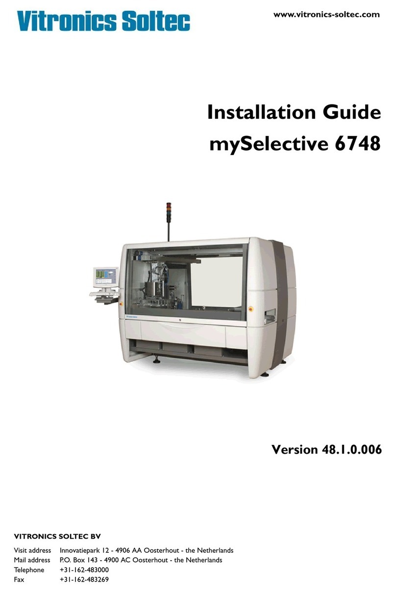
Vitronics Soltec MR620A User manual

Installation Guide myReflow.com
Version 38.1.0.003
VITRONICS SOLTEC BV
Visit adress Innovatiepark 12 - 4906 AA Oosterhout - the Netherlands
Mail adress P.O. Box 143 - 4900 AC Oosterhout - the Netherlands
Telephone +31-162-483000
Fax +31-162-483269
www.vitronics-soltec.com

ii
Rights
COPYRIGHT 2005 VITRONICS SOLTEC BV
All rights reserved. No part of this publication may be reproduced, stored in a retrieval system, or transmitted in any form or by any
means, electronic, mechanical, photocopying, recording or otherwise, without the prior written permission of Vitronics Soltec BV.
This publication remains the property of Vitronics Soltec BV and may not be passed, loaned or given to any third party.
Vitronics Soltec BV reserves the right to make changes in design and specifications without notice.
EUROPE
VITRONICS SOLTEC BV VITRONICS SOLTEC GmbH
Innovatiepark 12 An der Köhlerei 7
4906 AA Oosterhout 97828 Marktheidenfeld
the Netherlands Germany
Tel. +31-162-483000 Tel. +49-9391-98820
Fax +31-162-483269 Fax +49-9391-988228
AMERICAS
VITRONICS SOLTEC Inc.
2 Marin Way
Stratham, New Hamphire 03885
USA
Tel. +1-603-772-7778
Fax +1-603-772-7776
ASIA PACIFIC
VITRONICS SOLTEC PTE LTD. VITRONICS SOLTEC SHANGHAI
135 Joo Seng Road Room 902, Ocean Towers,
#02-01 PM Industrial Building No. 550 YanAn Road (E)
Singapore 368363 Shanghai, 200001, China
Tel. +65-484-3010 Tel. +86-21-6360-9936
Fax +65-484-1910 Fax +86-21-6360-9449
VITRONICS SOLTEC KOREA VITRONICS SOLTEC MALAYSIA
A-1001, Poonglim Iwant Bldg., 8-2-5 Sunny Point Complex
255-1 Seohyun Dong, Jalan Sultan Azlan Shah, Batu Uban,
Bundang Gu, Seongnam 463-862, Korea 11700 Penang, Malaysia
Tel. +82-31-783-7020 Tel. +60-4-658-4227
Fax +82-31-783-7021 Fax +60-4-655-4227
VITRONICS SOLTEC (SUZHOU) Co. Ltd
10 Huangpu Street
Lion Mountain Industrial Estate
Suzhou New District, China 215009
Tel. +86-512-6841-3378
Fax +86-512-6841-1711

Installation Guide myReflow.com iii
Preface
During the composition of this manual much attention is given to avoid errors
and mistakes. Also we aimed to give the contents a clear structure.
If during the use of this manual errors or incomplete descriptions are found, or
the reader considers that improvements are necessary to overcome any in-
accuracies, please inform us. We appreciate any comments which will help us to
improve this documentation.
For corrections or clarifications please contact:
1. By mail:
VITRONICS SOLTEC BV
HEAD OFFICE
TECHNICAL PUBLICATIONS
P.O. BOX 143
4900 AC OOSTERHOUT
THE NETHERLANDS
TEL NR. (31) - 162483000
FAX.NR. (31) - 162483285
OR
2. By e-mail:
hoosterhout@nl.vitronics-soltec.com

iv

Installation Guide myReflow.com v
Table of Contents
Preface iii
Table of Contents v
1 Installation 1-1
1.1 General . . . . . . . . . . . . . . . . . . . 1-1
1.2 Transport . . . . . . . . . . . . . . . . . . 1-1
1.2.1 Symbols used . . . . . . . . . . . . . . . 1-1
1.3 Unpacking . . . . . . . . . . . . . . . . . . 1-2
1.3.1 Packet in crate . . . . . . . . . . . . . . . 1-2
1.3.2 Packed on wooden pallet . . . . . . . . . . . 1-2
1.3.3 Lifting with forklift . . . . . . . . . . . . . 1-3
1.4 Connections . . . . . . . . . . . . . . . . . 1-4
1.4.1 General . . . . . . . . . . . . . . . . . 1-4
1.4.2 Electrical connection . . . . . . . . . . . . . 1-4
1.4.3 Nitrogen connection . . . . . . . . . . . . . 1-4
1.4.4 Exhaust system . . . . . . . . . . . . . . 1-4
1.4.5 Personal computer . . . . . . . . . . . . . 1-5
1.5 Opening cover for leveling . . . . . . . . . . . . . 1-6
1.6 Leveling . . . . . . . . . . . . . . . . . . . 1-7
1.7 Installation Sheet . . . . . . . . . . . . . . . . 1-8
1.8 Installation requirements . . . . . . . . . . . . . 1-10
Index vii

vi

ICON DESCRIPTION ICON DESCRIPTION
Only Qualified personnel is allowed to work on the
equipment.
Never eat, drink or smoke while working on the
machine.
Wash thoroughly before eating, drinking or smoking.
High voltages are present on various parts of the sys-
tem.
Before working on the electrical circuit, turn main
power off and block the mainswitch with a padlock.
Always wear heat resistant gloves and protective
clothing when working on the machine.
If possible allow the machine to cool down before
starting working on the machine.
When burned, immerse in cold water immediately.
When the burn is severe, consult a physician as soon
as possible.
Always wear heat resistant gloves and protective
clothing when working on the machine.
If possible allow the machine to cool down before
starting working on the machine
When burned, immerse in cold water immediately.
When the burn is severe, consult a physician as soon
as possible.
No smoking or open fire near the machine.
Be sure a fire-extinguisher is in the surroundings of
the machine.
No smoking or open fire near the machine.
Be sure a fire-extinguisher is in the surroundings of
the machine.
All moving parts of the system, including pulleys,
belts, chains, coolingfans, sprocketwheels, vacuum-
doors and cylinders presents a potential danger.
Be careful with covers and doors. Always pay atten-
tion to opening and closing.
The vapours in the board preparation module are
chemical.
Also the dust on the surface of the solderpot is dan-
gerous when inhaled.
Avoid inhaling this vapours / dust by using mouth
protection.
When working on the machine, always protect your
eyes with safety glasses.
Signal light RED
- E-stop Active Nitrogen
N2
Follow the safety precautions and procedures
described in the Material Safety Data Sheet of
the Nitrogen supplier.
Signal light ORANGE
- Steady = Overload (outfeed full), Machine will
block,
- Flashing slow = Alarm
- Flashing fast = Critical alarm. Machine will block
UPS
Uninterruptible
Power Source
When mainswitch is switched OFF, always switch
the UPS to OFF.
Signal light GREEN
- Steady = Machine Run,
- Flashing slow = Machine not at setpoint, machine
stop
If these rules are not observed it can cause personal injury and/or damage to the machine
SAFETY RULES
GENERAL INFORMATION

.

Technical Reference myReflow.com CHAPTER 1 1
Installation 1
1.1 GENERAL
Installing only by trained Vitronics Soltec / Agent personnel.
At the end of this chapter an installation sheet is located.
1.2 TRANSPORT
1.2.1 SYMBOLS USED
FIGURE 1.1 SYMBOLS ON PACKAGING
1. Position pallet/box for transport
2. Breakable
3. Keep dry
4. Lift here (labels are placed on
position where forklift should lift)
12 4
3
VERSION 2005 March

INSTALLATION
2CHAPTER 1
1.3 UNPACKING
The Vitronics Soltec myReflow is packed on a wooden pallet. When necessary, the machine is
packed in crates (e.g. when shipped).
If packed in crates the following procedure (paragraph 1.3.1 and 1.3.2) should be followed.
When the machine is packed on a wooden pallet follow instructions in paragraph 1.3.2.
1.3.1 PACKET IN CRATE
FIGURE 1.2 CRATE
Use the above figure order A,B,C to uncrate. Other order can result in damaging the machine or
personal injury.
1.3.2 PACKED ON WOODEN PALLET
FIGURE 1.3 PACKING REMOVAL
CB
AUncrating order:
1. Take off top cover A.
2. Remove side panels B.
3. Remove front and backcover C.
1. Remove packing material

1.3 - UNPACKING
Technical Reference myReflow.com CHAPTER 1 3
FIGURE 1.4 STRAPS REMOVAL
1.3.3 LIFTING WITH FORKLIFT
When the transporting straps are removed, the myReflow can be placed on the place the cus-
tomer has provided.
FIGURE 1.5 FORKLIFT UNDER MACHINE
To lift and transport the myReflow use the positions as shown in the installation sheet at the end
of this document.
2. Remove the coverdoors at the
strap-positions (total 4).
3. Remove straps
coverdoor
strap
* = DISTANCE BETWEEN FORKS minimum 1200mm
*

INSTALLATION
4CHAPTER 1
1.4 CONNECTIONS
1.4.1 GENERAL
See for connection specifications the “install sheet” at the end of this chapter.
1.4.2 ELECTRICAL CONNECTION
Only qualified electricians should work on the electrical circuits of the machine.
1. Connect the mains leads in accordance with the diagrams.
Check the Current rotation of the phases. The current rotation of the phases L1, L2, L3 must be
clockwise.
2. Block the mainswitch in the “OFF” position with a padlock to prevent dangerous situations.
1.4.3 NITROGEN CONNECTION
1. Connect the supply hose to the hose connector at the infeed side of the machine.
1.4.4 EXHAUST SYSTEM
One exhaust gauge of 165 mm (6.5”) is provided. This should be connected with the customer’s
exhaust system (not supplied by Vitronics Soltec).
• Inflammable and/or explosive gas might develop in the machine because of the evaporation of
the solvent in the flux.
• An exhaust system that functions well, will bring the gases below the explosion concentra-
tions.
• It is therefore necessary to have a sufficient exhaust in the machine.
• The exhaust system also has to be checked continuously on its well functioning.
• The machine is prepared to interfere in the E-stop circuit of the machine with a potential free
contact of the exhaust system. This contact has to be normally open, and therefore closed
when the exhaust functions well (fail safe).
NEVER USE THE MACHINE WITHOUT THE EXHAUST SYSTEM.

1.4 - CONNECTIONS
Technical Reference myReflow.com CHAPTER 1 5
1.4.5 PERSONAL COMPUTER
The complete Personal Computer is packed in boxes for transporting.
FIGURE 1.6 INSTALLING PC
1. Unpack all boxes.
2. Unpack PC arm.
3. Slide signal column in position.
4. Install keyboard holder.
5. Install keyboard and mouse.
6. Install the monitor on PC arm.
7. Connect all cables to the PC.
❷
❸❹
❺
❼
❻

INSTALLATION
6CHAPTER 1
1.5 OPENING COVER FOR LEVELING
Before the machine can be leveled the power on the machine must be on.
Switching on is only allowed by qualified personnel.
1. Switch on the mainpower and PC.
2. Select the myReflow icon on your desktop to start the PC program.
3. Select from the Status Menu Reset.
4. Enter your username and password.
5. Select the E-stop reset.
FIGURE 1.7 OPEN COVER AND SET CONVEYOR AND WIDE POSITION
6. Open with key switch the cover.
7. Set conveyor at widest position.
❻❼

1.6 - LEVELING
Technical Reference myReflow.com CHAPTER 1 7
1.6 LEVELING
After the machine is placed on its location and the cover is opened, the next steps should be fol-
lowed.
FIGURE 1.8 ADJUSTING LEVEL
FIGURE 1.9 LEVELING
1. Adjust the threaded feet of the machine until it stands perfectly in both X and Y direction.
A spirit level should be placed on the frame for checking the X direction. For the Y-
direction the spirit level should be placed on both conveyorbars.
2. When machine is leveled, tighten the nuts (A). See Figure 1.8)
After this procedure the machine is mechanically correct installed.
36 mm open
17 mm open
A
B
ended spanner
ended spanner
57-139mm
X- level
TOPVIEW
SIDEVIEW
Y- l e v e l spirit-level

INSTALLATION
8CHAPTER 1
1.7 INSTALLATION SHEET
SideView
SideView
FrontView
TopView
DISTANCE BETWEEN FORKS minimum 1200mm
centre of lifting point
Forks complete under myReflow
ABD
ABD
ABD
A
C
D
BC
365.8
1700
Exhaust ø 165
Main
Electrical
Supply
120
188
164
1660
2154
1296
1380
150
Nitrogen 98
109
SideView
1352
1551
520
*
* = PCB width
50-508
57- 139
775
Conveyortofloor
832-914
All dimensions in mm
POS
ABCD
10
12
14
16
574
929
1284
2840
2840
2840
2840
-
-
-
2840
3988
4698
6118
5408
10951639
MR620A, MR620N, MR710A,
A = Air
N = Nitrogen
MR710N, MR730A & MR820A
MR730N, MR820N, MR840A &
MR840N, MR930N, MR1040A &
MR1130A
MR1040N & MR1130N
10
12
14
16
MR930A

1.7 - INSTALLATION SHEET
Technical Reference myReflow.com CHAPTER 1 9
FIGURE 1.10 SLIDING OUT DIMENSIONS GRS AND COOLING UNIT
FRONTSIDE

INSTALLATION
10 CHAPTER 1
1.8 INSTALLATION REQUIREMENTS
DESCRIPTION UNITS
MR 620
MR 710
MR 730
MR 820
MR 840
MR 930
MR 1040
MR1130
Input Voltage V3 x 400 (Supply tolerance +10%, -10%)
Frequency Hz 50/60
Start-Up power kVA
52
52
54
54
55
56
56
Slow Start-Up power kVA
44
44
44
44
44
44
44
Power required at setpoint
(depending on configuration, load and
setpoints)
kVA
8
8
9
9
10
11
11
Weight machine Air (maximum) kg/lb
2300 /
5071
2300 /
5071
2300 /
5071
2300 /
5071
2500 /
5522
2500 /
5522
2700 /
5952
2700 /
5952
Weight machine Nitrogen (maximum) kg/lb
2300 /
5071
2300 /
5071
2500 /
5522
2500 /
5522
2700 /
5952
2700 /
5952
2900 /
6393
2900 /
6393
Carrying capacity per leveling feet kg/lb
Nitrogen requirements minimum
(only for nitrogen machine)
bar/PSI 4.8 / 70
Nitrogen supply, maximum rate m3/hr /
cfm
50 / 29.43
Nitrogen connection type ½” female NPT
Exhaust volume at single connection
Air Mode - No GRS
m3/hr /
cfm
450 / 265 at 300 Pa
Exhaust volume at single connection
Air Mode - GRS - Nitrogen
m3/hr /
cfm
200 / 118 at 100 Pa
Exhaust connection mm /
inch
165 / 6.50
Clearance for operate & maintenance
front,-, infeed,- and outfeedside
mm /
inch
120 /47.25
Clearance for operate & maintenance
backside
mm /
inch
150 / 59.05
This manual suits for next models
15
Table of contents
Other Vitronics Soltec Industrial Equipment manuals
Popular Industrial Equipment manuals by other brands
Ebmpapst
Ebmpapst D4E133-DL01-H9 operating instructions
woodmizer
woodmizer Incline Log Deck Safety, operation and maintenance manual
Con-form
Con-form Walkway Assembly & instruction manual

preVent
preVent BR12b instruction manual
StoneAge
StoneAge BJV-M Operation and maintenance manual
Delta
Delta ASRTU-EC16AP1TA Operation manual
System air
System air SAVE-P VTR 250/B installation instructions
Spraying Systems
Spraying Systems AutoJet VC10 owner's manual
woodmizer
woodmizer SlabMizer MB200 quick start guide
LaserMech
LaserMech FiberMINI 2.0 Operation manual
MYPV
MYPV ESW AC-THOR 9s Assembly instructions
Master cool
Master cool 91498 instruction manual

